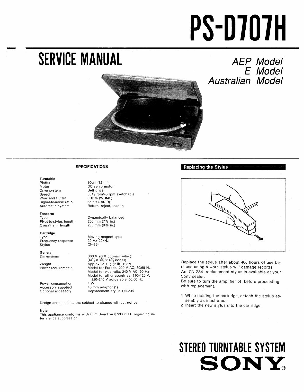
PS-D707H
ELECTRICAL
PARTS
LIST
NOTE:
¢
Due
to
standardization,
replacements
in
the
parts
list
may
be
different
from
the
parts
specified
in
the
diagrams
or
the
components
used
on
the
set.
*
-XX,
-X
mean
standardized
parts,
so
they
may
have
some
difference
from
the
original
one.
¢
RESISTORS
All
resistors
are
in
ohms
«
Items
marked
“*”
are
not
stocked
since
they
are
seldom
required
for
routine
service.
Some
delay
should
be
anticipated
when
ordering
these
items.
¢
SEMICONDUCTORS
In
each
case,
u:
u
,
for
example:
uA...
WA...,
UPA...
“ZPA...,
uUPB...:
WPB...,
UPC...:
uw
PC...,
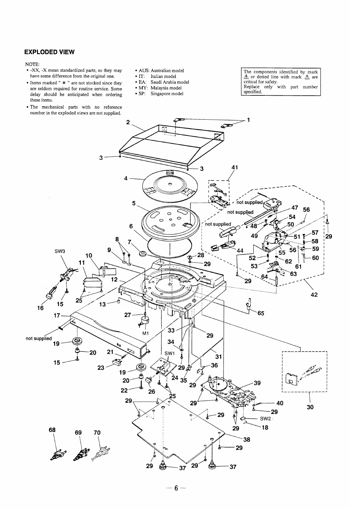
The
components
identified
by
mark
A\
or
dotted
line
with
mark
A\
are
critical
for
safety.
Replace
only
with
part
number
specified.
e
AUS:
Australian
model
¢
IT:
Italian
model
METAL:
Metal-film
resistor
ORD
ee
nO
e
EA:
Saudi
Arabia
model
METAL
OXIDE:
Metal
Oxide-film
resistor
.
end
ee
*
MY:
Malaysia
model
F
:
nonflammable
urs
SP:
Sj
»
COILS
SP:
Singapore
model
uH:
wH
Ref.No.
Part
No.
Description
Remark
|
Ref.No.
Part
No.
Description
Remark
x
1-649-544-11
POWER
BOARD
MISCELLANEOUS
EXKKKKARK
KE
HAKAKKKKKEREE
<
CAPACITOR
>
A\68
1-575-651-11
CORD,
POWER
(AEP,
IT,
EA,
MY)
A\69
1-590-074-11
CORD,
POWER
(E,
SP,
Tourist)
C901
1-124-360-00
ELECT
—
1000uF
10V
A\70
1-690-608-11
CORD,
POWER
(AUS)
SZ
1-572-746-21
SWITCH
MICRO
<
DIODE
>
S¥3
1-572-744-21
SWITCH
PUSH
D901
9-719-200-02
DIODE
10E-2
KRAKRKRKA
ERE
RARER
EKA ERA
RAKE
REE
K
RRR
R
ERR
R
AER
AREERKR
AREER
RAE
REE
D902.
«=:
9-719-200-02
DIODE
10E-2
D903
=
9-719-200-02
DIODE
10E-2
ACCESSORIES
&
PACKING
MATERIALS
D904.
+
9-719-200-02
DIODE
10E-2
EKEKAK
ERA
RAKRAK
EKER
KARE
AER
EEE
<
TRANSFORMER
>
ATI
1-423-815-11
TRANSFORMER,
POWER
(AEP,
IT)
ATl
1-423-815-21
TRANSFORMER,
POWER
(E,
EA,
MY,
SP,
AUS,
Tourist)
3-757-234-11
MANUAL,
INSTRUCTION
(ENGLISH,
FRENCH,
SPANISH,
PORTUGUESE)
(AEP)
3-757-234-41
MANUAL,
INSTRUCTION
©
(GERMAN,
DUTCH,
SWEDISH,
ITALIAN)
(AEP,
IT)
3-757-234-51
MANUAL,
INSTRUCTION
(AUS,
E)
¥
4~960-026-01
INDIVIDUAL
CARTON
eTttttititttietitetitsttitetitietetsssets
ist
ists
ste
se
rss
ser
sf
*
1-649-543-11
SPEED
SW
BOARD
FOO
AEE
<
RESISTOR
>
R101.
=1-247-818-11
CARBON
300
R102
1-249+410-11
CARBON
270
<
VARIABLE
RESISTOR
>
VR1
1-230-625-11
VARIABLE
RESISTOR
300
VR2
=
1-230-625-11
VARIABLE
RESISTOR
300
<
SWITCH
>
SW1.
1-572-744-21
SWITCH
PUSH
(SPEED)
petttttetetitcttitetitetis
cits
teste
resets
efit
te
tele
L
ees
ese
Lees
English
:
93H09015-1(2)
n
So
y
Corporation
Printed
in
Japan
9-957-932-12
Audio
Group
©
1993.5
(Including
9-957-932-81)
—
§—
Published
by
Audio
Sector
Quality
Assurance
Dept.