Read Only Disc.
(1)
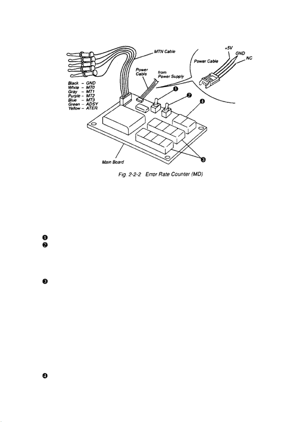
Configuration (Refer to Fig. 2-2-2)
Main Board
MTN Cable
Power Cable
(2) Error Rate Counter (MD) Function
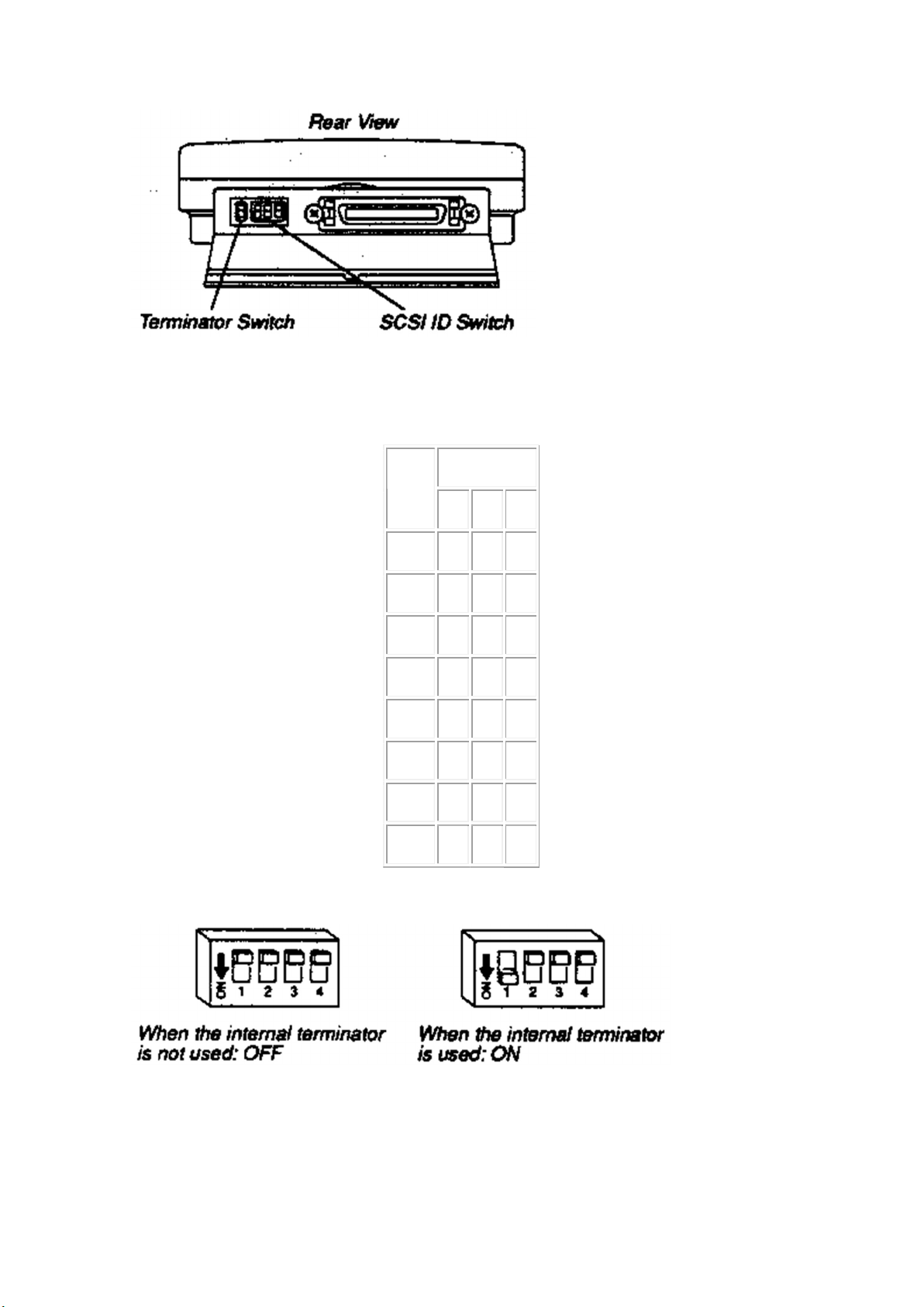
Switches
SW1 ... This switch is to supply DC5V voltage to this board.
SW2 ... When it is set to 10sec side, this will show the count number of C1, C2 and AT errors
appeared in 73500 frames (ten times as large as 7350) every 10 seconds. They are 10 times as
large as the usual ones (no. of C1, C2, AT errors in 7350 frames). Divide the total numbers by
10, and you can get the average numbers.
Indicators
C1/C2 Error (LED1 to 8) ... These indicate numbers of two types of data errors; Random error
and Burst error. The random error is an error of 1-2byte long which appears all over the disc
and the Burst error is a long error which locally appears in the disc.
To correct MD Data errors, CIRC (CD's error correction system) is used. The CIRC uses two
layered correction codes, C1 and C2. C1 for correcting Random Errors and C2 for correcting
Burst Errors.
The C1 count of this error rate counter indicates number of frames where any C1 corrections
were made. The C2 count indicates number of frames where an error(s) could not be corrected
even after C1 and C2 corrections were applied. Usually maximum 220 count of C1 error is
allowed, but C2 error must be 0 to retrieve correct data. In case of reading Rewritable Adj.
Disc, C2 error normally occurred at linking points between clusters, because recorded data is
discontinued. A continuously recorded cluster area is necessary to measure true C2 error rate.
Follow instructions in each section for the correct procedure.
ATER (LED9 and 10)... The Rewritable Adj. Disc has address (ADIP signals) which show the