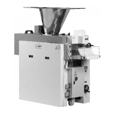
Sottoriva LYRA User manual

INSTRUCTIONS MANUAL
Automatic dividing and rounding centre
mod. LYRA
Version : ENGLISH - Arc. 91
Code : 3529.0169.01
Revision : n° 0 del 31/10/2007
Costruzioni Meccaniche SOTTORIVA S.p.A.
Via Vittorio Veneto, 63 - 36035 MARANO VICENTINO (VI) ITALIA
Tel. (+39) 0445.595.111 - Fax (+39) 0445.595.155
Internet: http://www.sottoriva.com - E-mail: sottoriva@sottoriva.com
at two rows


LYRA - Code: 3529.0169.01 Rev. 0
dated 31/10/2007
Arc. 91-ig PT 1007
EF 1007
MC 1007
Technical Assistance Service
Tel. (+39) 0445.595.111 1
Table of contents
1. Introduction.........................................................................................................3
1.1 Foreword........................................................................................................3
1.2 Warranty: terms and conditions......................................................................3
1.3 User instructions and precautions..................................................................5
2. Descriptive manual.............................................................................................9
2.1 Foreword........................................................................................................9
2.2 Working dimensions and other characteristics...............................................13
2.3 Machine plate.................................................................................................13
3. Operation and installation manual....................................................................15
3.1 Foreword........................................................................................................15
3.2 Getting the workplace ready...........................................................................15
3.3 Hoisting and transportation.............................................................................15
3.4 Assembly and installation...............................................................................17
3.4.1 Installation precautions ...........................................................................17
3.4.2 Instructions for the electrician .................................................................17
3.5 Start-up...........................................................................................................17
3.6 Operation........................................................................................................23
3.6.1 Electronic version....................................................................................23
3.6.2 Mechanical version .................................................................................25
3.6.3 Using and changing the rounding box.....................................................26
3.6.4 Using the dividing pistons .......................................................................27
4. Maintenance manual ..........................................................................................33
4.1 Foreword........................................................................................................33
4.2 Daily maintenance..........................................................................................33
4.3 Monthly maintenance.....................................................................................33
4.3.1 Tensioning method..................................................................................34
4.4 Quarterly maintenance...................................................................................34
4.5 Cleaning the machine.....................................................................................35
4.5.1 Cleaning the dividing chamber................................................................35
4.5.2 Cleaning the star cylinders......................................................................36
4.5.3 Cleaning the flouring unit ........................................................................36
4.5.4 Cleaning the dough hopper.....................................................................36
4.5.5 Cleaning the piece detaching cylinder and cylinder scraper...................37
4.5.6 Cleaning the dividing cylinders................................................................37
4.5.7 Cleaning the rounding box......................................................................38
4.5.8 Cleaning the separator conveyors (or outlet conveyor) and
the rounding conveyor..........................................................................38

Rev. 0
dated 31/10/2007 LYRA - Code: 3529.0169.01
2Technical Assistance Service
Tel. (+39) 0445.595.111
PT 1007
EF 1007
MC 1007 Arc. 91-ig
4.6 Replacing parts subject to wear .....................................................................40
4.6.1 Changing the piece depositing belts.......................................................40
4.6.2 Changing the rounding conveyor ............................................................41
4.6.3 Changing the rounding belts...................................................................41
4.6.4 Changing the main motor reducer...........................................................42
4.6.5 Changing the rounding motor..................................................................43
4.6.6 Changing the weight adjustment chain...................................................47
4.6.7 Checking the machine phasing (main piston - rotor)...............................48
4.6.8 Checking and adjusting the rounding unit and the blade conveyor.........48
4.6.9 Belt synchronism adjustment..................................................................51
4.7 Troubleshooting guide....................................................................................51
4.8 Electrical diagrams section.............................................................................52
4.8.1 Power circuit diagrams............................................................................52
4.8.1.1 Version with 230 V 50 Hz.................................................................52
4.8.1.2 Version with 400 V 50 Hz.................................................................52
4.8.2 Control circuit diagrams ..........................................................................52
4.8.3 Electrical maintenance............................................................................53
5. Safety and food hygiene manual.......................................................................55
5.1 General remarks.............................................................................................55
5.2 Dangers form mechanical parts and residual risks.........................................55
5.2.1 Danger area 1 (top area) ........................................................................55
5.2.2 Danger area 2 (rear area) .....................................................................55
5.2.3 Danger area 3 (left side) .......................................................................55
5.2.4 Danger area 4 (right side).......................................................................56
5.2.5 Danger area 5 (front)...............................................................................56
5.3 Electrical dangers...........................................................................................56
5.4 Safety warning signs ......................................................................................57
5.5 Noise..............................................................................................................58
5.6 Food hygiene requirements............................................................................58
5.7 Putting out of service......................................................................................59
5.8 Machine demolition - disposal........................................................................59
5.9 Final notes......................................................................................................59

LYRA - Code: 3529.0169.01 Rev. 0
dated 31/10/2007
Arc. 91-I PT 1007
EF 1007
MC 1007
Technical Assistance Service
Tel. (+39) 0445.595.111 3
1. Introduction
1.1 Foreword
1.2 Warranty: terms and conditions
The machine is covered by warranty for a period of twelve (12) months from
the date of delivery, the warranty being limited to parts with manufacturing
defects and excluding the motors and electrical system.
Furthermore, any parts damaged during transport or as a result of poor or
incorrect installation or maintenance, or because of negligence or improper
use are not covered by the terms of the warranty.
The warranty is valid for the original purchaser only and does not, under any
circumstances, include replacement of the machine.
The warranty is no longer valid if the machine is tampered with or subject to
alterations or repairs by personnel not authorised by SOTTORIVA S.p.A.
The manufacturer is not liable for any injury to persons or animals or
damage to objects caused, either directly or indirectly, by machine
breakdowns or as a result of not being able to use the machine.
Defective parts are normally repaired or replaced on the customer's
premises, with the travel, board and lodging expenses for the personnel
sent to effect the repairs or replacements being charged to the customer.
Transit time and hours worked bypersonnel are also charged to the customer;
the hourly rate will be calculated in accordance with the A.n.i.m.a. tables.
(National Associations of Mechanical Engineering and Affiliated Industries).
If, according to the unquestionable judgement of the technicians, the work
cannot be performed on the customer's premises, then the customer must
have the machine delivered free of carriage to C.M. SOTTORIVA S.p.A.
After the repairs have been effected free of charge, the customer must then
have the machine delivered back to their works, carriage paid.
If any repair work is performed after the expiry of the aforementioned
warranty period, the customer will be charged for labour (in accordance with
the ANIMA table), travel-board and lodging expenses, the cost of the
replaced parts and any transport costs for the replaced parts.
The rates will be calculated in accordance with the A.n.i.m.a. table in the
possession of the engineering staff.
Caution!
Read the information in this manual thoroughly before starting work
with the machine and carefully follow all instructions.
CONSERVE this manual and all its enclosures in an accessible place
for all operators and routine maintenance staff; the manual must be
kept in a dry place and, if possible, in a bag to protect it from external
agents such as dust, moisture, light, etc.

Rev. 0
dated 31/10/2007 LYRA - Code: 3529.0169.01
4Technical Assistance Service
Tel. (+39) 0445.595.111
PT 1007
EF 1007
MC 1007 Arc. 91-I
As a necessary condition for entitlement to warranty cover, the warranty
certificate (see facsimile below) must be completed and sent off within
15 days of the delivery date.
Moreover, if the applicant is unable to produce the copy of the certificate
kept by the customer, the warranty may be considered as annulled.

LYRA - Code: 3529.0169.01 Rev. 0
dated 31/10/2007
Arc. 91-I PT 1007
EF 1007
MC 1007
Technical Assistance Service
Tel. (+39) 0445.595.111 5
1.3 User instructions and precautions
The manufacturer declines all responsibility for any injury to persons or
animals or damage to objects resulting from the failure to observe any of the
previous or following information and instructions on the use or maintenance
of the machine:
zDO NOT USE the equipment for any purposes and/or loads different to
those stated by the manufacturer;
zEVERY DAY, CHECK the safety devices, oil level and general state of the
equipment;
zCLEAN THE EQUIPMENT thoroughly every day;
zTAKE ALL NECESSARY PRECAUTIONS and safetymeasureswhenloa-
ding, adjusting, changing parts or carrying out repair or maintenance work
on the machine, to make sure that the machine or any parts of it are not
accidentally started up by other persons;
zDO NOT TAMPER with guards and safety devices on the machine;
zDO NOT REMOVE the guards and safety devices on the machine unless
strictly necessary. Always take steps to reduce the related risks to a mini-
mum, as described fully and frequently in this manual;
zREPLACEalltheguardsandsafetydevicesassoonasthereasonfortheir
temporary removal no longer exists;
zOBSERVE THE FOLLOWING REGULATIONS regarding workplace
safety and procedures:
- regulations on safety notices and warnings as stated in DD.PP.RR. 27/4/55,
n° 547 and n° 524 of date 8/6/82 and D. Lgs. 493/96 for Italy, or equivalent
regulations in country of use of machine;
- European directives concerning workplace safety as stated in 89/391/EEC,
89/654/EEC, 89/655/EEC, 89/656/EEC, 90/269/EEC, 90/270/EEC,
90/394/EEC, 90/679/EEC, 95/63/EEC;
- European directives concerning individual protection measures as stated in
89/656/EEC and 89/686/EEC;
- European directives on the environment,with special regard to 91/156/EEC
concerning waste disposal, 91/689/EEC on the disposal of harmful waste
and 75/439/EEC on the disposal of used oils.
zINFORM ALL PERSONNEL of the specific hazards present in the work-
place.

Rev. 0
dated 31/10/2007 LYRA - Code: 3529.0169.01
6Technical Assistance Service
Tel. (+39) 0445.595.111
PT 1007
EF 1007
MC 1007 Arc. 91-I
Electronic version
Photo 1
Mechanical version
Photo 2
1
2
3
6
4
5
7
8
31
2
6
4
5
7
8

LYRA - Code: 3529.0169.01 Rev. 0
dated 31/10/2007
Arc. 91-I PT 1007
EF 1007
MC 1007
Technical Assistance Service
Tel. (+39) 0445.595.111 7
Fig. 1
Fig. 2
12345 6 7 8
Electronic version control panel
12345 6 78
Mechanical version control panel

Rev. 0
dated 31/10/2007 LYRA - Code: 3529.0169.01
8Technical Assistance Service
Tel. (+39) 0445.595.111
PT 1007
EF 1007
MC 1007 Arc. 91-I
Fig. 3
1
6
4
3
7
8
5
2
9
10

LYRA - Code: 3529.0169.01 Rev. 0
dated 31/10/2007
Arc. 91-II PT 1007
EF 1007
MC 1007
Technical Assistance Service
Tel. (+39) 0445.595.111 9
2. Descriptive manual
2.1 Foreword
The machine shown in Photo 1 on page 6 (electronic version) and/or
Photo 2 on page 6 (mechanical version) object of this manual is destined to
be used in industry and by bakeries (bakers and confectioners) to produce
rounded dough shapes for specific bakery and/or confectionery products
containing wheat flour and water as basic ingredients.
Use of the machine for any other purpose is to be considered dangerous for
the mechanical seal and therefore for the operator.
The manufacturer will under no circumstances be considered liable for
incorrect and/or improper use of the machine, unless it has been specifically
authorised.
The standard version of the machine comprises:
zA hopper ref. 7 Photo 1 and Photo 2 with a capacity of approximately 14
kg of dough.
zA first device to divide the dough into portions, using a star dosing system.
Arectangularsectionpistonref. 1 Fig. 3 onpage8compressesasufficient
amount of dough from the star dividing device, and then drops it into the
next dividing device.
The main piston compresses the dough using a lever system; a specially
designed channel system ensures that the dough is lightly treated before
entering the two weighing chambers.
zA rotating element ref. 5 Fig. 3 with a series of 2 chambers, into which is
pressed the dough from the first dividing system described above which,
rotating alternately by a set amount, separates it by cutting the dough
against the sliding surface. A series of small pistons ref. 2 Fig. 3 sliding
inside the chambers and with a stroke limited by two cams ref. 3 Fig. 3, as
well as ensuring that the required weight of dough enters the chambers,
also ensures that the dough collected by the cylinders and cut by the rota-
ting movement is expelled.
zA rounding system comprising a rounding chamber ref. 1 Fig. 9 on page
19 moves with a circular motion with the pieces of dough inside it, causing
them to rotate and mould themselves into a ball.
The pieces of dough to be rounded are arranged on a conveyor belt ref. 4
Fig. 3 which positions them under the mobile rounding box which, by low-
ering itself into the chambers it contains, collects the balls of dough which,
pressed onto the conveyor belt, start their circular rounding movement.
The pieces of dough, held within the chambers formed in the rounding box
by two opposite niches formed on the conveyor belt, thus take on a
rounded shape during rotation.
zThe rounding belt conveys the balls to the output, where they are picked
up by another conveyor belt ref. 1 Fig. 10 on page 19 or by two smaller
conveyor belts ref. 1 Fig. 11 on page 20.

Rev. 0
dated 31/10/2007 LYRA - Code: 3529.0169.01
10 Technical Assistance Service
Tel. (+39) 0445.595.111
PT 1007
EF 1007
MC 1007 Arc. 91-II
zA blade conveyor unit ref. 9 Fig. 3 on page 8 to collect the balls after divid-
ing and deposit them on the smaller conveyor belts.
The balls come out on the outlet conveyor ref. 1 Fig. 10 on page 19 at a
distance of approximately 110 mm from each other, while in the version
with two smaller conveyors this distance may be varied to between approx-
imately 110 and 200 mm.
zA pressing cylinder (optional) ref. 2 Fig. 9 on page 19 located on the outlet
conveyor, which can be adjusted according to the weight of the balls, to
flatten the balls as required and allow them to be fed out in a constant and
continuous manner.
zA stainless steel support surface ref. 3 Fig. 9.
zA flouring device (optional) ref. 1 Photo 10 on page 32 ensures that the
dough is well floured, keeping the residual humidity down, after dividing
with the rotation device ref. 1 Photo 5 on page 29.
The amount of flour dispensed is adjustable by means ofa perforatedinter-
nal wall, controlled by a sliding rod ref. 2 Photo 10 located at the front of
the flouring unit.
zAt the rear of the machine there is a manually operated main switch ref. 1
Fig. 6 on page 12.
The panel used to control and adjust the machine (electronic version) com-
prises:
zA “Touch Screen” control panel ref. 1 Photo 1 on page 6 with 50 storable
programs and PLC management.
The following variables can be stored in the programs:
- weight of the product;
- rounding box rotation speed;
- machine production speed (2.000/4.000 pcs/h);
- type of rounding box;
- piston size (complete external piston or internal piston).
The control panel also includes a series of buttons for the following func-
tions:
a) emergency stop ref. 1 Fig. 1 (red mushroom head button on yellow
ground);
b) lamp ref. 2 Fig. 1 (white light) indicating that the power supply is on;
c) selector ref. 3 Fig. 1 for single machine production or for insertion in a
system (if foreseen);
d) deviator ref. 4 Fig. 1 to turn the fan on or off (FAN);
e) selector ref. 5 Fig. 1 to stop the machine so as to clean the pistons
(CLEAN) or to change the rounding box (WORK);
f) normal stop and start ref. 6 Fig. 1;
g) Touch Screen control panel ref. 7 Fig. 1;
h) trimmer ref. 8 Fig. 1 toset and adjust the production speed(from 2.000 to
4.000 pcs/h).
The areas normally occupied by the operator are:
- the area in front of the control and adjustment panel;
- the area in front of the outlet conveyor, for manual pick-up and movement
of the product coming out of the machine.

LYRA - Code: 3529.0169.01 Rev. 0
dated 31/10/2007
Arc. 91-II PT 1007
EF 1007
MC 1007
Technical Assistance Service
Tel. (+39) 0445.595.111 11
If the machine is associated with others downstream, the last area
mentioned will obviously not be occupied by the operator.
On the control panel ref. 1 Fig. 2 on page 7 for control and adjustment of the
machine (mechanical version) there are a series of buttons with the
following functions:
a) emergency stop ref. 1 Fig. 2 (red mushroom head button on yellow
ground);
b) lamp ref. 2 Fig. 2 (white light) indicating that the power supply is on;
c) selector ref. 3 Fig. 2 for single machine production or for insertion in a
system (if foreseen);
d) deviator ref. 4 Fig. 2 to turn the fan on or off (FAN);
e) selector ref. 5 Fig. 2 to stop the machine so as to clean the pistons
(CLEAN) or to change the rounding box (WORK);
f) normal stop and start ref. 6 Fig. 2;
g) selector ref. 7 Fig. 2 to select production speed 1 or 2 (2060 pcs/h at
speed 1; 3200 pcs/h at speed 2);
h) selector ref. 8 Fig. 2 to turn the rounding function on and off.
To adjust the weight there is a flywheel ref. 2 Fig. 2, which if turned
anticlockwise results in an increase in the weight, and if turned clockwise
results in a decrease in the weight.
Fig. 4

Rev. 0
dated 31/10/2007 LYRA - Code: 3529.0169.01
12 Technical Assistance Service
Tel. (+39) 0445.595.111
PT 1007
EF 1007
MC 1007 Arc. 91-II
Fig. 5
Fig. 6
C.M. SOTTORIVA S.p.A.
Via Vittorio Veneto, 63
36035 MARANO VICENTINO
(Vicenza) - ITALY
Tel./Phone (+39) 0445.595.111
Fax (+39) 0445.595.155
P.I. 00768890246
E-mail:sottoriva@sottoriva.com
Internet:http://www.sottoriva.com
Mod.
n°
VXXX Hz XX
kW XX
LYRA
AXX 3 AC + (N) + T
Mass kg XXXX
200_
1
3
2

LYRA - Code: 3529.0169.01 Rev. 0
dated 31/10/2007
Arc. 91-II PT 1007
EF 1007
MC 1007
Technical Assistance Service
Tel. (+39) 0445.595.111 13
2.2 Working dimensions and other characteristics
The maximum rated production level for the machine is 2,000 pieces/hour
for each row used; the maximum number of dough balls produced may vary
approximately within the values given in Table 1, according to the size of the
dividing pistons ref. 2 Fig. 3 on page 8.
Fig. 4 on page 11 shows the working dimensions of the machine.
Table 1 and Table 2 give come technical information and a Table of the rated
powers of motors installed in the various models of machine.
The mass of the standard version of the machine is approximately 560 kg,
and the total mass with packaging is approximately 650 kg.
Table 1
Table 2
Table 3
2.3 Machine plate
In Fig. 5 on page 12 showing the machine plate and where it is fitted on the
machine with rivets or screws; it is aluminium with puched and silk screen
printed indelible lettering.
LYRA
Piston size mm Dough weight
MIN (gr) Dough weight
MAX (gr)
45 x 55 60 130
35 x 42 30 75
LYRA-S
Piston size mm Dough weight
MIN (gr) Dough weight
MAX (gr)
56 x 55 80 160
40 x 42 45 90
Motors output (kW)
Version Dividing unit Rounding unit
Electronic 1.10 0.55
Mechanical 0.66 0.55

Rev. 0
dated 31/10/2007 LYRA - Code: 3529.0169.01
14 Technical Assistance Service
Tel. (+39) 0445.595.111
PT 1007
EF 1007
MC 1007 Arc. 91-II
Foot note
This page has been left blank intentionally.

LYRA - Code: 3529.0169.01 Rev. 0
dated 31/10/2007
Arc. 91-III PT 1007
EF 1007
MC 1007
Technical Assistance Service
Tel. (+39) 0445.595.111 15
3. Operation and installation
manual
3.1 Foreword
In compliance with European Community Directive no. 98/37/EEC, and for
the purposes of this manual, the following definitions are used:
1) "Danger area", any area inside or near a machine which might be dange-
rous for a bystander.
2) "Bystander", any person entirely or partly situated in a danger area.
3)"Operator",thepersonor persons installing, running,adjusting,cleaning,
repairing, transporting or performing maintenance work on a machine.
3.2 Getting the workplace ready
If used for production (including cooking) of bakery products, the workplace
must meet the following requirements:
zit must have spaces wide enough to allow the bulkiestparts of the machine
to pass;
zit must be built in compliance with current regulations;
it must be fitted with an electrical system complying with current regula-
tions,inparticularthe earthconnection systemand electricalcontrolboard
which must be protected against overload currents and short circuiting.
The rated power of the machine is shown on the machine plate. Electrical
plant must be properly installed throughout, maintained regular and regu-
larlyinspected bytrained electricians issuing certificatesof "good practice"
for all jobs carried out, guaranteeing compliance with current norms.
3.3 Hoisting and transportation
The machine (see Fig. 7 and Fig. 8 on page 16) has n° 2 M20 threaded
bores located on 2 elements fixed to the main frame, to which it is possible
to attach an equivalent number of U-bolts, supplied with the machine, for
use when lifting and transporting it.
Caution!
Before lifting the machine make sure that the cables are strong
enough to bear the load, and that the hoisting device has the suitable
capacityon the basis of the arrangementof the cables. In all cases,
equipment used for lifting must comply with current laws and regula-
tions.

Rev. 0
dated 31/10/2007 LYRA - Code: 3529.0169.01
16 Technical Assistance Service
Tel. (+39) 0445.595.111
PT 1007
EF 1007
MC 1007 Arc. 91-III
Fig. 7
If the lifting belts are connected to a single point, make sure that it is above
the machine’s centre of gravity when all the belts are taught.
Fig. 8
Given the considerable mass of the machine, before pushing it on its wheel
mounts, make sure no-one is standing behind or near the machine, since
impact could cause serious injury.
Holes for eyebolts connection

LYRA - Code: 3529.0169.01 Rev. 0
dated 31/10/2007
Arc. 91-III PT 1007
EF 1007
MC 1007
Technical Assistance Service
Tel. (+39) 0445.595.111 17
3.4 Assembly and installation
3.4.1 Installation precautions
Once the machine has been put into position, lock the rear castor wheels by
pressing down on the brake levers provided with your foot.
3.4.2 Instructions for the electrician
The electrician carrying out the installation must be skilled in this type of
work, properly trained and fully informed of the technicalcontents and norms
relating to the work, and of the standards of good practice.
The machine must be connected to the bakery's electrical plant in full
compliance with currents norms and regulations on the basis of the machine
specifications given in this manual; the machine is supplied with a CEI 20-22
lead and EEC type plug (with the number of poles specified on the machine
plate) for connection to the electricity supply. Use the earth connection
system properly, without running the earth wire along gas or water pipes or
other metal structures not intended for earthing.
The power supply lead must be kept well clear of heated or moving parts.
The cable must not interfere with the movement of people or objects inside
the bakery.
3.5 Start-up
1) Check that the voltage indicated for the machine on the rating plate (see
par. 2.3) corresponds to the mains voltage in the shop; if this is not the
case,do notconnecttothe powersupplyand contactyour energy provider
or the manufacturer immediately.
2) Make sure that the motors are turning in the right direction; to do this, turn
the main switch ref. 1 Fig. 6 on page 12 on (light-up of the indicator light
ref. 2 Fig. 1 and Fig. 2 on page 7 indicates that the power is on) and then
immediately after start the machine by pressing the “START” button ref. 6
Fig. 1 and Fig. 2 while at the same time getting ready to press the emer-
gency stop button ref. 1 Fig. 1 and Fig. 2 if necessary. Looking from the
outlet conveyor outfeed end ref. 3 Fig. 9 on page 19 standing to the side
of the control console, the chain must turn anticlockwise. If this is not the
case, stop the machine by pressing the “STOP” button ref. 6 Fig. 1 and
Fig. 2; then switch the main switch ref.1 Fig. 6 on page 12 from 1 to 0,
disconnectthe plugfrom thepowersocket,open itby removingthescrews
shown in the figure below and reverse the position of the black and brown
wires.
Caution!
Make sure that the mains voltage is the same as the voltage clearly
marked on the machine plate par. 2.3).

Rev. 0
dated 31/10/2007 LYRA - Code: 3529.0169.01
18 Technical Assistance Service
Tel. (+39) 0445.595.111
PT 1007
EF 1007
MC 1007 Arc. 91-III
If the connection is three-phase + neutral + earth, there are two black wires.
In this case, either black wire may be switched over with the brown wire; if the
cable is three-phase + earth there is only one black wire so there is no
problem in switching over the wires.
Close the plug with the screws, as shown in the above illustration, and plug
back into the mains socket.
Re-check, repeating the sequence given at point 2. of this paragraph.
Rotation should now be clockwise.
Caution
Never disconnect the yellow-green (earth) and/or blue wires or
change their positions.
Caution
Unauthorised alteration or replacement of one or more parts or units
on the machine, or the use of accessories, tools or wearing parts dif-
ferent to the manufacturer's recommendations, may endanger the
safety of the machine operator or other persons close to the
machine. In all such cases, the manufacturer shall not be liable in
criminal or civil law for injury to persons and/or damage to objects
arising from unauthorised actions.
This manual suits for next models
1
Table of contents
Other Sottoriva Commercial Food Equipment manuals
Popular Commercial Food Equipment manuals by other brands

Diamond
Diamond AL1TB/H2-R2 Installation, Operating and Maintenance Instruction

Salva
Salva IVERPAN FC-18 User instructions

Allure
Allure Melanger JR6t Operator's manual

saro
saro FKT 935 operating instructions

Hussmann
Hussmann Rear Roll-in Dairy Installation & operation manual

Cornelius
Cornelius IDC PRO 255 Service manual

Moduline
Moduline HSH E Series Service manual

MINERVA OMEGA
MINERVA OMEGA DERBY 270 operating instructions

Diamond
Diamond OPTIMA 700 Installation, use and maintenance instructions

Diamond
Diamond G9/PLCA4 operating instructions

Cuppone
Cuppone BERNINI BRN 280 Installation

Arneg
Arneg Atlanta Direction for Installation and Use
