Soulution 560 User manual

Series 5
soulution
nature of sound
560 D/A
560 D/A560 D/A
560 D/A-
--
-Converter
ConverterConverter
Converter
User manual
User manualUser manual
User manual


D/A
D/AD/A
D/A-
--
-Converter
ConverterConverter
Converter
560
560560
560
User manual
page 3
Dear client
Dear clientDear client
Dear client
We are proud that you decided yoursel or a soulution product. You have acquired a
product with outstanding sonic per ormance which you will enjoy or many years.
We understand your eagerness to get started but even though please study this
manual step by step be ore you integrate the 560 D/A-Converter in your High Fideli-
ty system. This manual contains also use ul tips or the optimisation o your overall
HiFi-system.
I there are any questions regarding the start-up or operation o your 560 D/A-
Converter please do not hesitate to contact your dealer.
Have un!
Have un!Have un!
Have un!
your soulution Team
your soulution Teamyour soulution Team
your soulution Team

soulution
nature of sound
Seite 4
CE
CECE
CE-
--
-Declaration o Con ormity
Declaration o Con ormityDeclaration o Con ormity
Declaration o Con ormity
Spemot AG declares that this product is in con ormance with the ollowing direc-
tives and standards:
Low Voltage Directive 2006/95/EG (EN/IEC 60065:2002)
Electromagnetic Compatibility 2004/108/EG (EN 55013:2001, EN 55020:2002,
EN 61000-3-2:2006, EN61000-3-3:1995)
FCC
FCCFCC
FCC-
--
-Notice
NoticeNotice
Notice
Note: This equipment has been tested and ound to comply with the limits or a
Class B digital device, pursuant to Part 15 o the FCC Rules. These limits are de-
signed to provide reasonable protection against harm ul inter erence in a residential
installation. This equipment generates, uses and can radiate radio requency energy
and, i not installed and used in accordance with the instructions, may cause harm-
ul inter erence to radio communications. However there is no guarantee that inter-
erence will not occur in a particular installation.
I this equipment does cause harm ul inter erence to radio or television reception,
which can be determined by turning the equipment o and on, the user is encour-
aged to try to correct the inter erence by one or more o the ollowing measures:
adjust or relocate the receiving antenna
increase the separation between the equipment and the receiver
connect the equipment into a mains outlet on a circuit di erent rom that to
which the receiver is connected
consult the dealer or an experienced radio/TV technician or help
Disposal
DisposalDisposal
Disposal
According to the Directive 2002/96/EG o the European Parliament used
consumer-electro technical appliances have to be disposed separately
and have to be indicated with the ollowing symbol.
In the case o disposal o this component please do so in con ormity with legal and
environmental regulations.

D/A
D/AD/A
D/A-
--
-Converter
ConverterConverter
Converter
560
560560
560
User manual
page 5
Table o content
Table o contentTable o content
Table o content
1
Highlights ..................................................................................................... 6
2
Sa ety advice: ........................................................................................... 8
3
Scope o delivery ........................................................................................... 9
4
Rear panel .................................................................................................... 9
1
Program-Mode ............................................................................................ 14
2
Remote control ........................................................................................... 16
3
Trouble shooting ......................................................................................... 17
4
Service ....................................................................................................... 17
5
Sa ety unctions .......................................................................................... 18
6
Warranty ..................................................................................................... 18
7
Speci ication .............................................................................................. 19
8
Dimensions ................................................................................................. 20
Quick start
Quick startQuick start
Quick start
Unpacking
UnpackingUnpacking
Unpacking
Unpack the
560 D/A
-
Converter
Store the packing or uture transportations
Treat the top class sur ace with care.
Positioning
PositioningPositioning
Positioning
Position th
e 560
D/A
-
Converter
on a stable base.
Cooling air must be able to escape unrestricted.
Cabling
CablingCabling
Cabling
Disconnect all components o your setup rom the mains
Connect the 560 with your (pre)ampli ier
Connect the 560 with your digital source components
Reconnect all components with the mains
While manipulating with cables the 560 D/A-Converter
has to remain disconnected rom the mains.
Programm
ProgrammProgramm
Programming
inging
ing
De ault values or all unctions are programmed
.
No additional settings are required.
Swit
SwitSwit
Switch on
ch onch on
ch on
Switch on
the 560 D/A
-
C
onverter
Select moderate volume at the (pre)ampli ier o the 560
Switch on the source components and your ampli ier
Check the cabling be ore you switch on.

soulution
nature of sound
Seite 6
1
11
1Highlights
HighlightsHighlights
Highlights
1.1
1.11.1
1.1 Layout
LayoutLayout
Layout
The power supply units, as well as the digital circuits are strictly separated rom the
analog sections. The analog output section is realized in dual mono layout.
1.2
1.21.2
1.2 DSP (Digital Signal Processor)
DSP (Digital Signal Processor)DSP (Digital Signal Processor)
DSP (Digital Signal Processor)
A power ul DSP per orms the calculations or the upsampling to 24Bit, 384kHz.
The DSD data o a SACD is converted into PCM ormat during the upsampling pro-
cess. The converted data is extrapolated by a 3
rd
order polynomial algorithm. Addi-
tionally this DSP per orms computations or the volume control and the balance set-
tings. Thanks to the 32Bit loating comma architecture o the DSP these calcula-
tions go without the usually increase o the quanti ication noise.
1.3
1.31.3
1.3 Digital/Analog
Digital/AnalogDigital/Analog
Digital/Analog-
--
-Converter
ConverterConverter
Converter
The D/A converter section as well as the analog output stages are done in dual mono
layout, one board per audio channel (le t/right). We use the Burr-Brown 1792 DAC
which guarantees excellent per ormance. Only the top quality converter section
which runs up to 384 kHz o the chip is used. The internal upsampling section is
bypassed! Two extremely ast (3MHz) I-V converters per DAC trans orm the output
currents o the DAC chips in voltages be ore they get iltered in the ollowing stage.
This ensures optimal conditions in the ilter stage as well as or the I-V converters.
1.4
1.41.4
1.4
The soulution 560 D/A-Converter incorporates the unique and innovative, DSP
based Zero-Phase-Technology. Every digital to analog converter requires an analog
low pass ilter in its output in order to suppress high requency noise and aliasing
signals, which adds phase shi ts or higher requencies. Despite its relatively high
cut-o requency o 120kHz, the analog 3
rd
order Bessel- ilter o the 560 shows a
phase shi t o up to 15° in the audio band. A power ul DSP does pre-correct these

D/A
D/AD/A
D/A-
--
-Converter
ConverterConverter
Converter
560
560560
560
User manual
page 7
potential phase errors in the digital signal. Once the signal passes the D/A converter
stages and its related low pass ilter these errors get cancelled out. The phase error
o the resulting analog music signal remains below 1°, 20Hz - 100kHz! The Zero-
Phase-Technology brings you even closer to the beauty o the source material!
1.5
1.51.5
1.5 Clock and PLL (P
Clock and PLL (PClock and PLL (P
Clock and PLL (Phase Lock Loop)
hase Lock Loop)hase Lock Loop)
hase Lock Loop)
Utmost precision o the clock signal is a must have or a top class D/A-Conversion.
For the synchronisation to external digital data the clock/PLL must adapt itsel very
ast to eventual changes o the external data. This is done by a special digital clock
circuit that allows synchronising its clock signal very ast and at the same time ex-
tremely precise to the incoming signal.
1.6
1.61.6
1.6 Output stage
Output stageOutput stage
Output stage
The output stage is optimised or velocity, precision and impulse current rating.
Thanks to its low output impedance o 10Ω and Class-A operation the output stage
is stable on every load (also long cables are driven without problems). The output
stage is a completely symmetrical design.
1.7
1.71.7
1.7 Power Supply
Power SupplyPower Supply
Power Supply
The 560 D/A-Converter has two strictly separated power supply units which are
combined with a multistage iltering network or lowest mutual inter erences.
The supply voltages or the analog section are stabilised in several stages or mini-
mal deviations.

soulution
nature of sound
Seite 8
2
22
2Sa ety advice:
Sa ety advice: Sa ety advice:
Sa ety advice:
User manual
User manualUser manual
User manual
Follow the sa ety advice
s
Keep this user manual.
Mains supply
Mains supplyMains supply
Mains supply
Exclusively use 3 phase power cords with ground conductor.
Unplug the 560 rom the mains in the ollowing cases:
be ore you manipulate with cables
be ore cleaning
during thunder storms
be ore you leave or longer periods
Cabling
CablingCabling
Cabling
While manipulating with cables the 560 has to remain disco
n-
nected rom the mains. Wrong cabling may cause damages to
your 560, ampli ier and loudspeakers. Excessive volumes due to
inappropriate handling may cause hearing damages.
Tra
TraTra
Tra
nsport
nsportnsport
nsport
Use only with the cart, stand, tripod, bracket or table speci ied by
the manu acturer or sold with the apparatus. When a cart is used,
use caution when moving cart/apparatus combination to avoid
injury or tip over.
Packing
PackingPacking
Packing
In order to omit conde
nsation o water inside your 560
D/A
-
Converter, let it warm up within the packing.
Please keep the original packing or uture transports.
Operation
OperationOperation
Operation
Never run your 560
D/A
-
Converter
with opened housing
with closed cooling-slots
with high ambient temperatures (>40°C)
close to heat sources like radiators, etc.
with extremely high humidity or example in humid cellars
close to water (Sink, bathtub, or similar equipment)
Cleaning
CleaningCleaning
Cleaning
Use a so t and dry towel. We suggest using a nonabrasive micro
i-
ber towel. Please do not use any solvents or liquidities
Service
ServiceService
Service
Service by a quali ied person required i
the mains-cable or the mains connectors are damaged
oreign substances or liquidity have entered the 560
the 560 has seen rain
the 560 seems to mal unction
the 560 has allen to the loor or the housing is damaged
D/A
D/AD/A
D/A-
--
-Converter
ConverterConverter
Converter
560
560560
560
User manual
page 9
3
33
3Scope o delivery
Scope o deliveryScope o delivery
Scope o delivery
560 D/A-Converter
USB-Stick (with „soulution USB Audio ASIO“ driver or Windows)
Remote control
Power cord
User manual
4
44
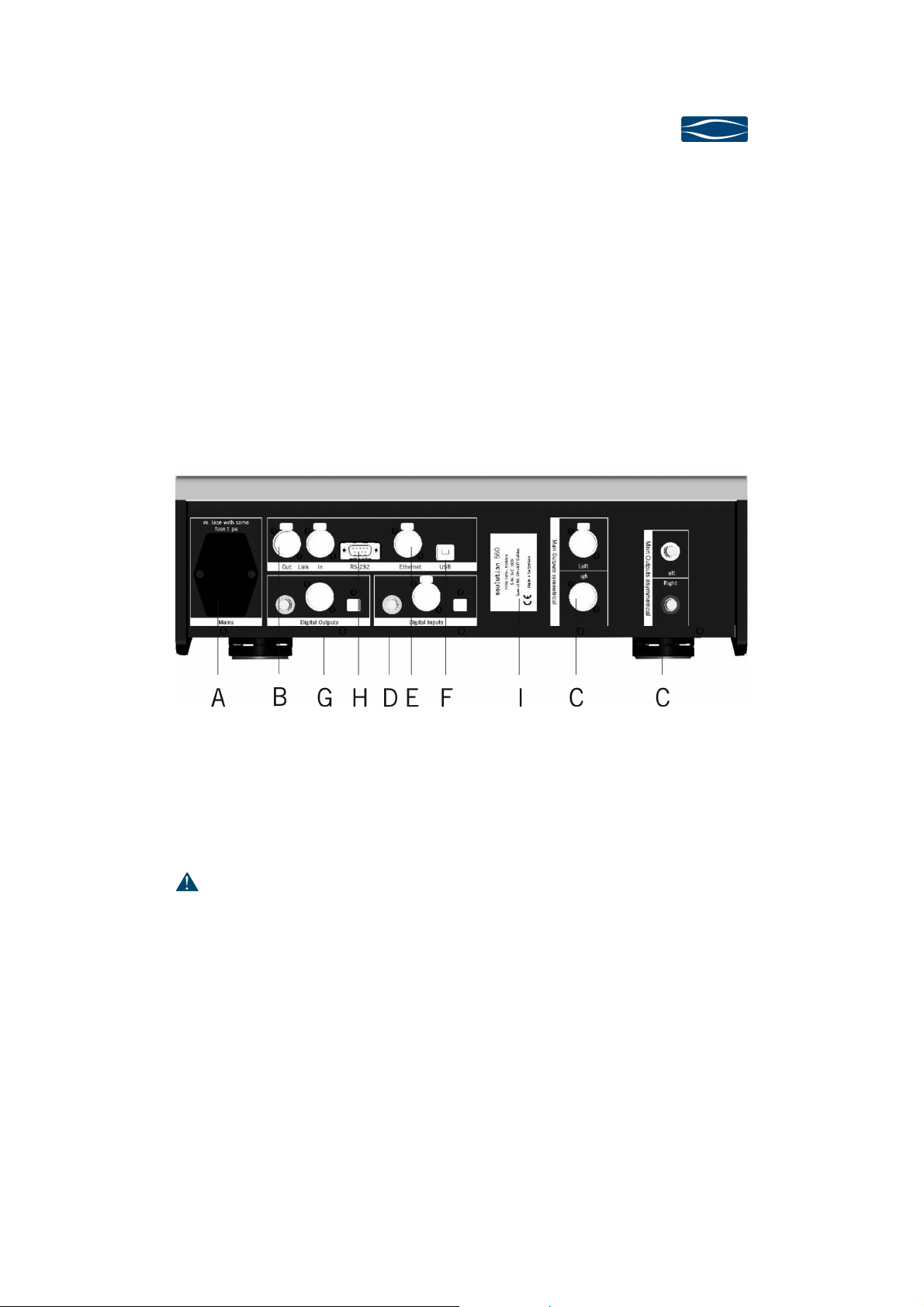
4Rear panel
Rear panelRear panel
Rear panel
Mains (A)
Mains (A)Mains (A)
Mains (A)
Connect the 560 D/A-Converter with the mains supply. In standby the 560 has a
power consumption o <0.5W (red LEDs in display).
Only switch
-
o the mains i your 560
D/A
-
Converter
is in standby.
LINK (B)
LINK (B)LINK (B)
LINK (B)
Connect the LINK-In o the 560 D/A-Converter with the LINK-Out o your soulution
preampli ier. LINK-Out allows including urther components in the LINK-network.

soulution
nature of sound
Seite 10
Output (C)
Output (C)Output (C)
Output (C)
Due to the extraordinary load-stability o the output-stage also long cables can be
used with no reduction o sound quality. For long cables we recommend using the
balanced connectors. For short cable lengths also unbalanced cables represent a
high quality connection, top quality cable and optimal layout prerequisite.
Digital
DigitalDigital
Digital-
--
-Input (D)
Input (D)Input (D)
Input (D)
The 560 D/A-Converter has three digital input connectors (SPDIF, AES/EBU and
Toslink). Digital data (PCM) up until 24Bit, 192kHz can be received.
LAN (E)
LAN (E)LAN (E)
LAN (E)
The 560 D/A-Converter can receive digital audio data rom your local area network.
It will be seen by media servers as „UPnP
TM
AV/DLNA Media Renderer device.
Following ile ormats are supported:
File
FileFile
File
ormat
ormatormat
ormat
Bit depth
Bit depthBit depth
Bit depth
Sampling
SamplingSampling
Sampling
rate
raterate
rate
FLAC (Free Losless Audio Codec)
16
-
24 bit
44.1
–
192 kHz
WAV (Wave orm Audio File Fo
r
mat)
16
-
24 bit
44.1
–
192 kHz
MP3 (Mpeg Audio Layer 3)
16
-
24 bit
44.1
–
192 kHz
ALAC (Apple Los
s
l
ess Audio Codec)
16
-
24 bit
44.1
–
192 kHz
AAC (Advanced A
u
dio Coding)
16
-
24 bit
44.1
–
192 kHz
AIFF (Audio Interchange File Fo
r
mat)
16
-
24 bit
44.1
–
192 kHz
DSF and DFF (DSD stream ile)
1 bit
2.82
–
5.64 MHz
DXD
(
Digital eXtr
e
me De ini
tion
)
24
bit
352.8 k
Hz

D/A
D/AD/A
D/A-
--
-Converter
ConverterConverter
Converter
560
560560
560
User manual
page 11
USB Audio (F)
USB Audio (F)USB Audio (F)
USB Audio (F)
The readable ile ormats depend mainly on the used player so tware. The ollowing
ormats can be received by the 560 D/A-Converter:
File
FileFile
File
ormat
ormatormat
ormat
Bit
BitBit
Bit
depth
depthdepth
depth
Sampling
SamplingSampling
Sampling
rate
raterate
rate
PCM (WAV, AIFF, FLAC; etc.)
16
-
24 bit
32
–
192 kHz
DSD (DoP)
1 bit
2.82
–
5.64 MHz
D
XD
24 bit
352.8 kHz
The 560 D/A-Converter supports USB Audio Class 2.0. For operating systems such
as Mac OS X, the 560 supports driver ree playback up to 24bits/192kHz. Under
Windows a speci ic USB Audio Class 2.0 driver is required or playback o iles with
sampling rates > 96kHz.
Digital
DigitalDigital
Digital-
--
-Output (G
Output (GOutput (G
Output (G)
))
)
The 560 D/A-Converter has 3 digital output connectors. (SPDIF (RCA), AES/EBU,
Toslink). Connect your avourite digital output with the digital input o your external
D/A-Converter. With the program- unction
4.1.1
4.1.14.1.1
4.1.1 RS 232
RS 232 RS 232
RS 232 Inter
InterInter
Inter ace
aceace
ace
(H
(H(H
(H)
))
)
The 560 D/A-Converter can be remote controlled through the RS232 inter ace. All
unctions can be controlled and relevant in ormation is provided to the control unit.
4.2
4.24.2
4.2 Type label (I)
Type label (I)Type label (I)
Type label (I)
The type label shows the serial number and the nominal power consumption.
soulution
nature of sound
Seite 12
4.3
4.34.3
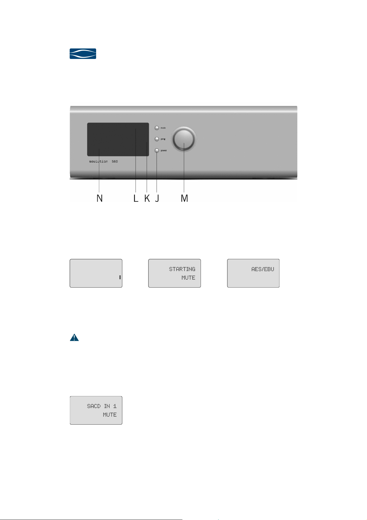
4.3 Front panel
Front panelFront panel
Front panel
4.3.1
4.3.14.3.1
4.3.1 Power
PowerPower
Power
(J
(J(J
(J)
))
)
The Power-button de ines the operating condition ON or OFF (red LEDs). The audio
circuits remain disconnected rom the outputs until it is switched on.
Display OFF condition Display during start-up Display in operation
We suggest switching the 560 D/A-Converter to standby (OFF) while not listening to
music. (Power consumption <0.5 W).
Unplug the 560
D/A
-
Converter
rom the mains be ore you manipulate with
cables, be ore cleaning, during thunder storms or be ore you
leave or longer
periods.
Mute (J)
Mute (J)Mute (J)
Mute (J)
Mute allows disconnecting all inputs rom the
outputs in case o an urgency (wrong cabling,
eedback loops, etc.).
D/A
D/AD/A
D/A-
--
-Converter
ConverterConverter
Converter
560
560560
560
User manual
page 13
Prog (K)
Prog (K)Prog (K)
Prog (K)
The 560 D/A-Converter can be adjusted to speci ic requirements o your system.
The Prog-button (de)activates the Programming-Mode.
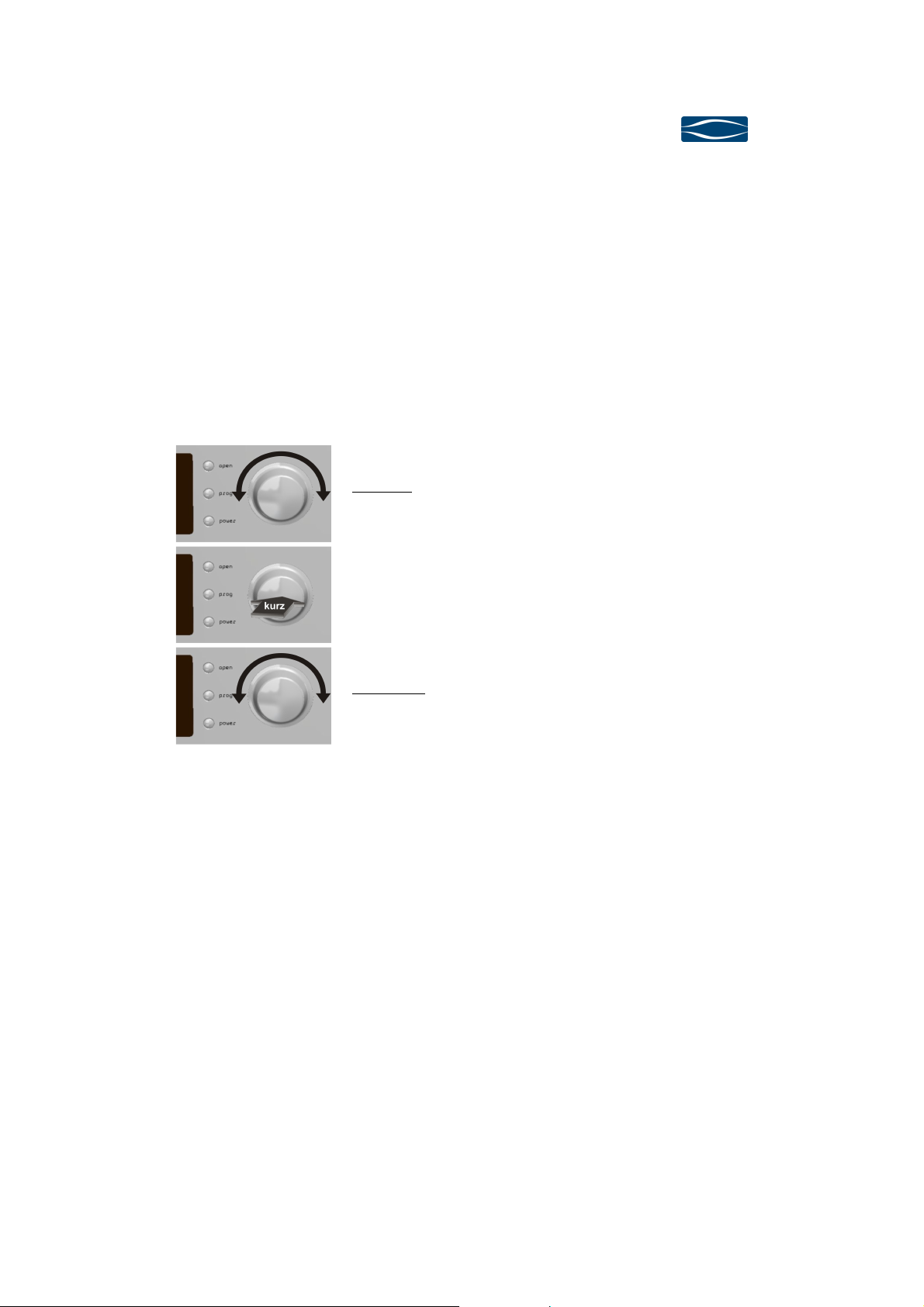
Volume (L)
Volume (L)Volume (L)
Volume (L)
The Volume knob controls the unctions Volume +/-, Input-Select and is used or
the Programming.
Input +/-
The desired input can be selected
Change to Volume mode
Volume +/-
Volume control
soulution
nature of sound
Seite 14
1
11
1Program
ProgramProgram
Program-
--
-Mode
ModeMode
Mode
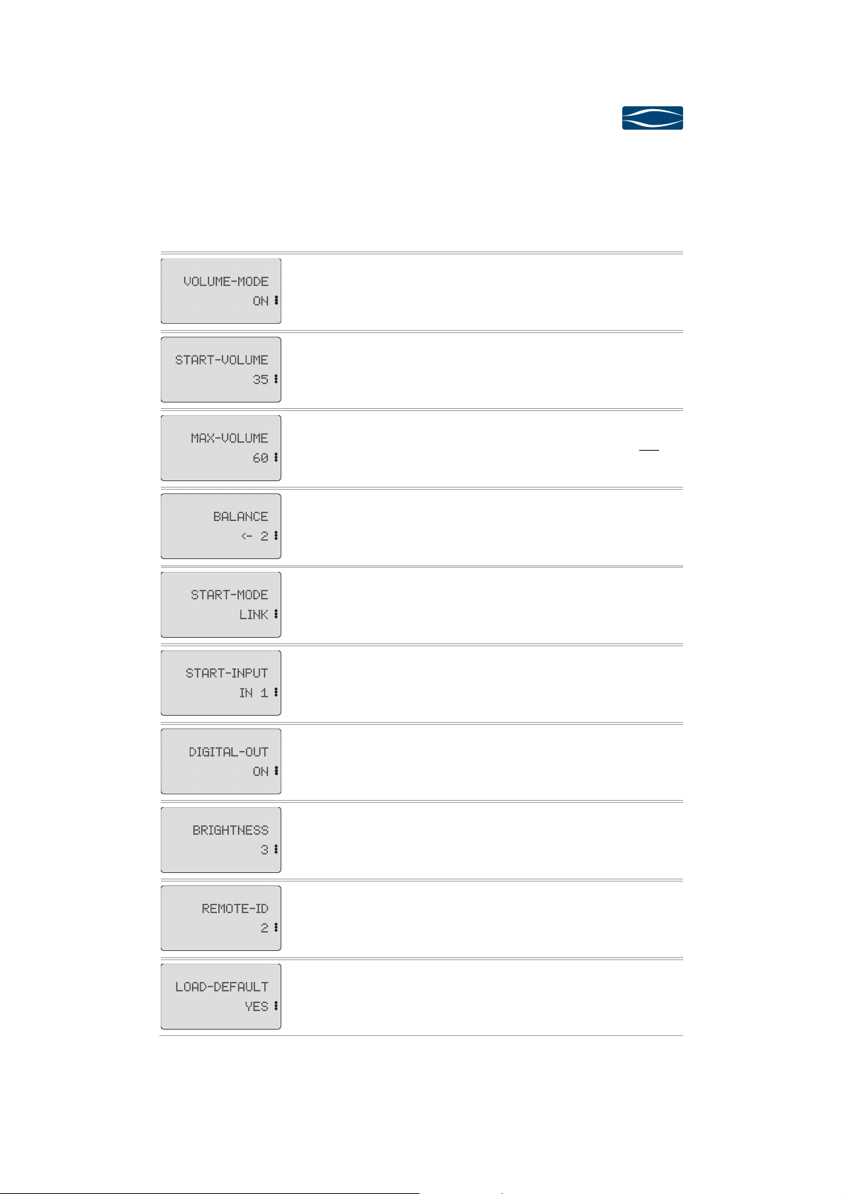
General
GeneralGeneral
General
The 560 D/A-Converter can be adjusted to your individual setup. It is already pro-
grammed with de ault settings. Further programming is not mandatory.
We recommend to adjust the Start-Volume and to set the Max-Volume.
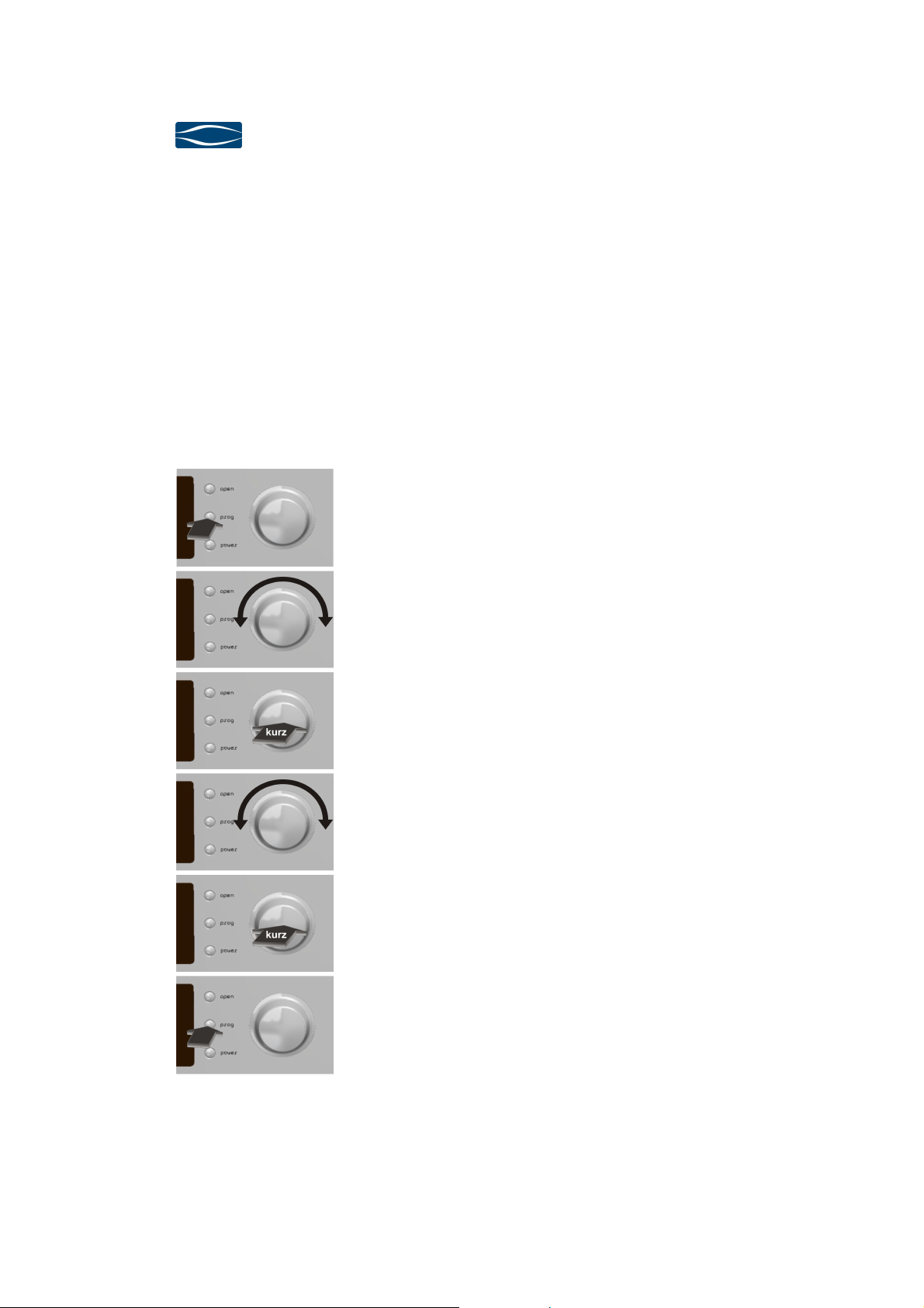
Function
FunctionFunction
Function
Push
PushPush
Push on the Prog button activates the Program-Mode.
Timeout a ter 10 seconds.
Rotating
RotatingRotating
Rotating o the Select knob allows selecting the desired
Program-Function
Push
PushPush
Push on the Select knob or approval o the selected
unction. Now the value domain o the selected Pro-
gram-Function is active. (red LEDs in display).
Rotating
RotatingRotating
Rotating o the Select knob allows or adjusting the de-
sired value.
Push
PushPush
Push on the Select knob or approval o the respective
value.
Push
PushPush
Push on the Prog button deactivates the Program-Mode.
Timeout a ter 10 seconds.
D/A
D/AD/A
D/A-
--
-Converter
ConverterConverter
Converter
560
560560
560
User manual
page 15
1.1
1.11.1
1.1 Program
ProgramProgram
Program-
--
-Func
FuncFunc
Function
tiontion
tions
ss
s
Fun
FunFun
Fun
c
cc
c
tion
tiontion
tion
Values
ValuesValues
Values
Remarks
RemarksRemarks
Remarks
ON,
ON,ON,
ON,
OFF
(
D
e)activate
s
the
Vo
l
ume
-
Mode
.
1..
30
3030
30
..50
De ines the Start
-
Volume level. In the
value domain it changes to the Start-
Volume level.
5
0...
80
8080
80
The maximal volume can be limited. In the
value domain the volume level does not
change.
<
-
9...
0
00
0
...9
-
>
De ines the level di erence b
e
tween le t
and right channel.
NORM
NORMNORM
NORM
,
LINK
NORM
OFF (Standby)
LINK Depending on Link System
SPDIF
SPDIFSPDIF
SPDIF
,AES/EBU,
Optical, USB,
Ethernet
De ines which input shall be active a ter
start-up.
OFF,
OFF,OFF,
OFF,
ON
(De)activates the digital outputs
1 = low
2 = medium
3 = high
3 = high3 = high
3 = high
Adjusts the brightness o the display
1
11
1
, 2
De in
es the
IR
identi ication o the 560.
The remote control has to be adjusted
accordingly
Loads
the de ault values
(bold)
(bold)(bold)
(bold)
or all
unctions.
soulution
nature of sound
Seite 16
2
22
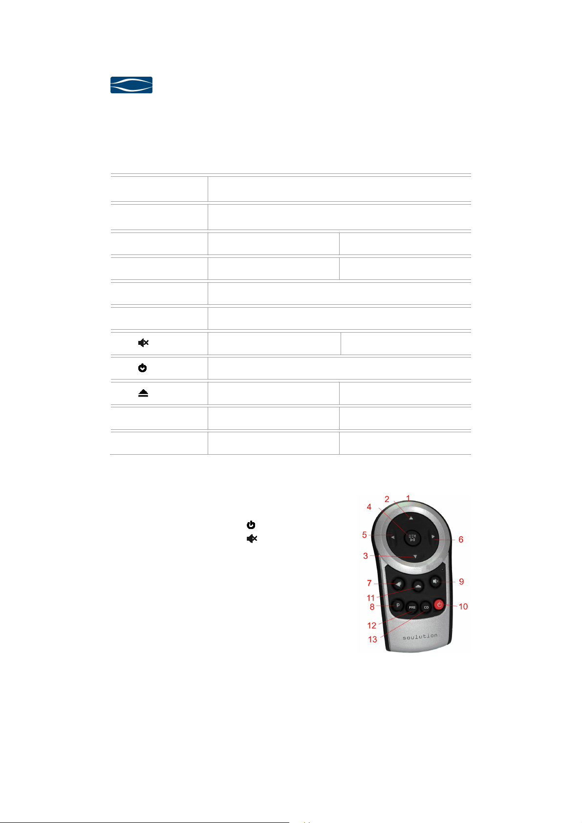
2Remote control
Remote controlRemote control
Remote control
Taste
TasteTaste
Taste
Pre
PrePre
Pre
/DAC
/DAC/DAC
/DAC
-
--
-
Mod
ModMod
Mod
e
ee
e
CD
CDCD
CD
-
--
-
Mod
ModMod
Mod
e
ee
e
(1)
(1)(1)
(1)
IR
IRIR
IR-
--
-transmitter
transmittertransmitter
transmitter
Operation until 5m distance and angel o ±45°.
(2,3)
(2,3)(2,3)
(2,3)
Volume +/-
(4)
(4)(4)
(4)
DIM /
DIM /DIM /
DIM /
Volume-Dim Play/Pause
(5/6)
(5/6)(5/6)
(5/6)
⊳
⊳⊳
⊳
Select +/- Next / Previous track
(7)
(7)(7)
(7)
Enter Function or Program-Mode
(8)
(8)(8)
(8)
P
P P
P
(De)activates Program-Mode
(9)
(9)(9)
(9)
Mute -
(10)
(10)(10)
(10)
ON / OFF
(11)
(11)(11)
(11)
- Open/Close
(12)
(12)(12)
(12)
PRE
PRE PRE
PRE
- Activates PRE-Mode
(13)
(13)(13)
(13)
CD
CD CD
CD
Activates CD-Mode -
Change o Remote Ctrl ID:
Press the respective buttons or approx. 5 seconds.
ID 1: ⊳
⊳⊳
⊳
(6),
(5),
(10)
ID 2: ⊳
⊳⊳
⊳
(6),
(5), (9)
Exchange o batteries (2 x AAA):
Open the battery tray on the rear side.
Insert the batteries into the tray as indicated.
Ensure correct polarity o the batteries.
Close the tray with corresponding screw.
Dispose the exhausted batteries

D/A
D/AD/A
D/A-
--
-Converter
ConverterConverter
Converter
560
560560
560
User manual
page 17
3
33
3Trouble shooting
Trouble shootingTrouble shooting
Trouble shooting
Error
ErrorError
Error
Action
ActionAction
Action
No display
No displayNo display
No display
Che
ck the cabling to the mains supply.
Eventually replace the use.
No music
No musicNo music
No music
Check
the cabling to the source components and the ampli ier.
i proper input has been selected
i the source component is in MUTE
i the ampli ier is switched on
POWER FAIL
POWER FAILPOWER FAIL
POWER FAIL
In case o a short circuit in the power supply the unit switc
h-
es o automatically. The display shows POWERFAIL.
OVERCURRENT
OVERCURRENTOVERCURRENT
OVERCURRENT
I the current at the output is higher than 0.2 A the MUTE
unction is activated and the display shows OVERCURRENT.
I you cannot identi y the error please disconnect the 560 D/A-Converter rom the
mains supply and contact your soulution dealer.
4
44
4Service
ServiceService
Service
I your soulution product needs service please contact your soulution dealer. For ur-
ther in ormation see www.soulution-audio.com

soulution
nature of sound
Seite 18
5
55
5Sa ety unctions
Sa ety unctionsSa ety unctions
Sa ety unctions
Overcurrent
OvercurrentOvercurrent
Overcurrent
For currents > 0.2 Ampere at the output the
560 D/A
-
Converter shuts down automatically.
Power supply
Power supplyPower supply
Power supply
The power supply is monitored or correct operation. In case o
an error the 560 gets shut down automatically.
Fus
FusFus
Fus
e
ee
e
Model 220
-
240 V
2A/T 250V micro use 5x20mm
Model 100-120 V 4A/T 250V micro use 5x20mm
6
66
6Warranty
WarrantyWarranty
Warranty
All soulution products are guaranteed against de ects in material and workmanship
or ive years rom date o purchase.
The guarantee is void i the product has been subject to misuse or negligence or has
been modi ied, repaired or opened by a non authorised person without written au-
thorisation o Spemot AG.
For the return transport to our premises please use exclusively the original packag-
ing. Transport damages are not subject to this guarantee, repairs will be charged.
We recommend e ecting transport insurance.
I you do not posses the original packaging no more please contact your soulution
dealer.
Basic repairs may be completed by your soulution dealer. Please clari y whether he
is able to do the work be ore you send the product back to us.

D/A
D/AD/A
D/A-
--
-Converter
ConverterConverter
Converter
560
560560
560
User manual
page 19
7
77
7Spec
SpecSpec
Speci
ii
i ication
icationication
ication
Nominal voltage
Nominal voltageNominal voltage
Nominal voltage
Model
220 – 240 V / 50 – 60 Hz 220 – 240 V
Model
100 – 120 V / 50 - 60 Hz 100 – 120 V
Power consumption
Power consumptionPower consumption
Power consumption
OFF (standby)
<0.5 W
ON
50 W
Main
MainMain
Main
-
--
-
Out
OutOut
Out
Output voltage
Balanced (XLR)
4 Vrms
Unbalanced (RCA)
2 Vrms
Peak Output Current
0.2 A
Impedance
10
Ω
Frequency response
DC-100 kHz
Distortion (THD)
<0.002 %
Signal to Noise Ratio
140 dB
Vo
lume range
0...-80 dB
Balance range
<- 9...0...9 -> dB
Digital
DigitalDigital
Digital
-
--
-
Out
OutOut
Out
Output
-Voltage
SPDIF
AES/EBU
500
5
mV p-p
V p-p
Output
-Impedance
SPDIF
AES/EBU
75
110
Ω
Ω
Digital
DigitalDigital
Digital
-
--
-
In
InIn
In
Sensitivity
0.3 - 5 V p-p
Input
-Impedance
SPDIF
AES/EBU
75
110
Ω
Ω
PLL
– control range
+/- 100 ppm
USB
USBUSB
USB
Input voltage
0.4 – 2.5 V
Data
24 bit / 192 kHz
Ethernet
EthernetEthernet
Ethernet
Input voltage
0.4 – 2.5 V
Data
24 bit / 192 kHz
LINK
LINKLINK
LINK
-
--
-
System
SystemSystem
System
+12
V
soulution
nature of sound
Seite 20
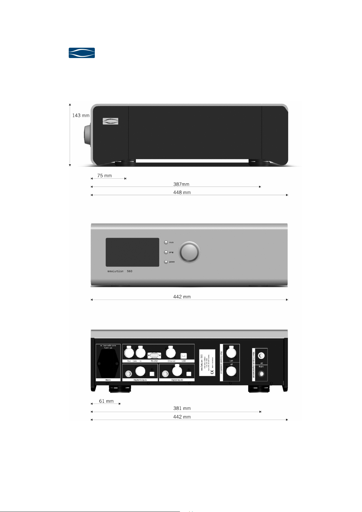
8
88
8Dimension
DimensionDimension
Dimensions
ss
s
Table of contents


