manuals.online logo
Brands
  1. Home
  2. •
  3. Brands
  4. •
  5. CTS
  6. •
  7. Media Converter
  8. •
  9. CTS MCT-5002FSMSFP+ User manual

CTS MCT-5002FSMSFP+ User manual

Other CTS Media Converter manuals

CTS MCT-3002 Series User manual

CTS

CTS MCT-3002 Series User manual

CTS CVT-2512 SERIES User manual

CTS

CTS CVT-2512 SERIES User manual

CTS CVT-3512 Series User manual

CTS

CTS CVT-3512 Series User manual

CTS WAC-2012 Series User manual

CTS

CTS WAC-2012 Series User manual

CTS MCT-3002 SERIES User manual

CTS

CTS MCT-3002 SERIES User manual

CTS MCT-RACK-12-MGM User manual

CTS

CTS MCT-RACK-12-MGM User manual

CTS MCT-3612 Series User manual

CTS

CTS MCT-3612 Series User manual

CTS MCT-3002 Series User manual

CTS

CTS MCT-3002 Series User manual

CTS MCT-RACK-18 User manual

CTS

CTS MCT-RACK-18 User manual

CTS CVT-3002-PLUS-DR SERIES User manual

CTS

CTS CVT-3002-PLUS-DR SERIES User manual

CTS CVT-3012SFP User manual

CTS

CTS CVT-3012SFP User manual

CTS IPC-3012 User manual

CTS

CTS IPC-3012 User manual

CTS CVT-3002-PLUS SERIES User manual

CTS

CTS CVT-3002-PLUS SERIES User manual

CTS CVT-100BTFC User manual

CTS

CTS CVT-100BTFC User manual

CTS HET-3012 SERIES User manual

CTS

CTS HET-3012 SERIES User manual

CTS WAC-2112 SERIES User manual

CTS

CTS WAC-2112 SERIES User manual

CTS WAC-3012 SERIES User manual

CTS

CTS WAC-3012 SERIES User manual

CTS IPC-3012 User manual

CTS

CTS IPC-3012 User manual

CTS CVT-3112 Series User manual

CTS

CTS CVT-3112 Series User manual

CTS MCT-100 Series User manual

CTS

CTS MCT-100 Series User manual

CTS MCT-5002SFP+ User manual

CTS

CTS MCT-5002SFP+ User manual

CTS CVT-3002-PLUS-DR Series User manual

CTS

CTS CVT-3002-PLUS-DR Series User manual

CTS CVT-3002-PLUS SERIES User manual

CTS

CTS CVT-3002-PLUS SERIES User manual

CTS WAC-3112 SERIES User manual

CTS

CTS WAC-3112 SERIES User manual

Popular Media Converter manuals by other brands

TR-Electronic CMS582M-4096/4096 IOL DMS 14H7 KRF Assembly instructions

TR-Electronic

TR-Electronic CMS582M-4096/4096 IOL DMS 14H7 KRF Assembly instructions

Korenix JetCon 2301S user manual

Korenix

Korenix JetCon 2301S user manual

StarTech.com ET91000LCOAM manual

StarTech.com

StarTech.com ET91000LCOAM manual

Alesis AI-3 Reference manual

Alesis

Alesis AI-3 Reference manual

Caton Vpro 5100 user guide

Caton

Caton Vpro 5100 user guide

Cypress CSC-5500 Operation manual

Cypress

Cypress CSC-5500 Operation manual

H&B TX-100 Installation and instruction manual

H&B

H&B TX-100 Installation and instruction manual

Bolin Technology D Series user manual

Bolin Technology

Bolin Technology D Series user manual

IFM Electronic Efector 400 RN30 Series Device manual

IFM Electronic

IFM Electronic Efector 400 RN30 Series Device manual

GRASS VALLEY KUDOSPRO ULC2000 user manual

GRASS VALLEY

GRASS VALLEY KUDOSPRO ULC2000 user manual

Linear Technology DC1523A Demo Manual

Linear Technology

Linear Technology DC1523A Demo Manual

Lika ROTAPULS I28 Series quick start guide

Lika

Lika ROTAPULS I28 Series quick start guide

Weidmuller IE-MC-VL Series Hardware installation guide

Weidmuller

Weidmuller IE-MC-VL Series Hardware installation guide

Optical Systems Design OSD2139 Series Operator's manual

Optical Systems Design

Optical Systems Design OSD2139 Series Operator's manual

Tema Telecomunicazioni AD615/S product manual

Tema Telecomunicazioni

Tema Telecomunicazioni AD615/S product manual

KTI Networks KGC-352 Series installation guide

KTI Networks

KTI Networks KGC-352 Series installation guide

Gira 0588 Series operating instructions

Gira

Gira 0588 Series operating instructions

Lika SFA-5000-FD user guide

Lika

Lika SFA-5000-FD user guide

manuals.online logo
manuals.online logoBrands
  • About & Mission
  • Contact us
  • Privacy Policy
  • Terms and Conditions

Copyright 2025 Manuals.Online. All Rights Reserved.

(Version 1.0)
Scenario 1-1: When one set of MCT-5002FSMSFP+ connects to two end
devices, and Signal Loss Alarm is “Disabled”on MCT-5002FSMSFP+.
In case there is a fault taken place on the fiber cable (See Fig. 1-1), the port link of FO1 will be
down due to the failure of receiving the optical signal. End Device #2 will also become
link-down because it cannot receive the optical signal transmitted from FO1 fiber port.
End Device #1 will link up due to the reason that it can continuously receive the optical signal
transmitted from FO2 fiber port through FO1 fiber port. Thus, the network administrator may be
unaware of the link fault. Actually, the total network cannot work normally.
Scenario 1-2: When one set of MCT-5002FSMSFP+ connects to two end
devices, and Signal Loss Alarm is “Enabled”on MCT-5002FSMSFP+.
In case there is a fault taken place on the fiber cable (See Fig. 1-2), the port link of FO1 will be
down due to the failure of receiving the optical signal, and the optical signal transmitted to End
Device#1 from FO2 fiber port through FO1 fiber port will be blocked as well. Thus, end devices
at both sides of MCT-5002FSMSFP+ will link down to alert the network administrator to do the
network troubleshooting immediately.
Fig. 1-1
Fig. 1-2
Introduction of MCT-5002FSMSFP+
Signal Loss Alarm Behavior (Version 1.0)
Signal Loss Alarm allows users to easily identify and diagnose the linking status by the signal loss status passed to end devices at both sides of MCT-5002FSMSFP+.
If Signal Loss Alarm is enabled (PIN 2 is set to ON), the fiber ports can link up only when both linking conditions are good. In addition, MCT-5002FSMSFP+ will simultaneously stop the optical signal
transmission at both sides when the signal loss occurs at one side. The fiber port links will be down to alert the user even the output of optical power exists. Configure Signal Loss Alarm DIP switch
as “Enabled” status, it provides users transparent link indication between two network devices interconnected by MCT-5002FSMSFP+.
If Signal Loss Alarm is disabled, MCT-5002FSMSFP+ will fail to transmit the optical signal to the port at the other side when the signal loss occurs at one side. The fiber link from this port will be
down even the output of optical power exists, and vice versa.
However, if the end device’s link up is based on the condition of optical power (e.g. EDFA), the fiber ports may link up due to the continuous output of optical power (No Loss of Power occurs) even
the signal loss occurs at one side of MCT-5002FSMSFP+.
The following scenarios illustrate the linking status of end devices with “Enabled” or “Disabled” Signal Loss Alarm of MCT-5002FSMSFP+.
(Version 1.0)
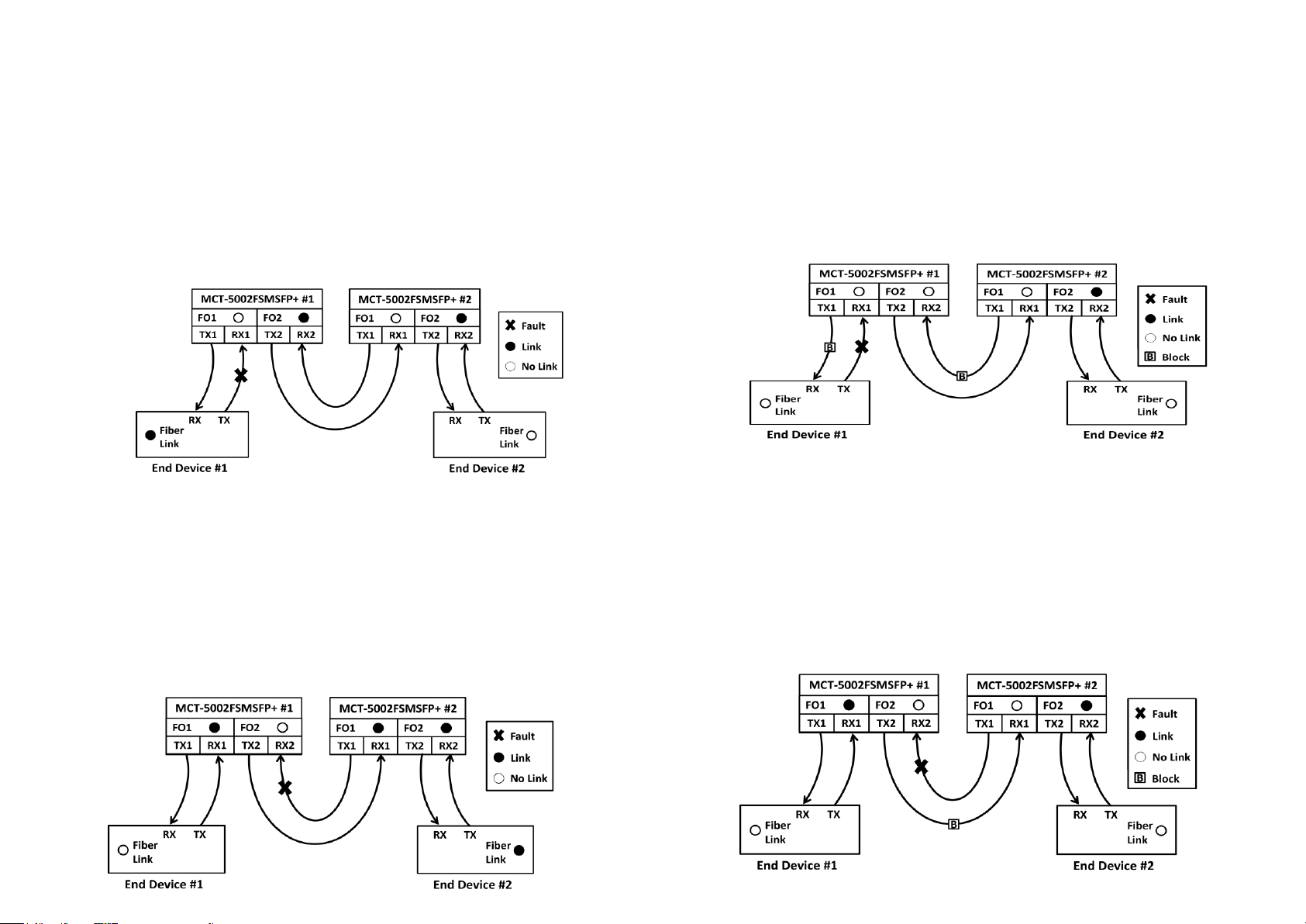
Scenario 2-1: When two sets of MCT-5002FSMSFP+ that link together connect
to one end device separately, and the link fault occurs on MCT-5002FSMSFP+
#1’s RX1 with “Disabled”Signal Loss Alarm.
In case there is a fault taken place on the fiber cable (See Fig. 2-1), the port link of FO1 on
MCT-5002FSMSFP+ #1 will be down due to the failure of receiving the optical signal. End
Device #2 will also become link-down because it cannot receive the optical signal transmitted
from FO1 fiber port of MCT-5002FSMSFP+ #1.
End Device #1 will link up due to the reason that it can continuously receive the optical signal
transmitted from FO2 fiber port of MCT-5002FSMSFP+ #2 through FO2 fiber port of
MCT-5002FSMSFP+ #1. Thus, the network administrator may be unaware of the link fault.
Actually, the total network cannot work normally.
Scenario 3-1: When two sets of MCT-5002FSMSFP+ that link together connect
to one end device separately, and the link fault occurs on MCT-5002FSMSFP+
#1’s RX2 with “Disabled”Signal Loss Alarm.
In case there is a fault taken place on the fiber cable (See Fig. 3-1), the port link of FO2on
MCT-5002FSMSFP+ #1 will be down due to the failure of receiving the optical signal. End
Device #1 will also become link-down because it cannot receive the optical signal transmitted
from FO2 fiber port of MCT-5002FSMSFP+ #1.
End Device #2 will link up due to the reason that it can continuously receive the optical signal
transmitted from FO1 fiber port of MCT-5002FSMSFP+ #1 through FO1 fiber port of
MCT-5002FSMSFP+ #2. Thus, the network administrator may be unaware of the link fault.
Actually, the total network cannot work normally.
Scenario 2-2: When two sets of MCT-5002FSMSFP+ that link together connect
to one end device separately, and the link Fault occurs on MCT-5002FSMSFP+
#1’s RX1 with “Enabled” Signal Loss Alarm.
In case there is a fault taken place on the fiber cable (See Fig. 2-2), the port link of FO1 on
MCT-5002FSMSFP+ #1 will be down due to the failure of receiving the optical signal. End
Device #2 will also become link-down because it cannot receive the optical signal transmitted
from FO1 fiber port of MCT-5002FSMSFP+ #1, and the optical signal transmitted to End
Device#1 from FO2 fiber port of MCT-5002FSMSFP+ #2 through FO2 fiber port of
MCT-5002FSMSFP+ #1 will be blocked as well. Thus, end devices at both sides will link down
to alert the network administrator to do the network troubleshooting immediately.
Scenario 3-2: When two sets of MCT-5002FSMSFP+ that link together connect
to one end device separately, and the link fault occurs on MCT-5002FSMSFP+
#1’s RX2 with “Enabled”Signal Loss Alarm.
In case there is a fault taken place on the fiber cable (See Fig. 3-2), the port link of FO2on
MCT-5002FSMSFP+ #1 will be down due to the failure of receiving the optical signal. End
Device #1 will also become link-down because it cannot receive the optical signal transmitted
from FO2 fiber port of MCT-5002FSMSFP+ #1, and the optical signal transmitted to End
Device#2 from FO1fiber port of MCT-5002FSMSFP+ #1 through FO1fiber port of
MCT-5002FSMSFP+ #2 will be blocked as well. Thus, end devices at both sides will link down
to alert the network administrator to do the network troubleshooting immediately.
Fig. 2-1
Fig. 3-2
Fig. 2-2
Fig. 3-1