SousVide Cucina Series User manual

USER MANUAL
Vacuum Packing Machine
Cucina Series
Art nr 0894605

2
USER MANUAL
Cucina Version: JUM-EN-C 01-07-16
© Copyright 2014

USER MANUAL
3
Cucina Version: JUM-EN-C 01-07-16
No part of this publication may be reproduced, stored in a retrieval system, or transmitted in any form
or by any electronic or mechanical means, or by photocopying, recording, or otherwise without the
prior written consent of SousVideTools.com

4
USER MANUAL
Cucina Version: JUM-EN-C 01-07-16
INTRODUCTION
SousVideTools.com is a supplier of ultra-modern vacuum packing machines.
Our machines are designed and manufactured to the highest standards. And that's clear. They
combine a sleek built and functional design with ease of use and durability. Installation is just a matter
of 'plug & pack' and the clever design ensures that the hygiene standards are maintained at all times.
This manual contains relevant information and instructions for installation, operation and maintenance
of the machine.
The machine is not suitable for the packaging of toxic, corrosive, irritant or
hazardous materials
All persons responsible for the operation must at least fully read and understand
the chapters on operation and safety of these operating instructions
All persons responsible for assembly, installation, maintenance and/or repair
should read and understand all of these instructions
The user is responsible for the interpretation and use of this manual in any
circumstances. Please contact the owner or the manager in case of questions or
doubts about the correct interpretation
This manual should be kept near the machine and should be within reach for
users
All major maintenance, adjustments to the machine and observations should be
recorded in a log, see Appendix 10.1
Changes to the installation/machine are not permitted without prior written
approval of the supplier
Please contact the vendor for special servicing that is not included in this manual
Comply at all times with the safety requirements, as specified in Chapter 3
The proper functioning and safety of the system can only be guaranteed if the
recommended maintenance is executed on time and correctly
Illustrations may differ from your machine

USER MANUAL
5
Cucina Version: JUM-EN-C 01-07-16
TABLE OF CONTENTS
LIST OF FIGURES.................................................................................................................................. 6
EC DECLARATION OF CONFORMITY (COPY) ................................................................................... 7
LIST OF SYMBOLS................................................................................................................................ 8
ICONS ..................................................................................................................................................... 9
1. TECHNICAL INFORMATION........................................................................................................ 10
2. DESCRIPTION OF THE MACHINE............................................................................................... 11
2.1. DESCRIPTION OF THE PACKAGING PROCESS /MACHINE FUNCTIONS..........................................................12
2.1.1. THE PACKAGING PROCESS /MACHINE FUNCTIONS ..................................................................................12
2.1.2. GENERAL FUNCTIONS .........................................................................................................................13
2.2. THE SEAL SYSTEM...............................................................................................................................13
2.3. DE VACUUM PUMP...............................................................................................................................15
2.4. ELECTRICAL INSTALLATION..................................................................................................................17
2.5. SINGLE PROGRAM DIGITAL CONTROL (SPDC)......................................................................................18
3. SAFETY ......................................................................................................................................... 20
3.1. GENERAL...........................................................................................................................................20
3.2. DURING NORMAL OPERATION ...............................................................................................................21
3.3. OPERATIONAL STAFF ..........................................................................................................................21
4. INSTALLATION............................................................................................................................. 22
4.1. TRANSPORT AND PLACEMENT ..............................................................................................................22
4.2. CONNECTING THE MACHINE..................................................................................................................22
4.3. START THE MACHINE FOR THE FIRST TIME ..............................................................................................22
5. OPERATION.................................................................................................................................. 23
5.1. STARTUP ...........................................................................................................................................23
5.2. PRODUCTION......................................................................................................................................23
5.3. CONTINUE TO THE NEXT STEP OF THE CYCLE..........................................................................................24
5.4. STOP PROGRAM..................................................................................................................................24
5.5. CHANGING THE PROGRAM SETTINGS .....................................................................................................25
5.5.1. SINGLE PROGRAM DIGITAL CONTROL (SPDC)......................................................................................25
5.5.1.1. EXTERNAL VACUUM OPTION (SPDC)....................................................................................................26
5.6. DIRECTIVE FOR FUNCTION VALUES........................................................................................................27
6. MAINTENANCE............................................................................................................................. 29
6.1. MAINTENANCE DIAGRAM......................................................................................................................29
6.2. CLEANING THE MACHINE......................................................................................................................30
6.3. OIL CLEANING PROGRAM .....................................................................................................................31
6.4. ADD OIL /CHANGE OIL .........................................................................................................................31
6.5. REPLACING THE EXHAUST FILTER (MAINTENANCE OF VACUUM PUMP) .......................................................33
6.6. REPLACING THE SEALING WIRE.............................................................................................................36
6.7. REPLACING THE SILICONE RUBBER ON THE SILICONE HOLDERS................................................................38
6.8. REPLACING THE LID GASKET ................................................................................................................39
7. TROUBLESHOOTING................................................................................................................... 40
8. WARRANTY CONDITIONS........................................................................................................... 41
8.1. LIABILITY ...........................................................................................................................................41
8.2. WARRANTY ........................................................................................................................................41
9. DISPOSE AS WASTE ................................................................................................................... 42
10. APPENDIX..................................................................................................................................... 43
10.1. LOG...................................................................................................................................................43

6
USER MANUAL
Cucina Version: JUM-EN-C 01-07-16
LIST OF FIGURES
FIGURE 1: OVERVIEW OF THE MAIN COMPONENTS...................................................................................... 11
FIGURE 2: OVERVIEW OF THE SEAL SYSTEM .............................................................................................. 13
FIGURE 3: OVERVIEW OF THE PUMP (FILTER COVER REMOVED) .................................................................. 16
FIGURE 4: OVERVIEW OF THE ELECTRICAL INSTALLATION ........................................................................... 17
FIGURE 5: CONTROL PANEL SINGLE PROGRAM DIGITAL CONTROL(SPDC)................................................. 18
FIGURE 6: CHANGING PARAMETERS (SPDC)............................................................................................. 25
FIGURE 7: EXTERNAL VACUUM ADAPTER KIT (SPDC)................................................................................. 26
FIGURE 8:WATER VAPOUR LINE ............................................................................................................... 28
FIGURE 9: REPLACING THE EXHAUST FILTER ON A 3-4 M3PUMP .................................................................. 33
FIGURE 10: REPLACING THE EXHAUST FILTER ON A 8M3POMP.................................................................... 34
FIGURE 11: REPLACING THE EXHAUST FILTER ON A 16M3POMP .................................................................. 35
FIGURE 12: REMOVING THE SEAL BAR....................................................................................................... 36
FIGURE 13: REPLACING THE SEALING WIRE ............................................................................................... 36
FIGURE 14: REPLACING THE SILICONE RUBBER OF THE SILICONE HOLDERS................................................. 38
FIGURE 15: REPLACING THE LID GASKET................................................................................................... 39

USER MANUAL
7
Cucina Version: JUM-EN-C 01-07-16
EC DECLARATION OF CONFORMITY (COPY)
We,
Gastronomy Plus Ltd. T/A SousVideTools.com
Central Barn, Hornby Road
Lancaster, LA2 9JX
United Kingdom
declare under our sole responsibility that the product;
Machine type: Cucina Series
fulfils all the relevant provisions of the directives
2006/42/EG Machinery Directive
2004/108/EG EMC-Directive
and is in conformity with the following standard(s) or other normative document(s);
NEN-EN-ISO 12100 Safety of machinery - general principles for design –Risk assessment and risk
reduction
NEN-EN 13857 Safety of machinery –Safety distances to prevent hazard zones being reached by
upper and lower limbs
NEN-EN 349 Safety of machinery –Minimum gaps to avoid crushing of parts of the human body
NEN-EN 953 Safety of machinery –Guards - General requirements for the design and construction of
fixed and movable guards
NEN-EN 13849-1 Safety of machinery –Safety-related parts of control systems - Part 1: General
principles for design
NEN-EN 60204-1 Safety of machinery –Electrical equipment of machines - Part 1: General requirements
The undersigned is authorized to compile the technical file
United Kingdom, 28 februari 2014
8
USER MANUAL
Cucina Version: JUM-EN-C 01-07-16
LIST OF SYMBOLS
For all operations in which the safety of the operator and/or technician is at stake and where caution
should be exercised, the following symbols are used.
Caution!
Danger:
High Voltage!
Tip:
Provides a quick overview or offers tips to make it easier to perform certain actions

USER MANUAL
9
Cucina Version: JUM-EN-C 01-07-16
ICONS
Some icons and warnings are included on the machine among others to indicate the possible risks
involved to the users.
ICON
DESCRIPTION
LOCATION
Nameplate
At the rear of the machine
Warning sign "HIGH VOLTAGE"
At the rear of the machine
Warning sign "HEAT"
On the sealbar(s)
On the vacuum pump
CAUTION!
Regularly check that the icons and markings are still clearly recognizable and
legible. Replace them if this is no longer the case
10
USER MANUAL
Cucina Version: JUM-EN-C 01-07-16
1. TECHNICAL INFORMATION
Jumbo
Mini
Jumbo
Jumbo
Plus
Jumbo
30
Jumbo
35
Jumbo
42
Jumbo
42XL
General
Ambient temperature
5 to 30
5 to 30
5 to 30
5 to 30
5 to 30
5 to 30
˚C
Noise production
< 70
< 70
< 70
< 70
< 70
< 70
dB(A)
Maximum daily production
5
5
5
5
5
5
h/day
Dimensions of the machine
Width
335
335
450
450
493
493
mm
Length
450
450
554
554
528
616
mm
Height
305/340*
305/340*
365
405
440
470
mm
Weight
25
30
35
48
56
67
kg
Maximum product height
85/130*
85/130*
150
150
180
180
mm
Electrical connection
Tension
**
**
**
**
**
**
V
Power
**
**
**
**
**
**
kVA
Vacuum pump
Capacity
4
8
8
16
16
16
m3/h
Oil
0.06
0.25
0.25
0.3
0.3
0.3
liter
Oil type
(Ambient temperature 5-40°C)
VM22
VM32
VM32
VM32
VM32
VM32
*depending on lid type. High or low lid
** See the nameplate

USER MANUAL
11
Cucina Version: JUM-EN-C 01-07-16
2. DESCRIPTION OF THE MACHINE
FUNCTION
This chapter provides an overview of the main components and functions
If detailed information is available in this guide, you will be redirected to the
specific sections
The performance of your machine may differ from the figure below
The figure below shows the main components of the system:
Figure 1: Overview of the main components
NO.
PART
DESCRIPTION
SECTION
1
Lid
The function of the lid is to close the chamber
during the vacuum cycle
The lid has a lid gasket fitted, which makes sure the
machine does not leak during the vacuum cycle
In the lid, silicone holder(s) are mounted as the
opposite of the sealing bar(s)
6.8
2.2, 6.7
2
Chamber
The products to be packed will be placed on the
worktable / in the chamber with the opening of the
vacuum seal bag on the seal position
3
Seal bar
In the chamber, depending on the version, 1 or 2
seal bars are mounted. With this/these the vacuum
bag is closed
2.2, 6.6
7
6
5
4
3
2
1

12
USER MANUAL
Cucina Version: JUM-EN-C 01-07-16
NO.
PART
DESCRIPTION
SECTION
4
Controlpanel
See section
2.5
5
Machine housing
The machine frame contains all necessary parts for
the correct functioning of the machine
6
Vacuum pump
See section
2.3
7
Power connection
See section
2.4
2.1. Description of the packaging process / machine functions
FUNTION
This chapter provides an overview of the process and the available machine
functions
In chapter 5.5 you will find information on how to set the parameters to the correct
values
2.1.1. The packaging process / machine functions
The following steps are taken during the process. For the detailed procedure, see Chapter 0
STEP
PROCESS PHASE
OPERATION
1
Preparations
The operator puts the product in a vacuum bag and
places it on the work top with the opening on the
seal bar
2
Extracting Vacuum
The vacuum process is started by closing the lid
During the cycle, the air will be removed from the
chamber until the set time has been reached
3
Sealing
The seal bars are pressed against the contra bars,
with the vacuum bag in between and melt the bag
to be closed
During the sealing, the material of the vacuum bag
is heated and compressed to form a hermetic
sealing. The function is programmed in seconds
As an option, a cutting wire is available. The
purpose of this wire is to remove the remaining foil
from the excess flap
4
Releasing vacuum
The vacuum is released, by letting air back into the
chamber
USER MANUAL
13
Cucina Version: JUM-EN-C 01-07-16
STEP
PROCESS PHASE
OPERATION
5
Open vacuum chamber
The lid opens
6
Remove the product
The operator can remove the packed product from
the worktable
2.1.2. General Functions
FUNCTION
ICON
OPERATION
Cleaning the pump
The pump cleaning program allows for a proper flushing of the
pump. During the program, the pump and the oil will reach the
operating temperature, so that the oil and the fluid will be
separated and that any contamination is filtered. The high
temperature takes care of evaporation of moisture in the pump,
which reduces the risk of corrosion
External vacuum
With this function vacuum can be applied to special food
packaging gastronorm containers outside the machine
The possibilities for adjusting the vacuum value are equal to the
standard vacuum (see 5.5.1.1 SPDC)
2.2. The seal system
FUNCTION
The seal system closes the opening(s) of the bag(s) to maintain the vacuum
and/or gas inside
The remaining flap can optionally be cut off by the seal bar
Figure 2: Overview of the seal system
3
2
1

14
USER MANUAL
Cucina Version: JUM-EN-C 01-07-16
NO.
PART
DESCRIPTION
SECTION
1
Seal bar
The seal bar consists of the following components
Seal wires: the sealing wires are heated for a
certain period of time so that the open side of the
vacuum bag will melt together during the sealing
Cutting wire (optional): a cutting wire is heated in
such a way that the foil of the bag partially melts
so that the top flap of the vacuum bag can be
torn off easily
Teflon-tape: sealing and cutting wires are coated
with Teflon tape to prevent the bag to stick to the
seal bar
Refer to the indicated section for detailed information
on maintenance
6.6
2
Silicon holder
Opposite to each seal bar a silicone holder is
mounted, which provides counter-pressure on the
cylinders / seal bag
6.7
3
Seal mechanism
The seal bars are pressed on the vacuum bag by
using cylinders or seal bags
By connecting the outside atmospheric pressure to
the inlet of the cylinders, they will press the seal bar
on the bag
2.2

USER MANUAL
15
Cucina Version: JUM-EN-C 01-07-16
2.3. De vacuum pump
FUNCTION
The vacuum pump creates a vacuum in the chamber
3 en 4 m3
8 m3
5
4
3
2
1
5
4
3
2
1

16
USER MANUAL
Cucina Version: JUM-EN-C 01-07-16
16 m3
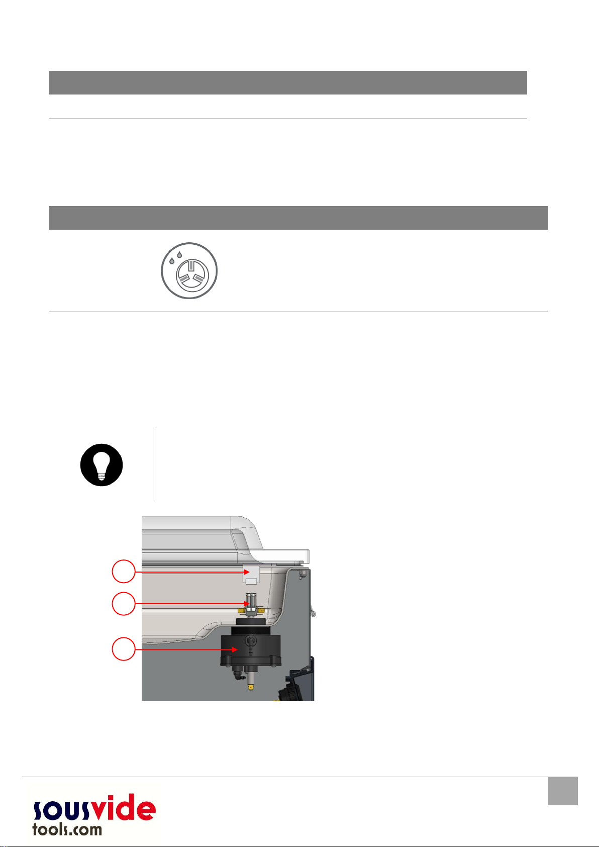
Figure 3: Overview of the pump (filter cover removed)
NO.
PART
DESCRIPTION
SECTION
1
Vacuum pump
Creates the vacuum during the process
6.1
2
Exhaust filter
Filters the exhaust air and absorbs oil vapors
Refer to the indicated section for detailed information
with regards to maintenance
6.1
3
Oil sight glass
The oil sight glass indicates the maximum and
minimum oil level in the vacuum pump
The oil sight glass is visible when te cover of the
machine is in place
6.1
4
Oil drain plug
To drain the oil
5
Oil filler plug
To fill the pump with oil
5
4
3
2
1

USER MANUAL
17
Cucina Version: JUM-EN-C 01-07-16
2.4. Electrical installation
FUNCTION
The electrical installation provides power to the vacuum pump, sealing system
and control unit
See the electrical diagram for the further structure and operation of the electrical
installation. For the electrical diagram, please contact your dealer
ATTENTION!
Work on the electrical installation may only be carried out by a technical expert
Figure 4: Overview of the electrical installation
The machine consists of the following components
NO.
PART
DESCRIPTION
SECTION/
LOCATION
1
Power cable
To connect the power supply to the machine
2
Control panel
The available control functions can be used
Your machine has the following control type:
oSingle Program Digital Control (SPDC)
2.5
2
1

18
USER MANUAL
Cucina Version: JUM-EN-C 01-07-16
2.5. Single Program Digital Control (SPDC)
FUNCTION
The machine can be operated
The program can be modified
See chapter 0 for instructions on operation and programming
Figure 5: Control panel Single Program Digital Control(SPDC)
NO.
ELEMENT
EXPLANATION
1
On / Off button
This button turns the machine on/off
2
Cursor key
Navigates you through the functions shown in the display 4/5
3
”Oil cleaning program”
key
Operate the key to activate the pump cleaning program. This
removes moisture from the oil in the vacuum pump. Moisture
can be absorbed by the oil when the pump is only running
short cycles or when you pack products containing moisture
See 6.3 for instructions
4
Display parameter
Displays the current value of the active function during the
program cycle or the set value of the selected function when
the machine is idle
5
Function display
The LED light for the function illuminates when the function is
active during the program cycle or when the function is
selected in the programming mode
6
“-/stop” key
The 'stop' key can be used during a packing cycle to interrupt
the full cycle. All functions are cancelled, and the cycle will be
terminated
In the programming mode this key decreases the value of the
selected parameter
8
7
6
5
4
3
2
1

USER MANUAL
19
Cucina Version: JUM-EN-C 01-07-16
NO.
ELEMENT
EXPLANATION
7
“+/stop vacuum” key
Stops the current function and continues with the next program
step
In the programming mode this key decreases the value of the
selected parameter
8
Vacuum gauge
Shows the pressure in the vacuum chamber
A value of -1 bar corresponds to 99% vacuum

20
USER MANUAL
Cucina Version: JUM-EN-C 01-07-16
3. SAFETY
3.1. General
ATTENTION!
Never pack products that can be damaged by vacuum
Never pack living animals
Warranty and/or liability expires if any damage is caused by repairs and/or
modifications that are not authorized by the supplier or any of its distributors
In case of malfunction, contact the supplier
High pressure cleaning is not allowed. This can cause damage to the electronics
and other components
Prevent water from entering the ventilation inlet of the chamber or through the
vent of the pump. This causes irreversible damage to the pump
The work space around the machine must be safe. The owner of the machine
must take the necessary precautions to operate the machine safely
It is forbidden to start the machine in an explosive environment
The machine was designed in such a way that production is safe under normal
ambient conditions
The owner of the machine must check that the instructions in this manual are
monitored effectively
The securing devices must not be removed
The correct operation and safety of the system can only be guaranteed when the
maintenance is performed correctly and on time, as prescribed
If work on the machine must be carried out, it must be disconnected and blocked
from the power supply
DANGER
Only authorized persons, designated by the owner, may perform work on the
electrical installation
Ensure, by means of internal procedures and monitoring, that all relevant power
supplies are disconnected
The machine should not be used during cleaning, inspection, repair and
maintenance and must be disconnected from the power supply using the plug
Never perform welding work on the machine without disconnecting the cable
connection to the electrical components first
Never use the power supply of the control unit to connect to other machines
All electrical connections must be connected to the terminal strip according to
the wiring diagram
This manual suits for next models
6
Table of contents
Other SousVide Kitchen Appliance manuals


