South Bend Tools SB1124F User manual
®
A Tradition of Excellence
South Bend Tools
© January, 2023 by South Bend Tools For Machines Mfd. Since 11/22 (V1.06.23)
MODEL SB1124F
9" X 48" 3 HP VARIABLE-SPEED
TURRET MILL W/DRO
OWNER'S MANUAL
***Keep for Future Reference***

Customer Service
We stand behind our machines. If you have any service questions, parts requests or general questions
about your purchase, feel free to contact us.
South Bend Tools
P.O. Box 2027
Bellingham, WA 98227
Phone: (360) 734-1540
Fax: (360) 676-1075 (International)
Fax: (360) 734-1639 (USA Only)
Email: [email protected]
Updates
For your convenience, any updates to this manual will be available to download free of charge
through our website at:
www.southbendtools.com
Scope of Manual
This manual helps the reader understand the machine, how to prepare it for operation, how to control
it during operation, and how to keep it in good working condition. We assume the reader has a basic
understanding of how to operate this type of machine, but that the reader is not familiar with the
controls and adjustments of this specific model. As with all machinery of this nature, learning the
nuances of operation is a process that happens through training and experience. If you are not an
experienced operator of this type of machinery, read through this entire manual, then learn more
from an experienced operator, schooling, or research before attempting operations. Following this
advice will help you avoid serious personal injury and get the best results from your work.
Manual Feedback
We've made every effort to be accurate when documenting this machine. However, errors sometimes
happen or the machine design changes after the documentation process—so
the manual may not
exactly match your machine.
If a difference between the manual and machine leaves you in doubt,
contact our
customer service for clarification.
We highly value customer feedback on our manuals. If you have a moment, please share your
experience using this manual. What did you like about it? Is there anything you would change to
make it better? Did it meet your expectations for clarity, professionalism, and ease-of-use?
South Bend Tools
C
/O Technical Documentation Manager

Table of Contents
INTRODUCTION...............................................................2
Left Front View Identification ............................2
Right Front View Identification .......................... 3
Description of Controls & Components ..............4
Product Specifications ......................................... 7
SAFETY............................................................................. 10
Understanding Risks of Machinery ..................10
Basic Machine Safety ........................................10
Additional Milling Machine Safety................... 12
PREPARATION .............................................................. 13
Preparation Overview........................................ 13
Required for Setup............................................. 13
Power Supply Requirements.............................14
Converting Voltage to 440V ..............................16
Unpacking ..........................................................17
Inventory ............................................................17
Cleaning & Protecting ....................................... 18
Location ..............................................................19
Lifting & Moving................................................20
Leveling & Mounting......................................... 21
Anchoring to Floor ............................................. 21
Assembly ............................................................22
Power Connection (220V) ..................................24
Power Connection (440V) ..................................24
Initial Lubrication .............................................25
Test Run .............................................................26
Spindle Break-In................................................ 29
Inspections & Adjustments ............................... 29
OPERATION....................................................................30
Operation Overview........................................... 30
Table Movement.................................................31
Head Movement .................................................33
Ram Movement ..................................................34
Spindle Speed..................................................... 35
Spindle Downfeed ..............................................38
Using Spindle Brake.......................................... 42
Loading/Unloading Tooling ...............................42
ACCESSORIES.............................................................. 44
MAINTENANCE ............................................................. 48
Maintenance Schedule....................................... 48
Cleaning & Protecting ....................................... 48
Lubrication......................................................... 50
Machine Storage ................................................54
SERVICE........................................................................... 55
Coolant Reservoir...............................................55
Tramming Spindle .............................................57
Adjusting Gibs....................................................59
Adjusting Leadscrew Backlash ......................... 60
TROUBLESHOOTING................................................. 62
ELECTRICAL................................................................... 65
Electrical Safety Instructions ...........................65
Electrical Overview............................................ 66
Electrical Cabinet ..............................................67
Electrical Cabinet Wiring Diagram (220V) ...... 68
Electrical Cabinet Wiring Diagram (440V) ...... 69
Control Panel .....................................................70
Main Motor Wiring Diagrams........................... 71
DRO Wiring Diagram ........................................ 72
Power Feed Wiring Diagram.............................72
Electrical Component Photos ............................ 73
PARTS................................................................................ 74
Belt Housing.......................................................74
Gearbox ..............................................................76
Headstock........................................................... 78
Column, Knee & Ram........................................81
Table ...................................................................84
One Shot Oiler ...................................................86
Coolant System ..................................................87
Electrical Cabinet ..............................................88
Control Box.........................................................89
Accessories .........................................................90
Machine Labels (Front) .....................................91
Machine Labels (Side) ....................................... 92
WARRANTY..................................................................... 93

-2-
For Machines Mfd. Since 11/22
South Bend Tools
Model SB1124F INTRODUCTION
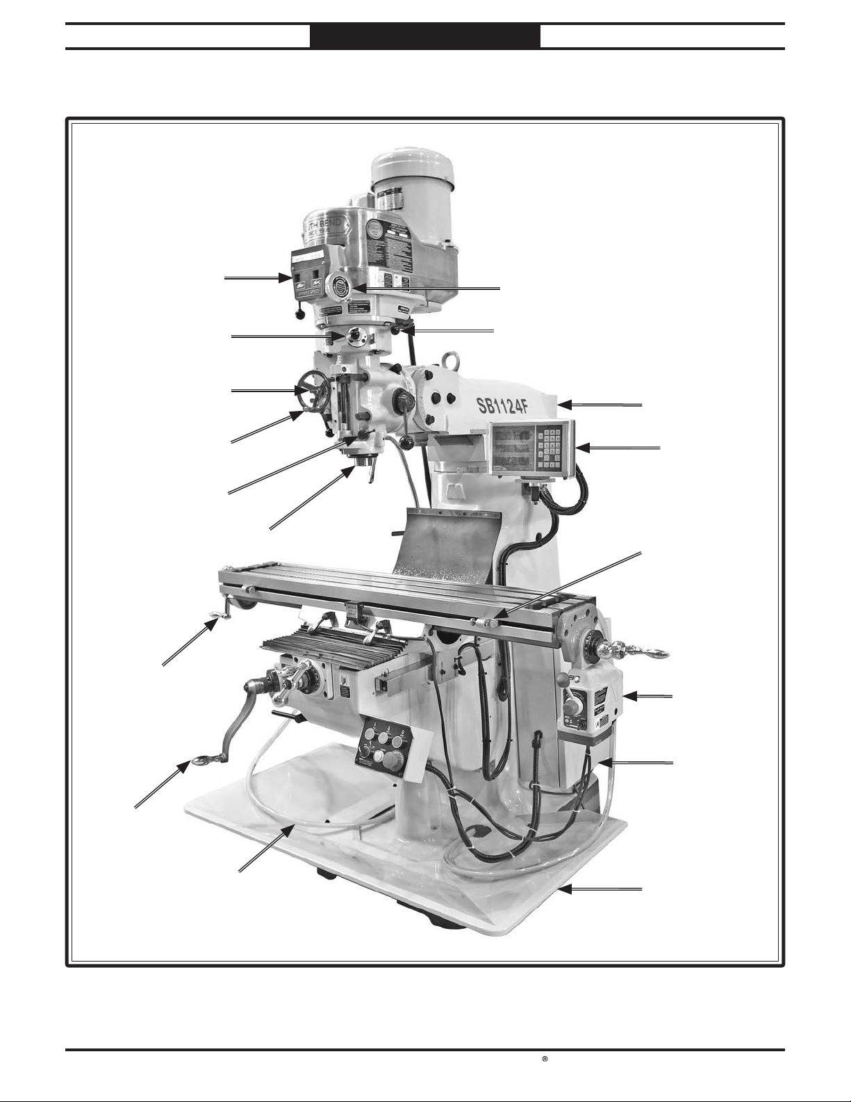
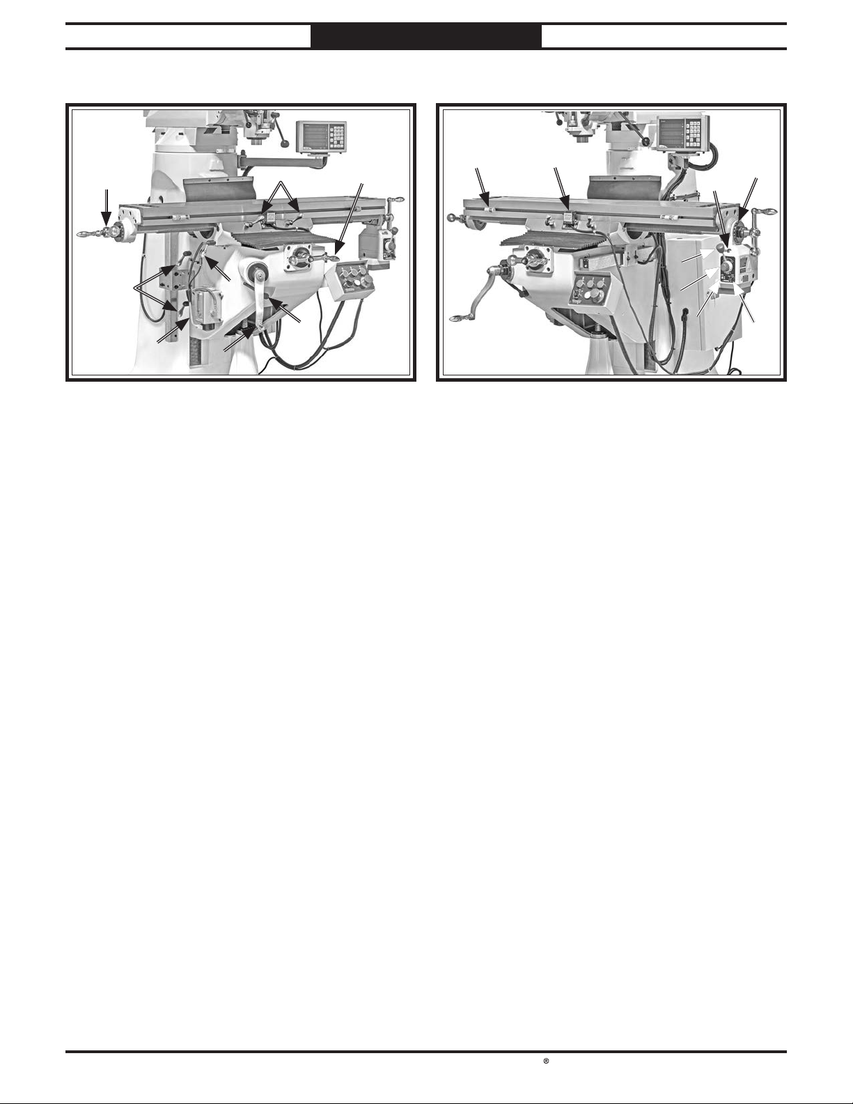
Left Front View Identification
Introduction
MotorMotor
Spindle Brake LeverSpindle Brake Lever
KneeKnee
X-Axis TableX-Axis Table
Lock (1 of 2)Lock (1 of 2)
Z-Axis TableZ-Axis Table
Lock (1 of 2)Lock (1 of 2)
Fine Downfeed Clutch LeverFine Downfeed Clutch Lever
Coolant ValveCoolant Valve
& Nozzle& Nozzle
One ShotOne Shot
OilerOiler
Y-Axis BallY-Axis Ball
HandleHandle
AdjustableAdjustable
Downfeed StopDownfeed Stop
9090°°Positive StopPositive Stop
Y-AxisY-Axis
TableTable
LockLock
Control PanelControl Panel
Auto DownfeedAuto Downfeed
Rate SelectorRate Selector
X-Axis LimitX-Axis Limit
SwitchSwitch
CoarseCoarse
DownfeedDownfeed
LeverLever
Knee CrankKnee Crank
Lock LeverLock Lever
High-RangeHigh-Range
Variable-SpeedVariable-Speed
IndicatorIndicator
Belt HousingBelt Housing
HeadstockHeadstock
South Bend Tools
For Machines Mfd. Since 11/22 Model SB1124F
-3-
INTRODUCTION
Right Front View Identification
RamRam
X-Axis BallX-Axis Ball
Handle (1 of 2)Handle (1 of 2)
Quill and SpindleQuill and Spindle
DRODRO
Fine DownfeedFine Downfeed
HandwheelHandwheel
Splash PanSplash Pan
X-AxisX-Axis
Power FeedPower Feed
Quill LockQuill Lock
LeverLever
Variable-Speed HandwheelVariable-Speed Handwheel
Auto DownfeedAuto Downfeed
Direction PinDirection Pin
Coolant ReturnCoolant Return
HoseHose
Manual/PowerManual/Power
Downfeed SelectorDownfeed Selector
Spindle SpeedSpindle Speed
Range SelectorRange Selector
ElectricalElectrical
BoxBox
X-AxisX-Axis
Limit StopLimit Stop
(1 of 2)(1 of 2)
KneeKnee
CrankCrank
Low-RangeLow-Range
Variable-SpeedVariable-Speed
IndicatorIndicator
-4-
For Machines Mfd. Since 11/22
South Bend Tools
Model SB1124F INTRODUCTION
Description of Controls
& Components
Refer to Figures 1–6and the following
descriptions to become familiar with the basic
controls and components used to operate this
machine.
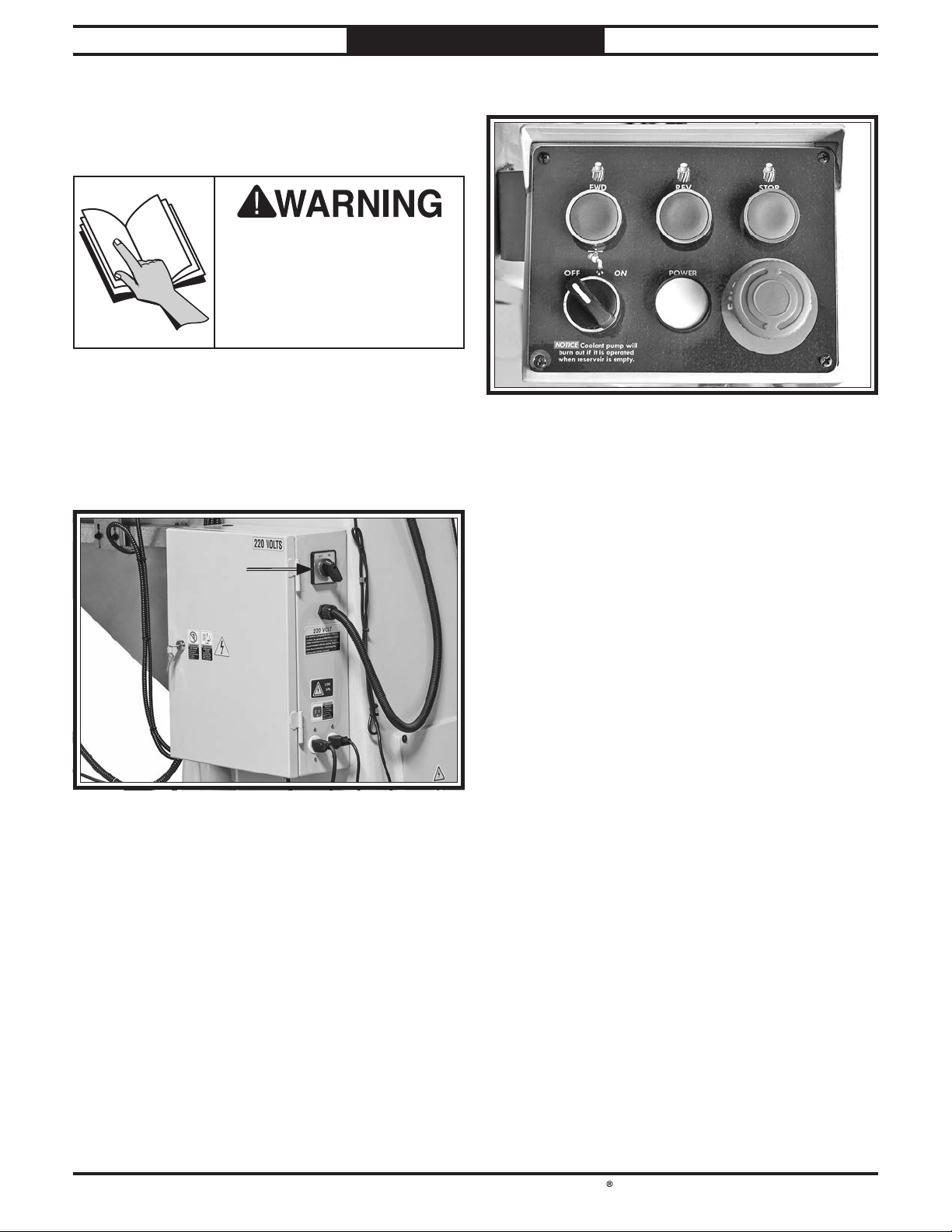
Master Power Switch
A. Master Power Switch: Turns incoming power
ON and OFF.
To reduce the risk of
serious injury when using
this machine, read and
understand this entire
manual before beginning any
operations.
Figure 1. Location of master power switch.Location of master power switch.
AA
Control Panel
B. FWD Button: Starts spindle forward rotation
(clockwise looking down on headstock).
C. REV Button: Starts spindle reverse
rotation (counterclockwise looking down on
headstock).
D. Stop Button: Stops spindle rotation.
E. Coolant Pump ON/OFF Switch: Turns
coolant pump ON and OFF.
F. POWER Light: Illuminates when power to
machine is enabled.
G. EMERGENCY STOP Button: Disables power
to control panel and stops all machine
functions when pressed. To reset, twist
button clockwise until it pops out.
Figure 2. Control panel.Control panel.
DD
EEFF
BBCC
GG
South Bend Tools
For Machines Mfd. Since 11/22 Model SB1124F
-5-
INTRODUCTION
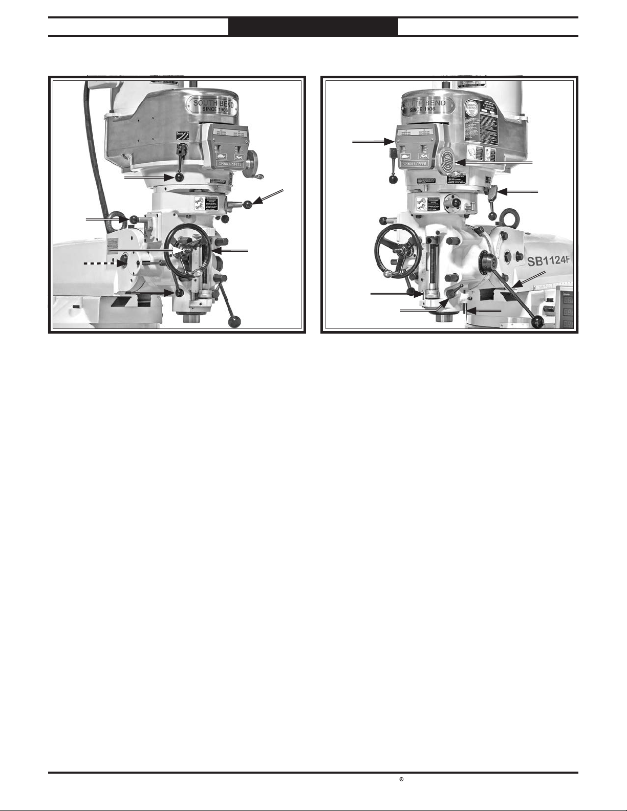
Headstock (Left)
H. Spindle Brake Lever: Quickly stops spindle
AFTER power to spindle is turned OFF.
I. Manual/Power Downfeed Selector: Selects
between manual and power downfeed.
J. Fine Downfeed Handwheel: Manually
controls slow spindle downfeed for fine Z-axis
control.
K. Fine/Auto Downfeed Clutch Lever: Engages
fine/auto-downfeed gears.
L. 90° Positive Stop: Stops headstock at 90°to
table following tilt procedure.
M. Auto-Downfeed Direction Pin: Starts, stops,
and reverses auto-downfeed direction.
N. Auto-Downfeed Rate Selector: Selects one of
the three auto-downfeed rates:
• 0.0015 in./rev.
• 0.003 in./rev.
• 0.006 in./rev.
O. Variable-Speed Indicators: Indicate spindle
speed in high and low ranges.
Headstock (Right)
P. Variable Speed Handwheel: Selects desired
spindle speed within high or low range.
Q. Spindle Speed Range Selector: Engages
back gear for low (60 RPM–500 RPM), and
disengages back gear for high (500 RPM–
4200 RPM) spindle speed ranges.
Note: When engaged, back gear reverses
spindle rotation, causing spindle FWD/REV
buttons to be reversed in low range.
R. Coarse Downfeed Lever: Quickly moves
quill downward manually and automatically
retracts spindle to top position when
released. Typically used for drilling
operations.
S. Dial Indicator Rod: Used to hold dial test
indicator when tramming spindle.
T. Quill Lock Lever: Locks quill in vertical
position.
U. Adjustable Downfeed Stop: Limits depth of
quill travel. Dial is graduated in increments
of 0.001". Typically used for repeat
operations.
Figure 3. Headstock controls (left).Headstock controls (left).
JJ
KK
LL
NN
MM
HHII
Figure 4. Headstock controls (right).Headstock controls (right).
PP
QQ
RR
TT
UU
SS
OO
-6-
For Machines Mfd. Since 11/22
South Bend Tools
Model SB1124F INTRODUCTION
Table
V. X-Axis Table Locks: Tighten to prevent
X-axis table movement for increased rigidity
during operations where X-axis should not
move.
W. Y-Axis Ball Handle: Manually moves table
along Y-axis (front and back).
X. Knee Crank Lock Lever: Tightens to prevent
accidental movement of knee crank.
Y. Knee Crank: Manually moves table along
Z-axis (up and down).
Z. Y-Axis Table Lock: Tightens to prevent
Y-axis table movement for increased rigidity
during operations where Y-axis should not
move.
AA. One Shot Oiler: Lubricates X-, Y-, and Z-axis
table ways.
AB. Z-Axis Table Locks: Tighten to prevent Z-axis
table movement for increased rigidity during
operations where Z-axis should not move.
AC. X-Axis Ball Handle (1 of 2): Manually moves
table along X-axis (left and right).
AD. Limit Stop (1 of 2): Restricts table movement
by its positioning along front of table.
AE. Limit Switch: Stops table movement when
either of the switch side plungers are pressed
by limit stops.
AF. Rapid Traverse Button: When pressed, moves
table at full speed when already in motion.
AG. Graduated Index Ring: Displays distance of
table travel in 0.001" increments, with one
full revolution equal to 0.200" of table travel.
AH. Power Feed ON/OFF Switch: Turns power
feed ON and OFF.
AI. Reset Button: Resets internal circuit breaker
if unit is overloaded and shuts down.
AJ. Speed Dial: Controls speed of power feed.
Rotating dial increases/decreases speed.
AK. Direction Lever: Selects direction of table
movement. Middle position is neutral.
X-Axis Power Feed
Figure 5. Table controls.Table controls.
VVWW
YY
XX
AAAA
ZZ
ABAB
ACAC
Figure 6. X-Axis power feed controls.X-Axis power feed controls.
ADAD AEAE
AFAF AGAG
AJAJ
AIAI AHAH
AKAK

South Bend Tools
For Machines Mfd. Since 11/22 Model SB1124F
-7-
INTRODUCTION
Product Specifications
Model SB1124F Page 1 of 3
Model SB1124F
9" x 48" 3 HP Variable‐Speed Turret Mill With
DRO
Product Dimensions
Weight........................................................................................................................................................... 2315 lbs.
Width (side-to-side) x Depth (front-to-back) x Height..................................................................... 64 x 57 x 84 in.
Footprint (Length x Width)....................................................................................................................... 24 x 36 in.
Space Required for Full Range of Movement (Width x Depth)............................................................... 95 x 63 in.
Shipping Dimensions
Type.......................................................................................................................................................... Wood Crate
Content.......................................................................................................................................................... Machine
Weight........................................................................................................................................................... 2625 lbs.
Length x Width x Height................................................................................................................... 66 x 59 x 77 in.
Electrical
Power Requirement.................................................................................................... 220V or 440V, 3-Phase, 60 hz
Prewired Voltage................................................................................................................................................ 220V
Full-Load Current Rating.............................................................................................. 9.6A at 220V, 4.8A at 440V
Minimum Circuit Size..................................................................................................... 15A at 220V, 15A at 440V
Connection Type.............................................................................. Cord at 220V, Permanent (Hardwire) at 440V
Power Cord Included.............................................................................................................................................. No
Recommended Power Cord............................................................................. "S"-Type, 4-wire, 14 AWG, 300 VAC
Plug Included.......................................................................................................................................................... No
Recommended Plug Type................................................................................................................... 15-20 for 220V
Switch Type....................................................................................... Control Panel w/Magnetic Switch Protection
Motors
Main
Horsepower............................................................................................................................................... 3 HP
Phase.................................................................................................................................................... 3-Phase
Amps........................................................................................................................... 8A at 220V, 4A at 440V
Speed................................................................................................................................................ 1720 RPM
Type........................................................................................................................................ TEFC Induction
Power Transfer .......................................................................................................................................... Belt
Bearings................................................................................................ Shielded & Permanently Lubricated
Coolant Pump
Horsepower............................................................................................................................................ 1/8 HP
Phase.................................................................................................................................................... 3-Phase
Amps.................................................................................................................. 0.4 A at 220V, 0.23A at 440V
Speed................................................................................................................................................ 3450 RPM
Type................................................................................................................................................... Induction
Power Transfer ............................................................................................................................ Direct Drive
Bearings.................................................................................................... Sealed & Permanently Lubricated

-8-
For Machines Mfd. Since 11/22
South Bend Tools
Model SB1124F INTRODUCTION
Model SB1124F Page 2 of 3
Longitudinal Power Feed
Horsepower.......................................................................................................................................... 1/10 HP
Phase............................................................................................................................................ Single-Phase
Amps.......................................................................................................................................................... 0.8A
Speed............................................................................................................................................. 0 - 160 RPM
Type................................................................................................................................................... Universal
Power Transfer ............................................................................................................................. Gear Drive
Bearings.................................................................................................... Sealed & Permanently Lubricated
Main Specifications
Operation Info
Spindle Travel.................................................................................................................................. 4-15/16 in.
Max Distance Spindle to Column........................................................................................................... 19 in.
Max Distance Spindle to Table......................................................................................................... 18-1/4 in.
Longitudinal Table Travel (X-Axis).................................................................................................. 30-1/4 in.
Cross Table Travel (Y-Axis).............................................................................................................. 11-1/4 in.
Vertical Table Travel (Z-Axis)................................................................................................................. 15 in.
Ram Travel............................................................................................................................................... 12 in.
Turret or Column Swivel (Left/Right)................................................................................................ 360 deg.
Head Tilt (Left/Right)...................................................................................................................... 0 - 90 deg.
Head Tilt (Front/Back)..................................................................................................................... 0 - 45 deg.
Drilling Capacity for Cast Iron................................................................................................................. 1 in.
Drilling Capacity for Steel...................................................................................................................... 3/4 in.
End Milling Capacity................................................................................................................................. 1 in.
Face Milling Capacity................................................................................................................................ 4 in.
Table Info
Table Length............................................................................................................................................ 48 in.
Table Width................................................................................................................................................ 9 in.
Table Thickness................................................................................................................................... 2-3/4 in.
Table Height (from Floor/Base)........................................................................................................ 42-1/2 in.
Table Weight Capacity......................................................................................................................... 400 lbs.
Number of T-Slots........................................................................................................................................... 3
T-Slot Size............................................................................................................................................... 5/8 in.
T-Slots Centers.................................................................................................................................... 2-1/2 in.
Number of Longitudinal Feeds.......................................................................................................... Variable
X-Axis Table Power Feed Rate.................................................................................................... 0 - 3.34 FPM
X/Y-Axis Travel per Handwheel Revolution..................................................................................... 0.200 in.
Z-Axis Travel per Handwheel Revolution......................................................................................... 0.100 in.
Spindle Info
Spindle Taper.............................................................................................................................................. R-8
Number of Vertical Spindle Speeds................................................................................................... Variable
Range of Vertical Spindle Speeds............................................................................................ 60 - 4200 RPM
Quill Diameter..................................................................................................................................... 3-3/8 in.
Quill Feed Rates.................................................................................................. 0.0015, 0.003, 0.006 in./rev.
Drawbar Thread Size............................................................................................................................ 7/16-20
Drawbar Length................................................................................................................................ 18-1/2 in.
Spindle Bearings....................................... Angular Contact P4 (ABEC-7) & Double-Shielded Ball Bearing
Construction
Spindle Housing/Quill.................................................................. Chrome-Plated & Precision-Ground Steel
Table.................................................................................................................... Precision-Ground Cast Iron
Head................................................................................................................................ Meehanite Cast Iron
Column/Base................................................................................................................... Meehanite Cast Iron
Paint Type/Finish.............................................................................................................................. Urethane

South Bend Tools
For Machines Mfd. Since 11/22 Model SB1124F
-9-
INTRODUCTION
Model SB1124F Page 3 of 3
Other
Country of Origin ........................................................................................................................................... Taiwan
Warranty ........................................................................................................................................................ 2 Years
Approximate Assembly & Setup Time ......................................................................................................... 2 Hours
Serial Number Location .............................................................................................................................. ID Label
Sound Rating .................................................................................................................................................... 67 dB
Features
Fagor Digital Readout
High-Quality, Low-Vibration TEFC Spindle Motor
Auto-Downfeed Stop with Micro-Adjustable Stop
Variable-Speed Longitudinal Power Feed
Precision-Ground Table Surface
Chromed Steel Quill
Heavy-Duty Spindle Brake
Japanese Nachi Bearings
Table, Knee, and Ram are Equipped with Dual Locking Mechanisms
Meehanite Castings
Lever-Action, One-Shot Pump Lubrication System
Powered Recycling Coolant System
Included Accessories
10-Piece Hex Head Wrench Set (1.5 - 10mm)
Open-Ends Wrench 10/12mm
Combination Wrench 19mm
Combination Screwdriver
Oil Bottle
Spare Key Set (Assorted Sizes)
Toolbox

SAFETY
-10-
For Machines Mfd. Since 11/22
South Bend Tools
Model SB1124F SAFETY
Understanding Risks of Machinery
Operating all machinery and machining equipment can be dangerous or relatively safe depending
on how it is installed and maintained, and the operator's experience, common sense, risk awareness,
working conditions, and use of personal protective equipment (safety glasses, respirators, etc.).
The owner of this machinery or equipment is ultimately responsible for its safe use. This
responsibility includes proper installation in a safe environment, personnel training and usage
authorization, regular inspection and maintenance, manual availability and comprehension,
application of safety devices, integrity of cutting tools or accessories, and the usage of approved
personal protective equipment by all operators and bystanders.
The manufacturer of this machinery or equipment will not be held liable for injury or property
damage from negligence, improper training, machine modifications, or misuse. Failure to read,
understand, and follow the manual and safety labels may result in serious personal injury, including
amputation, broken bones, electrocution, or death.
The signals used in this manual to identify hazard levels are as follows:
Death or catastrophic
harm WILL occur.
Moderate injury or fire
MAY occur.
Death or catastrophic
harm COULD occur.
Machine or property
damage may occur.
Basic Machine Safety
Owner’s Manual: All machinery and machining
equipment presents serious injury hazards
to untrained users. To reduce the risk of
injury, anyone who uses THIS item MUST
read and understand this entire manual
before starting.
Personal Protective Equipment: Operating or
servicing this item may expose the user
to flying debris, dust, smoke, dangerous
chemicals, or loud noises. These hazards
can result in eye injury, blindness, long-
term respiratory damage, poisoning,
cancer, reproductive harm or hearing loss.
Reduce your risks from these hazards
by wearing approved eye protection,
respirator, gloves, or hearing protection.
Trained/Supervised Operators Only: Untrained
users can seriously injure themselves
or bystanders. Only allow trained and
properly supervised personnel to operate
this item. Make sure safe operation
instructions are clearly understood. If
electrically powered, use padlocks and
master switches, and remove start switch
keys to prevent unauthorized use or
accidental starting.
Guards/Covers: Accidental contact with
moving parts during operation may cause
severe entanglement, impact, cutting,
or crushing injuries. Reduce this risk by
keeping any included guards/covers/doors
installed, fully functional, and positioned
for maximum protection.

South Bend Tools
For Machines Mfd. Since 11/22 Model SB1124F
-11-
SAFETY
Entanglement: Loose clothing, gloves, neckties,
jewelry or long hair may get caught in
moving parts, causing entanglement,
amputation, crushing, or strangulation.
Reduce this risk by removing/securing
these items so they cannot contact moving
parts.
Mental Alertness: Operating this item with
reduced mental alertness increases the
risk of accidental injury. Do not let a
temporary influence or distraction lead to a
permanent disability! Never operate when
under the influence of drugs/alcohol, when
tired, or otherwise distracted.
Safe Environment: Operating electrically
powered equipment in a wet environment
may result in electrocution; operating near
highly flammable materials may result in a
fire or explosion. Only operate this item in
a dry location that is free from flammable
materials.
Electrical Connection: With electrically
powered equipment, improper connections
to the power source may result in
electrocution or fire. Always adhere to all
electrical requirements and applicable
codes when connecting to the power source.
Have all work inspected by a qualified
electrician to minimize risk.
Disconnect Power: Adjusting or servicing
electrically powered equipment while it
is connected to the power source greatly
increases the risk of injury from accidental
startup. Always disconnect power
BEFORE any service or adjustments,
including changing blades or other tooling.
Secure Workpiece/Tooling: Loose workpieces,
cutting tools, or rotating spindles can
become dangerous projectiles if not
secured or if they hit another object during
operation. Reduce the risk of this hazard
by verifying that all fastening devices are
properly secured and items attached to
spindles have enough clearance to safely
rotate.
Chuck Keys or Adjusting Tools: Tools used to
adjust spindles, chucks, or any moving/
rotating parts will become dangerous
projectiles if left in place when the machine
is started. Reduce this risk by developing
the habit of always removing these tools
immediately after using them.
Work Area: Clutter and dark shadows increase
the risks of accidental injury. Only operate
this item in a clean, non-glaring, and well-
lighted work area.
Properly Functioning Equipment: Poorly
maintained, damaged, or malfunctioning
equipment has higher risks of causing
serious personal injury compared to
those that are properly maintained.
To reduce this risk, always maintain
this item to the highest standards and
promptly repair/service a damaged or
malfunctioning component. Always follow
the maintenance instructions included in
this documentation.
Unattended Operation: Electrically powered
equipment that is left unattended while
running cannot be controlled and is
dangerous to bystanders. Always turn the
power OFF before walking away.
Health Hazards: Certain cutting fluids and
lubricants, or dust/smoke created when
cutting, may contain chemicals known to
the State of California to cause cancer,
respiratory problems, birth defects,
or other reproductive harm. Minimize
exposure to these chemicals by wearing
approved personal protective equipment
and operating in a well ventilated area.
Difficult Operations: Attempting difficult
operations with which you are unfamiliar
increases the risk of injury. If you
experience difficulties performing the
intended operation, STOP! Seek an
alternative method to accomplish the
same task, ask a qualified expert how the
operation should be performed, or contact
our Technical Support for assistance.

-12-
For Machines Mfd. Since 11/22
South Bend Tools
Model SB1124F SAFETY
Additional Milling Machine Safety
Understanding Controls:
Make sure you
understand the function and proper use of all
controls before starting. This will help you
avoid making mistakes that result in serious
injury.
Avoiding Entanglement:
DO NOT wear loose
clothing, gloves, or jewelry, and tie back long
hair. Keep all guards in place and secure.
Always allow spindle to stop on its own. DO
NOT stop spindle using your hand or any
other object.
Wear Face Shield:
Always wear a face shield
in addition to safety glasses. This provides
more complete protection for your face than
safety glasses alone.
Use Correct Spindle Speed:
Follow
recommended speeds and feeds for each size
and type of cutting tool. This helps avoid tool
breakage during operation and ensures best
cutting results.
Inspect Cutting Tool:
Inspect cutting tools for
sharpness, chips, or cracks before each use.
Replace dull, chipped, or cracked cutting
tools immediately.
Properly Secure Cutter:
Firmly secure cutting
tool or drill bit so it does not fly out of
spindle during operation.
Power Disruption:
In the event of a local power
outage during operation, turn machine OFF
to avoid a possible sudden startup once
power is restored.
Clean Machine Safely: Metal chips or shavings
can be razor sharp. DO NOT clear chips
by hand or compressed air that can force
chips farther into machine—use a brush or
vacuum instead. Never clear chips while
spindle is turning.
Secure Workpiece To Table: Clamp workpiece
to table or secure in a vise mounted to
table, so workpiece cannot unexpectedly
shift or spin during operation. NEVER hold
workpiece by hand during operation.
Properly Maintain Machine: Keep machine
in proper working condition to help ensure
that it functions safely and all guards and
other components work as intended. Perform
routine inspections and all necessary
maintenance. Never operate machine with
damaged or worn parts that can break or
result in unexpected movement during
operation.
Disconnect Power First: To reduce risk of
electrocution or injury from unexpected
startup, make sure mill/drill is turned
OFF, disconnected from power, and that all
moving parts have come to a complete stop
before changing cutting tools or starting
any inspection, adjustment, or maintenance
procedure.
Remove Chuck Key & Spindle Tools: Always
remove chuck key, drawbar wrench, and
other tools used on the spindle immediately
after use. This will prevent them from being
thrown by the spindle upon startup.
You can be seriously injured or killed by getting clothing, jewelry, or long hair entangled with rotating
cutter/spindle. You can be severely cut or have fingers amputated from contact with rotating cutters.
You can be blinded or struck by broken cutting tools, metal chips, workpieces, or adjustment tools
thrown from the rotating spindle with great force. To reduce your risk of serious injury when operating
this machine, completely heed and understand the following:
PREPARATION
South Bend Tools
For Machines Mfd. Since 11/22 Model SB1124F
-13-
PREPARATION
Preparation Overview Required for Setup
The items listed below are required to
successfully set up and prepare this machine for
operation.
For Lifting
• A forklift or other power lifting device rated
for the weight of the machine.
• Lifting straps w/safety hooks or chain (rated
for at least 3000 lbs.)
For Power Connection
• A power source that meets the minimum
circuit requirements for this machine. (Refer
to Power Supply Requirements on Page
14 for details.)
• A qualified electrician to ensure a safe and
code-compliant connection to the power
source.
• 14AWG power cord with 15-20 plug (for
220V connection).
For Assembly
• Cleaner/Degreaser
• Disposable Shop Rags/Gloves
• Phillips Head Screwdriver #2
•Precision Level 12"
• Thread-Sealing Tape or Pipe Sealant
• Two Assistants
• Safety Glasses for Each Person
The purpose of the preparation section is to help
you prepare your machine for operation. The list
below outlines the basic process. Specific steps
for each of these points will be covered in detail
later in this section.
The typical preparation process is as follows:
1. Unpack the machine and inventory the
contents of the box/crate.
2. Clean the machine and its components.
3. Identify an acceptable location for the
machine and move it to that location.
4. Level the machine and either bolt it to the
floor or place it on mounts.
5. Assemble the loose components and make
any necessary adjustments or inspections to
ensure the machine is ready for operation.
6. Connect the machine to the power source.
7. Test run the machine to make sure it
functions properly and is ready for operation.
Serious personal injury could occur if
you connect the machine to power before
completing the setup process. DO NOT
connect power until instructed to do so later
in this manual.
Like all machinery there is potential danger
when operating this machine. Accidents are
frequently caused by lack of familiarity or
failure to pay attention. Use this machine with
respect and caution to decrease the risk of
operator injury. If normal safety precautions are
overlooked or ignored, serious personal injury
may occur.
No list of safety guidelines can be complete.
Every shop environment is different. Always
consider safety first, as it applies to your indi-
vidual working conditions. Use this and other
machinery with caution and respect. Failure to
do so may result in serious personal injury or
property damage.
-14-
For Machines Mfd. Since 11/22
South Bend Tools
Model SB1124F PREPARATION
Power Supply
Requirements
Electrocution or fire may
occur if machine is not
correctly grounded and
attached to the power
supply. Use a qualified
electrician to ensure a safe
power connection.
Before installing the machine, consider the
availability and proximity of the required power
supply circuit. If an existing circuit does not meet
the requirements for this machine, a new circuit
must be installed.
To minimize the risk of electrocution, fire,
or equipment damage, installation work and
electrical wiring must be done by a
n electrician
or qualified service personnel
in accordance with
applicable electrical codes and safety standards.
Availability
Note: The circuit requirements in this manual
are for
a dedicated circuit—where only one
machine will be running at a time. If this
machine will be connected to a shared circuit
where multiple machines will be running at
the same time, consult a qualified electrician to
ensure the circuit is properly sized.
The full-load current rating is the amperage
a machine draws at 100% of the rated output
power. On machines with multiple motors, this is
the amperage drawn by the largest motor or sum
of all motors and electrical devices that might
operate at one time during normal operations.
The full-load current is not the maximum
amount of amps that the machine will draw. If
the machine is overloaded, it will draw additional
amps beyond the full-load rating.
If the machine is overloaded for a sufficient
length of time, damage, overheating, or fire may
result—especially if connected to an undersized
circuit. To reduce the risk of these hazards,
avoid overloading the machine during operation
and make sure it is connected to a power supply
circuit that meets the requirements in the
following section.
Full-Load Current Rating
Full-Load Rating at 220V.................. 9.6 Amps
Full-Load Rating at 440V.................. 4.8 Amps
A power supply circuit includes all electrical
equipment between the main breaker box or fuse
panel in your building and the incoming power
connections inside the machine. This circuit
must be safely sized to handle the full-load
current that may be drawn from the machine for
an extended period of time. (If this machine is
connected to a circuit protected by fuses, use a
time delay fuse marked D.)
Circuit Information
For your own safety and protection of property,
consult an electrician if you are unsure about
wiring practices or applicable electrical codes.
Circuit Requirements for 440V
Nominal Voltage ............................... 440V/480V
Cycle .............................................................60 Hz
Phase ....................................................... 3-Phase
Circuit Rating....................................... 15 Amps
Connection ..... Hardwire with Locking Switch
This machine can be converted to operate on
a
440V power supply. To do this, follow the
Voltage Conversion
instructions included in
this
manual. The intended 440V circuit must
have a verified ground and meet the
following
requirements:
Circuit Requirements for 220V
This machine is prewired to operate on a power
supply circuit that has a verified ground and
meets the following requirements:
Nominal Voltage ........... 208V/220V/230V/240V
Cycle .............................................................60 Hz
Phase ....................................................... 3-Phase
Circuit Rating....................................... 15 Amps
Plug/Receptacle ............................ NEMA 15-20

South Bend Tools
For Machines Mfd. Since 11/22 Model SB1124F
-15-
PREPARATION
Grounding Requirements
This machine must be grounded! In the event
of
certain types of malfunctions or breakdowns,
grounding provides a path of least resistance
for electric current
in order to reduce the risk of
electric shock.
Improper connection of the equipment-grounding
wire can result in a risk of electric shock. The
wire with green insulation (with or without
yellow stripes) is the equipment-grounding wire.
If repair or replacement of the power cord or
plug is necessary, do not connect the equipment-
grounding wire to a live (current carrying)
terminal.
Check with an electrician or qualified service
personnel if you do not understand these
grounding requirements, or if you are in doubt
about whether the tool is properly grounded.
If you ever notice that a cord or plug is
damaged or worn, disconnect it from power, and
immediately replace it with a new one.
FigureFigure 7. NEMA 15-20 plug and receptacle.. NEMA 15-20 plug and receptacle.
Grounding Pin
Current Carrying Blades
GROUNDED
15-20 RECEPTACLE
15-20
PLUG
For 220V operation: Use the plug type listed in
the
Circuit Requirements
for this voltage. The
listed plug (similar to the following figure) has
an equipment-grounding wire to safely ground
the machine.
The plug must only be inserted
into
a matching
receptacle (outlet) that is properly
installed and grounded in accordance with all
local codes and ordinances.
FigureFigure 8. Typical setup of a permanently connected. Typical setup of a permanently connected
machine.machine.
Power Source
LOCKING
DISCONNECT SWITCH
Machine
Conduit
Ground Ground
Conduit
For 440V operation: As specified in Circuit
Requirements
for 440V, the machine must be
hardwired to the power source, using a locking
switch as a disconnecting means (see below). The
machine must also be connected to a grounded
metal permanent wiring system; or to a system
having an equipment-grounding conductor. Due
to the complexity and high voltage involved, this
type of installation MUST be done by a qualified
electrician.
No adapter should be used with plug. If
plug does not fit available receptacle, or if
machine must be reconnected for use on a
different type of circuit, reconnection must
be performed by an electrician or qualified
service personnel, and it must comply with all
local codes and ordinances.
-16 -
For Machines Mfd. Since 11/22
South Bend Tools
Model SB1124F PREPARATION
Converting Voltage
to 440V
The Model SB1124F is prewired to run on 220V
power, but it can be converted to 440V operation.
This conversion consists of: 1) Disconnecting the
machine from power, 2) rewiring the transformer
for 440V operation, 3) replacing the overload
relay, and 4) rewiring the motors for 440V
operation.
All wiring changes must be inspected by a
qualified electrician or service personnel before
the saw is connected to the power source. If,
at any time during this procedure you need
assistance, call Grizzly Tech Support at (570)
546-9663.
Phase Converters
DO NOT use a static phase converter to create
3-phase power—it can quickly decrease the
life of electrical components on this machine.
If you must use a phase converter, only use a
rotary phase converter. See the Model G5844 in
Accessories on Page 47.
Extension Cords (220V Only)
Minimum Gauge Size............................12 AWG
Maximum Length (Shorter is Better) ....50 ft.
We do not recommend using an extension cord
with this machine. If you must use one, only
use it if absolutely necessary and only on a
temporary basis.
Extension cords cause voltage drop, which may
damage electrical components and shorten motor
life. Voltage drop increases as the extension cord
size gets longer and the gauge size gets smaller
(higher gauge numbers indicate smaller sizes).
Any extension cord used with this machine
must contain a ground wire, match the required
plug and receptacle listed in the
Circuit
Requirements
for the applicable voltage, and
meet the following requirements:
To convert SB1124F to 440V operation:
1. DISCONNECT MACHINE FROM POWER!
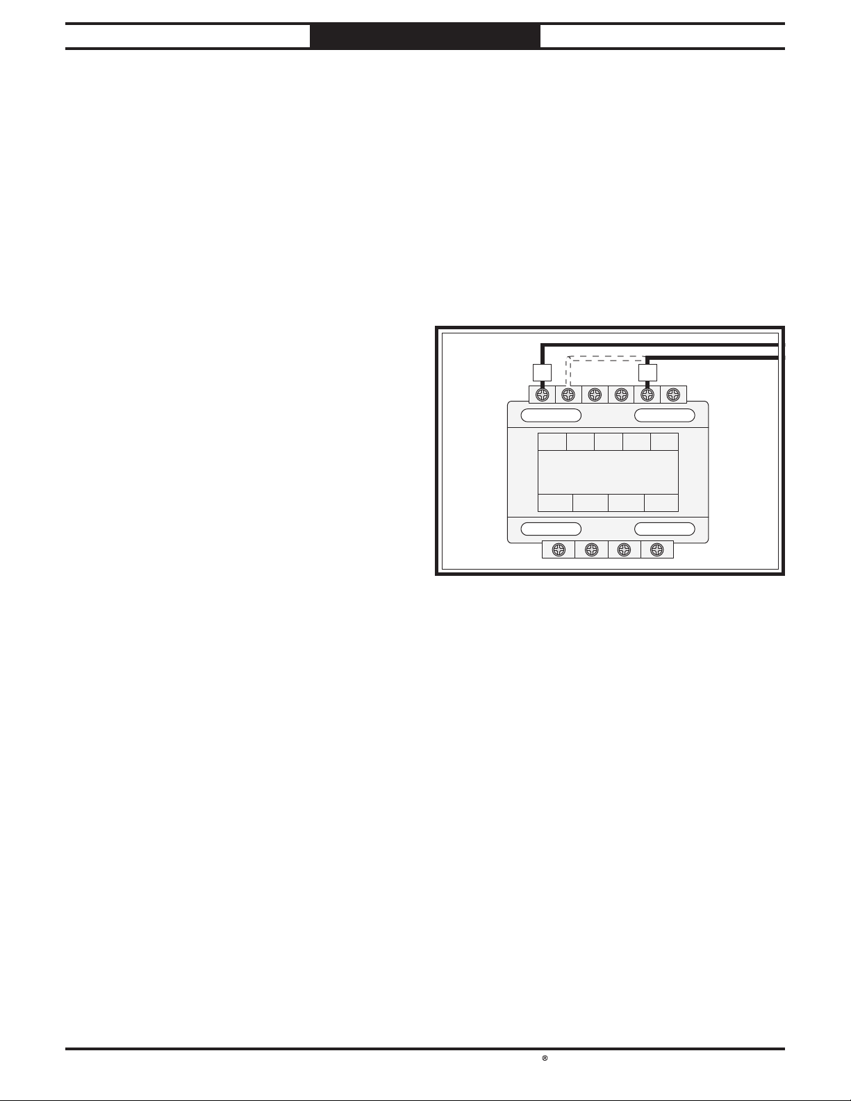
2. Open electrical cabinet and locate
transformer (see Figure 9).
3. Move "R" wire from 220V terminal to 440V
terminal (see Figure 9).
4. Remove overload relay and replace with
TECO RHU-10/4.8K1 overload relay (refer
to wiring diagrams on Pages 68–69). Set
amperage dial to 4.8A.
5. Close electrical cabinet.
6. Remove motor junction box covers on main
and coolant motors.
7. Rewire main motor and coolant pump for
440V operation (refer to wiring diagrams on
Page 71).
Note: If the diagram included on the motor
conflicts with the one in this manual, the
motor may have changed since the manual
was printed. Use the diagram provided on
the motor.
8. Install junction box covers on main and
coolant motors.
0V 220V 380V 400V 440V
110V 0V 24V 0V
Transformer
LCE
LCPIC-TBSM-100400
TR
FigureFigure 9. Moving "R" wire to 440V terminal.. Moving "R" wire to 440V terminal.
Items Needed Qty
Phillips Head Screwdriver #2...............................1
Hex Wrench 8mm .................................................1
TECO Overload Relay RHU-10/4.8K1 .................1
South Bend Tools
For Machines Mfd. Since 11/22 Model SB1124F
-17-
PREPARATION
Unpacking
This item was carefully packaged to prevent
damage during transport. If you discover any
damage, please immediately call Customer
Service at
(360) 734-1540 for advice. You may
need to file a freight claim, so save the containers
and all packing materials for possible inspection
by the carrier or its agent.
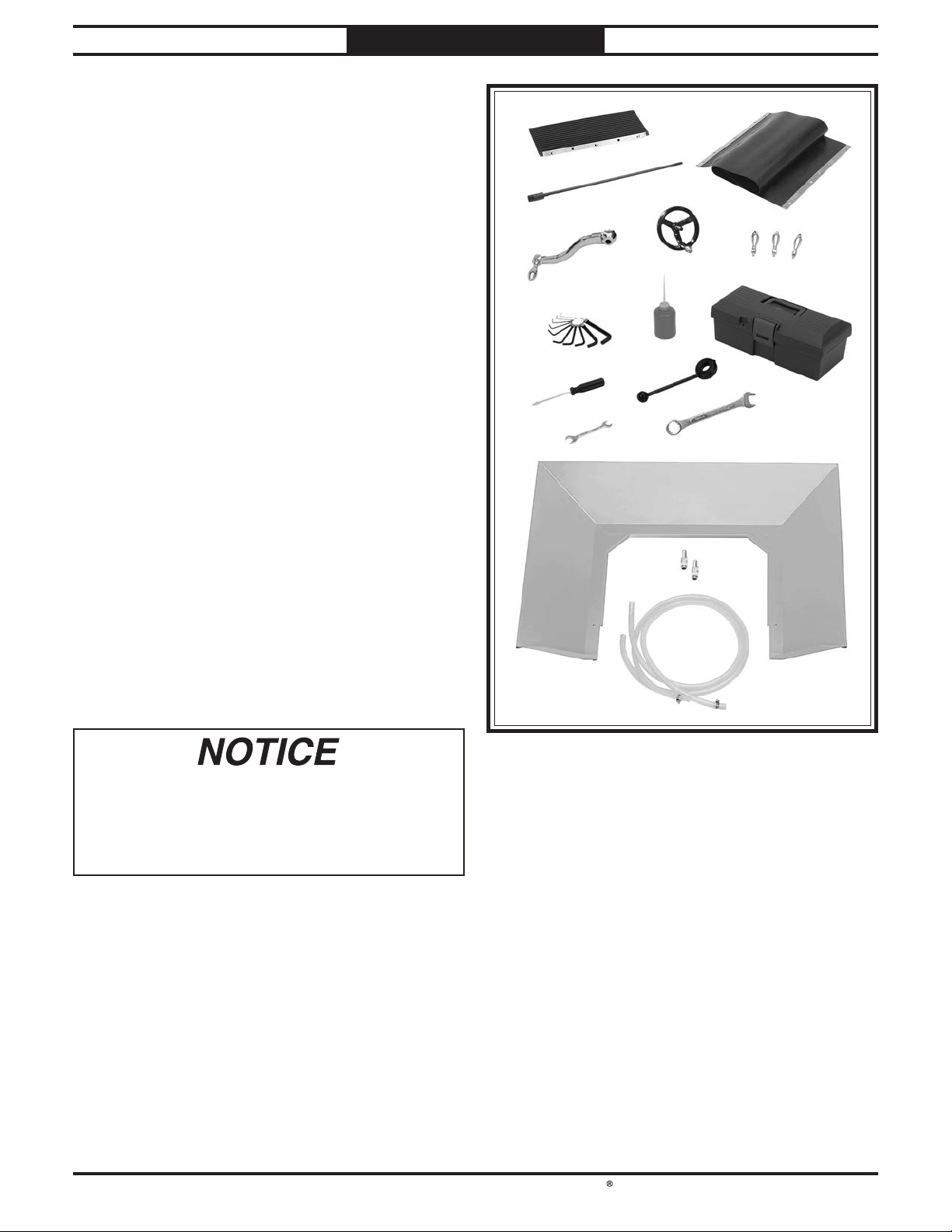
Inventory
If you cannot find an item on this list, carefully
check around/inside the machine and
packaging materials. Often, these items get
lost in packing materials while unpacking or
they are pre-installed at the factory.
Inventory (Figure 10) Qty
A. Front Way Cover............................................ 1
B. Rear Way Cover ............................................. 1
C. Drawbar 7⁄16"-20 x 18
1⁄2"..................................1
D. Knee Crank ....................................................1
E. Fine Downfeed Handwheel............................1
F. Revolving Handles .........................................3
G. Hex Wrench 10-Pc. Set 1.5–10mm................ 1
H. Oil Bottle ........................................................1
I. Tool Box ..........................................................1
J. Combination Screwdriver..............................1
K. Coarse Downfeed Lever .................................1
L. Open-End Wrench 10/12mm .........................1
M. Combo Wrench 19mm.................................... 1
N. Splash Pan......................................................1
O. Coolant Return Hose Pipe Fittings...............2
P. Coolant Return Hoses w/Clamps .................. 2
Q. Spare Key Set (Not Shown) ........................... 1
FigureFigure 10. Inventory.. Inventory.
AA
BB
CC
DD
EE
FF
GGHH
II
JJKK
LLMM
NN
OO
PP
-18-
For Machines Mfd. Since 11/22
South Bend Tools
Model SB1124F PREPARATION
The unpainted surfaces are coated
at the factory
with a heavy-duty rust preventative that
prevents corrosion during shipment and
storage.
The benefit of this rust preventative is that it
works very well. The downside is that it
can be
time-consuming
to thoroughly remove.
Be patient and do a careful job when
cleaning
and removing the rust preventative
. The time
you spend doing this will reward you with
smooth
-sliding parts and a better appreciation
for the proper care of
the unpainted surfaces.
Although there are many ways to successfully
remove the rust preventative, the
following
process works well in most situations
.
Before cleaning, gather the following:
• Disposable
rags
• Cleaner/degreaser
(certain citrus-based
degreasers work extremely well and they
have non-toxic fumes)
• Safety glasses & disposable gloves
Note:
Automotive degreasers, mineral spirits, or
WD•40 can be used to remove rust preventative.
Before using these products, though, test them
on an inconspicuous area of a painted surface to
make sure they will not damage it.
Basic steps for removing rust preventative:
1. Put on safety glasses and disposable gloves.
2. Coat all surfaces that have rust preventative
with a liberal amount of your cleaner or
degreaser and let them soak for a few
minutes.
3. Wipe off the surfaces. If your cleaner or
degreaser is effective, the rust preventative
will wipe off easily.
Note: To clean off thick coats of rust
preventative on flat surfaces, such as beds
or tables, use a PLASTIC paint scraper to
scrape off the majority of the coating before
wiping it off with your rag. (Do not use a
metal scraper or it may scratch the surface.)
4. Repeat Steps 2–3 as necessary until clean,
then coat all unpainted surfaces with a
quality metal protectant or light oil to
prevent rust.
GAS
Gasoline and petroleum
products have low flash
points and can explode
or cause fire if used for
cleaning. Avoid using these
products to remove rust
preventative.
Many cleaning solvents are
toxic if inhaled. Minimize
your risk by only using
these products in a well
ventilated area.
Avoid chlorine-based solvents, such as
acetone or brake parts cleaner that may
damage painted surfaces. Always follow the
manufacturer’s instructions when using any
type of cleaning product.
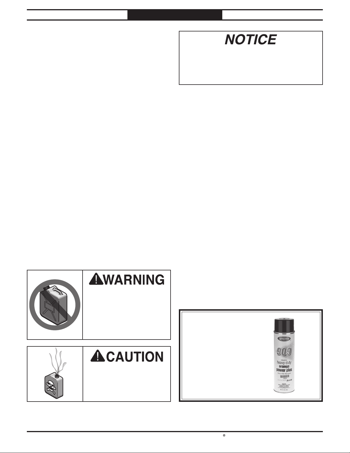
Order online at
www.grizzly.com
OR
Call 1-800-523-477
7
T23692—Orange Power Degreaser
A great product for removing the waxy shipping
grease from the non-painted parts of the
machine during clean up.
Cleaning & Protecting
FigureFigure 11.. T23692 Orange Power Degreaser.
Table of contents
Other South Bend Tools Lathe manuals

Popular Lathe manuals by other brands


Maggi
Maggi BORING SYSTEM 35 ORIGINAL USE AND MAINTENANCE MANUAL

Elem Garden Technic
Elem Garden Technic SBE2201-2L Original instructions

Roland
Roland MODELA MDX-50 user manual

Hafco Metalmaster
Hafco Metalmaster TM-1740G instruction manual

woodmizer
woodmizer Sawmill LT20 AC MH Series Safety, Setup, Operation & Maintenance Manual

Southbend
Southbend SB1307 instruction sheet


