South nt-023 User manual


MENU
1. PRECAUTIONS ..............................................................1
2. PART NAMES ................................................................ 3
3. OPERATION ..................................................................4
3.1 Keys .................................................................4
3.2 Abbreviation ....................................................5
4. ANGLE MEDASUREMENT..............................................6
4.1 Angle................................................................6
4.2 HSet .................................................................6
5. DISTANCE MEASUREMENT............................................7
5.1 Distance ........................................................... 7
5.2 Stake Out (S.O.) ................................................7
5.3 Mode ...............................................................8
6. AXES STAKE-OUT ..........................................................9
6.1 Stake Out of One Side on the Axes....................9
6.2 Stake Out of Any Point.................................... 11
7. QUICK SETTING .......................................................... 13
7.1 Laser Plummet ............................................... 13
7.2 Laser Pointer .................................................. 14
7.3 Compensation on X ........................................ 14
7.4 Distance Setting.............................................. 14
7.5 Backlight and Sound ....................................... 14
8. SETTING ..................................................................... 15
8.1 Unit................................................................ 15
8.2 Angle.............................................................. 15
8.3 Distance ......................................................... 16
8.4 PPM ............................................................... 16

8.5 Power............................................................. 16
9. CALIBRATION.............................................................. 17
9.1 Calibrate i Angle ............................................. 17
9.2 Correction of Additive Constant...................... 18
10. INFORMATION............................................................ 20
10.1 Firmware Upgrade.......................................... 20
10.2 Factory Mode................................................. 21
10.3 System Information ........................................ 21
11. SPECIFICATION ........................................................... 22
12. ERROR CODE .............................................................. 24

1
Thank you for choosing SOUTH theodolite NT-023.
Please read the user manual carefully before use.
1. PRECAUTIONS
a. Do not collimate the objective lens directly to the sunlight
without a filter.
b. Do not store the instrument in extremely high or low
temperature, to avoid the sudden or great change of
temperature.
c. When the instrument is not in use, store it in the case and
avoid shock, dust and humidity.
d. If there is great difference between the temperature in work
site and that in store place, you should leave the instrument in
the case till it adapts to the temperature of environment.
e. If the instrument has not been used for a long time, you should
remove the battery for separate storage. The battery should be
charged once a month.
f. When transporting the instrument should be placed in its
carrying case, it is recommended that cushioned material
should be used around the case for support.
g. For better accuracy, the instrument should be set up on a
wooden tripod rather than an aluminum tripod.
h. Clean exposed optical parts with degreased cotton or less
tissue only!
i. Clean the instrument surface with a woolen cloth after use. If it
gets wet, dry it immediately.
j. Before opening, inspect the power, functions and indications of
the instrument as well as its initial setting and correction

2
parameters.
k. Unless the user is a maintenance specialist, do not attempt to
disassemble the instrument by yourself even if you find the
instrument abnormal.
l. Do not aim the laser beam to eyes.
m. Keep the screen clean. Do not scratch the screen with sharp
objects.
n. This products belongs to the Level II laser products. It fully
meet the requirments of:
·IEC60825-1:2007
·GB 7247.1-2001
o. Don’t staring at the laser beam or aiming the others when
unnecessary. The laser is harmful to the eyes.
3
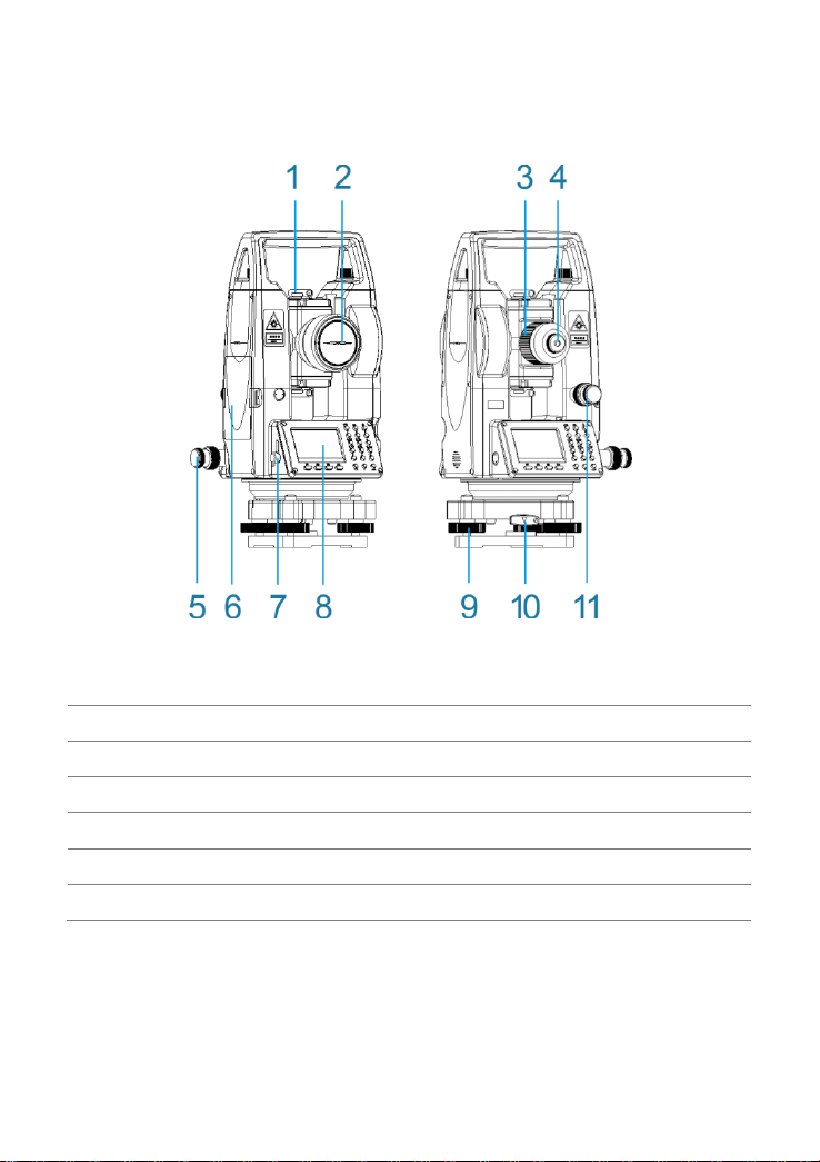
2. PART NAMES
1. Collimator
2. Objective Lens
3. Focusing Screw
4. Telescope Eyepiece
5.
Horizontal Tangent Screw
6. Battery
7. RS232 Interface
8. Display Unit
9. Tribrach
10. Tribrach Lock
11. Vertical Tangent Screw
4
3. OPERATION
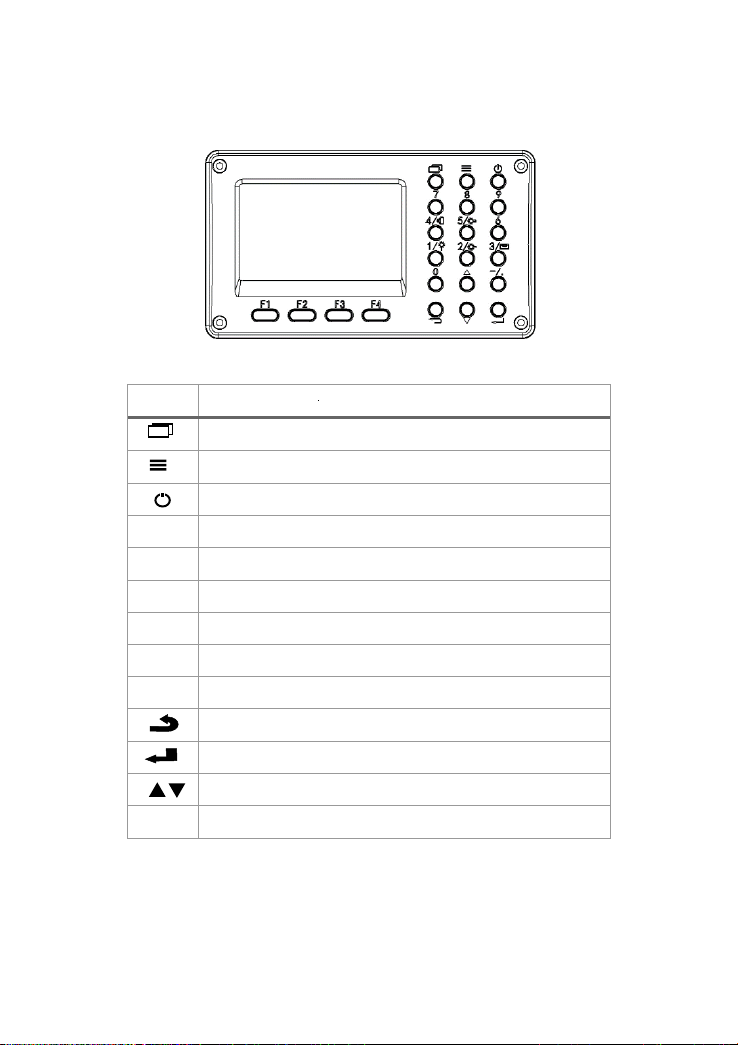
3.1 Keys
Keys
Function
Shift among 3 main functions (ANG/DIST/AXES)
Menu
Power
1
Number 1/ Shortcut to set the laser plummet
2
Number 2/ Shortcut to set the laser pointer
3
Number 3/ Shortcut to set the compensation on Axis X (N)
4
Number 4/ Shortcut to set distance measurement mode
5
Number 5/ Shortcut to set backlight and sound
6-9,0
Number 6, 7, 8, 9, 0
ESC
Enter
Move up and down/ Turn page
-/.
Input –or .

5
3.2 Abbreviation
VA
vertical angle
HA
horizontal angle
V%
degree or gradient display
HL/HR
horizontal left/right angle
VD
vertical distance
HD
horizontal distance
SD
slope distance
hPa
unit of air pressure: hectopascal
mmHg
unit of air pressure: millimeter of mercury
inHg
unit of air pressure: inch of mercury
m
unit of distance: meter
ft
unit of distance: feet
gon
unit of angle
mil
unit of angle
°C
unit of temperature: degree Celsius
°F
unit of temperature: degree Fahrenheit
6
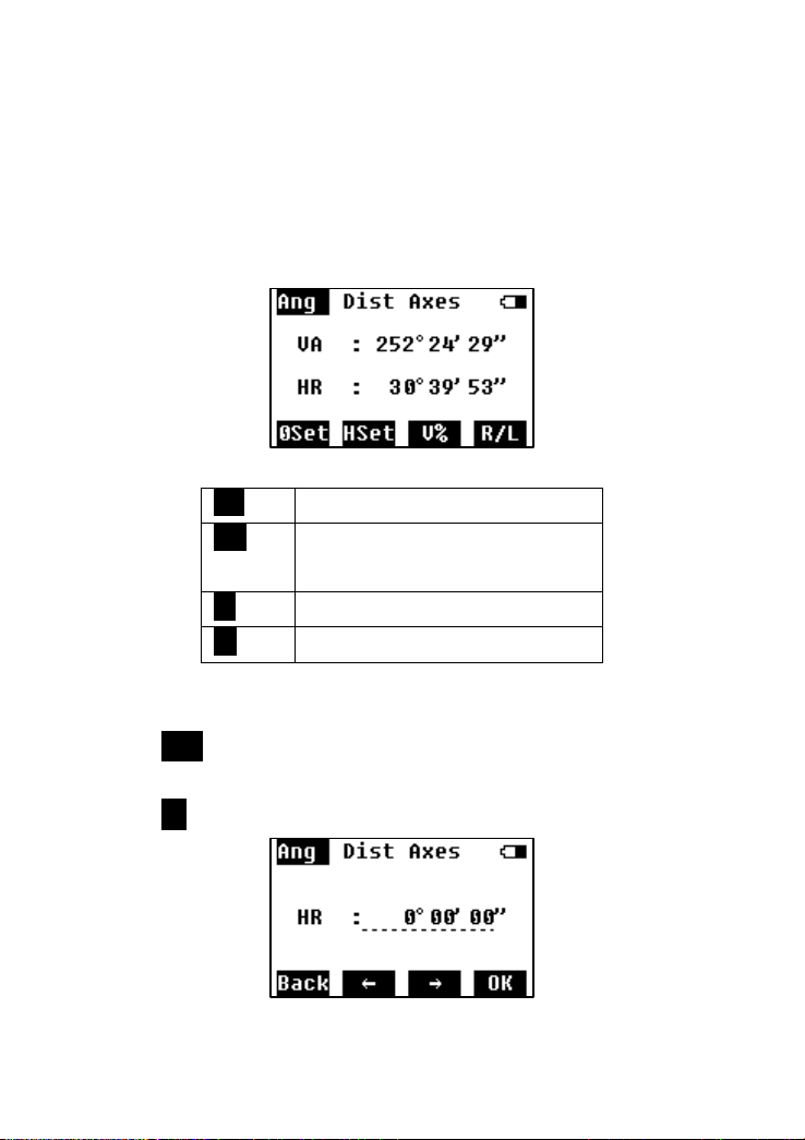
4. ANGLE MEDASUREMENT
The function of angle measurement covers measuring and displaying
vertical and horizontal angles (VA and HL/HR), 0 set, horizontal set (HSet),
switching to slope (V%), switching Face Right and Face Left (R/L), etc.
4.1 Angle
0Set:
Set the current angle to 0°.
HSet:
Input an angle to set as the current
horizontal angle.
V%:
degree or gradient display
R/L:
Shift Face Left and Face Right.
4.2 HSet
Press HSet to go the screen of setting horizontal angel.
Input a value of the angle to set as the current horizontal angle. And
press OKto confirm.
7
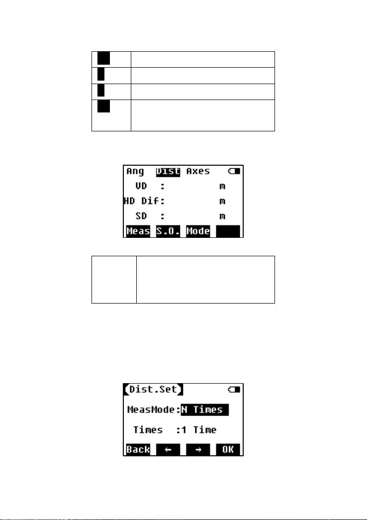
5. DISTANCE MEASUREMENT
The function of distance measurement covers measuring and displaying
vertical distance (VD), horizontal distance (HD), slope distance (SD), stake
out (S.O.), and setting of measuring mode (Mode), etc.
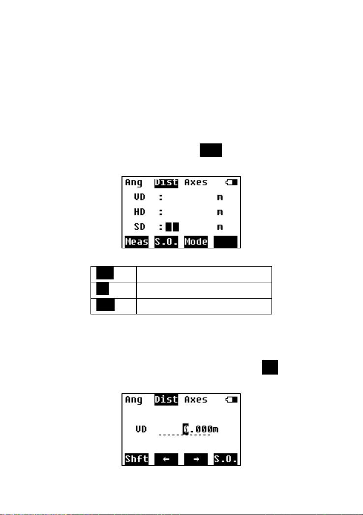
5.1 Distance
Aim at the center of the target prism through the optical eyepiece by
adjusting the focus, and press Meas to start the distance
measurement.
Meas:
Start to measure the distance.
S.O.:
Start to stake out the distance.
Mode:
Set the measure mode
5.2 Stake Out (S.O.)
Input a distance to stake out. It could be a vertical distance,
horizontal distance or slope distance, by pressing Shft to shift the
mode.
8
Shft:
shift the distance type to stake out
←:
delete
→:
move right
S.O.:
Save the input value and continue to
stake out.
Display of Stake Out Result
VD:
The distance difference between the
current horizontal distance and the
horizontal distance about to stake out.
5.3 Mode
This setting is to change the mode of measurement and measure
times.
9
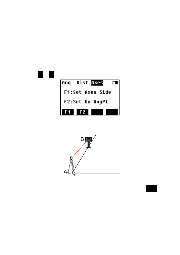
6. AXES STAKE-OUT
This session is to introduce the stake-out of the point by entering
the offset to a baseline. There’re 2 options to define the baseline.
One is to define by station point and a known bearing angle
(0°00’00”), one is to define by two new points.
Press F1 or F2 to select.
6.1 Stake Out of One Side on the Axes
Step 1: Set the theodolite at Point A.
Step 2: Aim at the prism which is set at Point B and press OSET to
set it to 0°.

10
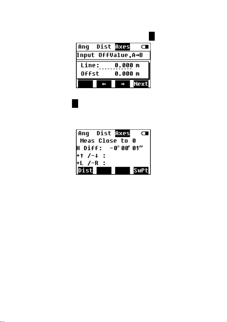
Step 3: Input the distance value of the line along Point A to B, and
the offset value.
Line
Offset value along the axes from Point
A to B.
Offst
Offset value perpendicular to the axis.
Step 4: Press F1 to measure. Move the prism according to the
indications on the screen, until all the values on the screen are 0.
H Diff
the angle difference between the HA of
Point A to staking out point and the HA
of current target

11
+↑/-↓
offset of perpendicular to the axis
+L/-R
offset along the axis
SwPt
Return to input offset to start a new
point.
6.2 Stake Out of Any Point
Stake out in this mode can set the theodolite at any point outside
the axis.
Select F2.
Step 1: Measure the distance to Point A and B, then press F4 to
next step.
12
Step 2: Input the line and offset values, press F4 to next step.
Step 3: Press F1 to measure. Indicate the poleman to move the
prism according to the indications on the screen, until all the values
on the screen are 0.

13
7. QUICK SETTING
Press Menu key and F1 Quick set to enter this page. There’re 5 settings in
QuickSet: laser plummet, laser pointer, compensation on X axes, distance
setting, backlight and sound.
7.1 Laser Plummet
Press F1 for laser plummet setting. You can also set the brightness
grade for the plummet.

14
7.2 Laser Pointer
Press F2 to turn on laser pointer.
7.3 Compensation on X axis
Turn on and off the compensation on X axis, and check the tilt
value.
7.4 Distance Setting
Set the prism constant, measure mode and measure times under
the distance setting page.
7.5 Backlight and Sound
Set the screen backlight, beep of pressing key, crosshair backlight.

15
8. SETTING
Press Menu, then F2 to enter the SET page. It covers 5 settings: unit,
angle, distance, PPM, and power set.
8.1 Unit
Set the units of angle, distance, temperature and air pressure.
8.2 Angle
Set the display of vertical angle.

16
8.3 Distance
Set the scale and height for distance measurement.
Scale
Scale factor
Ht
Elevation of the station point
8.4 PPM
Set parameters related to temperature and air pressure.
8.5 Power
Set the sleep time/ off time. Check the battery capacity directly.
SlepTime
Time to enter to sleep mode if no
operation.
Off Time
Time to power off if no operation.

17
9. CALIBRATION
Press F3 Cal. Into the calibration mode. This program is to calibrate
the errors and correct additive constant.
9.1 Calibrate i Angle
i angle is also referred to the vertical index difference.
Step 1: On Face Left, collimate the crosshair center in a collimator,
and adjust the focus until it is clear. Press OK to proceed to next
step.
Step 2: Turn the theodolite to Face Right, and collimate the same
crosshair center in the collimator until it is clear. Press OK to
proceed to next step.
Step 3: The equipment will show the index difference. Press OK to
Table of contents


