Southbend SB1231 User manual

Chucks are heavy! Get assistance when
installing or removing the chuck from the
lathe. Wear heavy duty leather boots for
foot and toe protection, and keep hands and
fingers away from all pinch points. Ignoring
this warning can lead to a severe crushing
injury or finger amputation!
Specifications
•OD Clamping...... 0.69"–10.04" (17.5–255mm)
•ID Clamping.......... 3.74"–10.83" (95–275mm)
•Chuck Bore Diameter ................2.56" (65mm)
•Chuck Outer Diameter ..........11.81" (300mm)
•Maximum Speed ...........................2500 RPM*
•Mounting Type ......................... D1-8 Camlock
• Construction..................Fine-GrainCast-Iron
• ChuckWeight......................................... 80lbs
• ChuckShippingWeight......................... 85lbs
•Country of Origin ................................ Taiwan
* ThemaximumspeedlistedaboveisONLY
possiblewiththechuckjawsandthe
workpieceincompleterotationalsymmetry.
Theworkpieceweightmustbewithinthe
limitsofthelathe,andtheworkpiecemass
mustbeofequaldensitythroughoutto
preventcentrifugalimbalanceorradial
runout—evenifatailstockorothersupport
isusedforadditionalsupport.
Instruction Sheet
PHONE: (360) 734-1540 • www.southbendlathe.com
MODEL SB1231
12" 4-JAW INDEPENDENT CHUCK
Copyright © October, 2010 by South Bend Lathe Co.
WARNING: No portion of this manual may be reproduced without written approval.
#CR13310 Printed in Taiwan
Figure 1. Features.
Introduction
TheModelSB1231usesadirectmountD1-8
camlocksystemwherethecamlockstudsare
directlythreadedintotothechuckbodyinstead
of being threaded into a backing plate that
isboltedtothechuck.Withoutusingaback
platetomountthechuck,thechuckjawsare
positionedclosertotheheadstockwhichgives
alongerdistancebetweenthejawsandthe
tailstock.Anotherbenefitisthatthedistance
betweenthejawsandtheoutboardspindlenose
isreduced,soifaspidersupportisusedonthe
outboardspindle,shortgunbarrelsandother
shorterworkpiecescanbeheldatbothends.
Manufactured
with high-tech
German CNC
machinery
Fine-grain cast
iron body
Hardened steel jaws
for durability and
extreme clamping
force and grip
Independent jaw
screws for each
reversible jaw
Direct
camlock
spindle
mounting
Jaw screw
retaining pin
with lock screws

Safety
•Chuck Key Safety:Achuckkeyleftinthe
chuckcanbecomeadangerousprojectile
whenthespindleisstarted.Alwaysremove
thechuckkeyafterusingit.Developahabit
of not taking your hand off of a chuck key
unlessitisawayfromthemachine.
•Disconnect Power: Disconnectthelathe
frompowerbeforeinstallingandremoving
the chuck or doing any maintenance or
adjustments.Accidentallathestartupcan
causesevereinjuryordeath.
•Secure Clamping: Athrownworkpiece
maycausesevereinjuryorevendeath.
Whenswappingthechuckjawpositions,
keep in mind that maximum gripping
forceisattainedatfulljawandjawscrew
engagement. Ifonlyoneispartiallyengaged,
overallclampingforceisreduced.
•Speed Rates: Operating the lathe where
maximumchuckspeedisexceeded,orattoo
highofaspeedforanunbalancedworkpiece,
cancausetheworkpiecetobethrownfrom
thechuck.Alwaysusetheappropriatefeed
andspeedrates.Athrownworkpiecemay
causesevereinjuryorevendeath.
•Large Chucks: Largechucksareveryheavy
anddifficulttograsp,whichcanleadto
crushedfingersorhandsifmishandled.
Getassistancewheninstallingorremoving
largechuckstoreducethisrisk.Protectyour
handsandtheprecisiongroundwaysby
usingachuckcradleorpieceofplywoodover
thewaysofthelathewhenservicingchucks.
•Safe Clearances: Oftenchuckjawswill
protrudepastthediameterofthechuckand
cancontactacoolantnozzle,tooling,tool
post,orsaddle.Beforestartingthespindle,
makesuretheworkpieceandchuckjaws
haveadequateclearancebyrotatingthenby
handthroughitsentirerangeofmotionby
hand.
•Stopping Lathe By Hand: Stopping the
spindlebyputtingyourhandonthe
workpieceorchuckcreatesanextremerisk
ofentanglement,impact,crushing,friction,
orcuttinghazards.Neverattempttoslow
orstopthelathechuckbyusingyourhand.
Allowthespindletocometoastoponits
ownorusethebrake(ifequipped).
•Long Stock Safety: Longstockcanwhip
violentlyifnotproperlysupported,causing
seriousimpactinjuryanddamagetothe
lathe.Reducethisriskbysupportingany
stockthatextendsfromthechuck/headstock
morethanthreetimesitsowndiameter.
Alwaysturnlongstockatslowspeeds.
-2-
Mfg.Since5/10
Model SB1231 INSTRUCTIONS
Camlock Stud Installation
Thecamlockstudsthatareshippedwiththis
chuckmaybepre-installedfromthefactory.
IfsoskipthissectionandcompleteChuck
Installation and Removal on Page 4;
otherwise,installthecamlockstudsasoutlined
below:
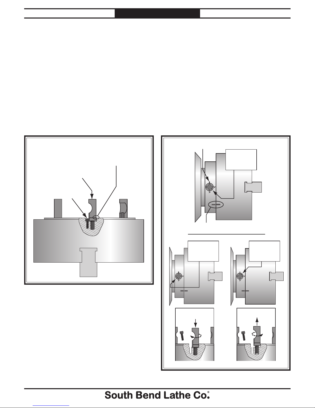
1. Oilandthreadeachcamstudintothechuck
untilthealignmentgrooveisushwiththe
chucksurface,asshowninFigure 2.
2. Installandtightenthelockingcapscrew
foreachstud,makingsurethatthecamlock
studscanslightlyrotatebackandforth.
Figure 2. Camlock stud installation.
Figure 3. Camlock stud adjustment.
Camlock Stud Adjustment
Ifthecamlockstudshavebeenpre-installedat
thefactory,orifyouareinstallingthemforthe
rsttime,slightmachiningdifferencesbetween
thelathespindleandchuckcancauseoneor
morecamlockstolockattheincorrectlocation.
If any cam line stopsoutsideofa “V” mark when
allofthecamlockshavebeentightened, remove
thechuckandadjusttheheightoftheoffending
stud one full turn up or down asillustrated
below.Afterallcamlocksoperatecorrectly,
stampalignmentmarksinthechuckandspindle
toensurethatthechuckcanbere-installedin
thesamepositionafterbeingremoved.
Camlock Stud
Must Slightly
Rotate Back/Forth
Cap Screw
Installed & Tight
Initial Adjustment:
Camlock Stud Alignment
Groove is Flush with Chuck
Surface
Alignment Marks
Spindle Line
CORRECT
The Camlock Mark
Stops Between the
“V” Marks.
To Correct:
Turn Stud One Turn In
To Correct:
Turn Stud One Turn Out
INCORRECT
The Camlock Mark
Stops Before the
“V” Marks.
INCORRECT
The Camlock Mark
Stops After the
“V” Marks.
Mfg.Since5/10 Model SB1231
-3-
INSTRUCTIONS

6. Withthehelpofanotherperson,orwiththe
helpofachuckcradle,alignthechuckwith
thespindlesothestudsandcamlockbores
arealignedcorrectly,andcarefullyslidethe
chuckontothelathespindle.Neverrestthe
chuckonitslowerstuds,asshowninFigure
5,androllorpushthetopofthechuckinto
placeonthespindle.Thisisabadpractice
thatmaydamagethestudsandcamlock
bores.
Do not install the chuck without having
the camlock cap screws in place or fully
tightened. Otherwise, the camlock studs may
turn with the camlocks on release, resulting in
the chuck being permanently locked onto the
spindle.
Figure 5. Typical alignment of studs and camlock
bores.
3. Cleanawaydebrisandoilysubstancesfrom
thematingsurfacesofthespindleandthe
chucktoensurethebestfitpossible.
4. Inspectandmakesurethatallcamlock
studsareundamaged,clean,andlightly
oiled.
5. Makesurethatthecamlockstudretaining
capscrewsaresnug,butstillallowthestuds
toberotatedbackandforthslightlybyhand.
Thisfree-playiscriticaltoensurethatthe
camlockstightenandlockwiththestuds
completely,andwillreleasewithoutbinding.
—Ifaproblemisfoundwiththecamlock
lockingorrelease,removetheoffending
studandcleanitwithmineralspirits.
Compareitwithagoodstudforany
inconsistencies,andreplaceitifaproblem
isfound.Inspectthebore,capscrew,seat
depth,andthreadswithothersthatare
knowntobecorrect.Chaseallthreads,
andremoveanyburrsordingsintheseat.
Dryouttheborewithcompressedairand
lightly re-lubricate with a drop or two of
machine oil or way oil.
Figure 4.Wooden chuck support cradle.
Before turning the lathe
ON, make sure the chuck
key is removed! A thrown
chuck key can cause
serious injury or death to
the operator or bystanders.
1. DISCONNECTLATHEFROMPOWER!
2. Layachuckcradle(seeFigure 4) or
plywoodunderthechuckandoverthe
bedwaytoprotecttheprecisionground
surfacesfromdamageandreducetheriskof
fingersgettingpinched.
Chuck Installation and Removal
INCORRECTCORRECT
-4-
Mfg.Since5/10
Model SB1231 INSTRUCTIONS
7. Tightencamlocksinastarpatterntodraw
thechuckinevenlyandreducethechance
ofmisalignment.Makesuretotighten
camlocksinanincrementalmannerto
ensurethatonecamlockdoesnotgetfully
tightenedbeforetheothers(i.e.,snugthe
camlocksonthefirstpass,thenmoderately
tightenonthenextpass,thenfullytighten
onthethirdpass).
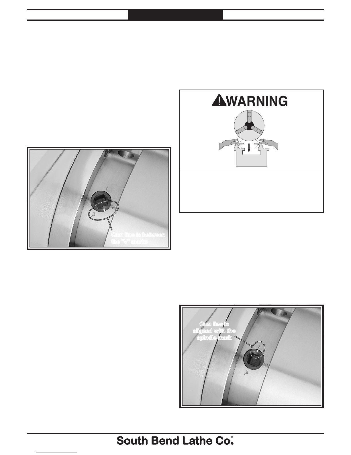
Asyoutightenthecamlocks,thechuck
willseatwiththespindlenose.Whenfully
tightened,thecamlinewillfallbetweenthe
two"V"marksonthespindlenose,asshown
in Figure 6.
Figure 6. Camlock is fully tightened with the camlock
line positioned between the "V" marks.
— Ifthecamisfullytightened,butthecam
line ispositionedoutsideofthe“V”marks,
removethechuckandadjusttheheightof
the offending camlock stud,asoutlinedin
Camlock Stud Adjustment on Page 3.
8. Wheninstallationiscompleteandyouare
satisedwiththeresults,lightlystampaset
ofalignmentmarksonthechuckandspindle.
Note: Alignmentmarksensurethatthe
chuckcanbere-installedinthecorrect
positioneverytimeforconsistentchuckand
spindlealignment.Italsoallowsforthesame
camlocksandstudstooperatetogetherfor
consistentlockingandunlocking.
Cam line is between
the "V" marks
PINCH HAZARD! Protect your hands and the
precision ground bedways with plywood or a
chuck cradle when removing the lathe chuck!
The heavy weight of a falling chuck can cause
serious injury.
To remove the chuck:
1. DISCONNECTLATHEFROMPOWER!
2. Layachuckcradleorplywoodunderthe
chuckandoverthebedwaytoprotectthe
precisiongroundsurfacesfromdamageand
reducetheriskoffingersgettingpinched.
3. Loosenthecamlocksbyturningthekey
counterclockwiseapproximatelyone-thirdof
aturnuntilthemarkonthecamlockaligns
withthespindlemarkonthespindlenose
(seeFigure 7).Ifthestuddoesnotfreely
releasefromthecamlock,wigglethecamlock
untilitstudreleases.
Note:Camlockscanbecomeverytight.Acheater
pipemaybeusedtoaddleveragewhen
loosening.
Figure 7. Camlock is fully loosened when the camlock
line is aligned with the spindle mark.
Cam line is
aligned with the
spindle mark
Mfg.Since5/10 Model SB1231
-5-
INSTRUCTIONS
CAUTION: During the next step, the
chuck may come off suddenly, so it
is important that you are ready to
support its weight with a chuck cradle
to prevent crushing your fingers or
dropping the chuck.
4. Usingadeadblowhammerorother
softmallet,lightlytaparoundtheouter
circumference of the chuck body to break the
chuckfreefromthecamlocksandthespindle
nosetaper.
5. Usearockingmotiontocarefullyremovethe
chuckfromthespindle.
—Ifthechuckdoesnotimmediatelycome
off,rotatethechuckapproximately60˚
andtapagain.Makesureallthemarks
onthecamsandspindleareinproper
alignmentforremoval.
Operation
Non-cylindricalpartscanbeheldandbrought
intothespindlecenterlineforfacingorboring
Theotherbenetisthatthemajorityof
workpiecescanbepositionedoutofthespindle
rotationaxisifabore(seeFigure 9)orastep
needstobecutintoaworkpieceonanoutlying
edge.Forthebestgrippossibleonodd-shaped
workpieces,oneormorejawscanalsoberotated
180°tograbmoresurfaceareaforclamping.
Ifallfourjawscannotbeusedtoholdthe
workpiece,youmustusefaceplatetoreducethe
riskofaworkpiecebeingthrown.
To clamp a workpiece in the chuck:
1. DISCONNECTLATHEFROMPOWER!
2. Installacenterinthetailstock.
3. Retracteachjawand place the workpiece
flatagainstthechuckface.
4. Slidethetailstockforward,sothetipofthe
deadcenterappliesenoughpressureagainst
theworkpiecetoholditinplace,andthen
lockthetailstockinposition.
5. Moveeachjawuntilitmakeslightcontact
with the workpiece.
Figure 8. Tightening sequence.
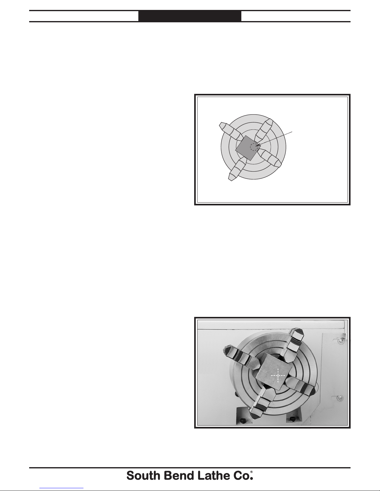
7. Aftertheworkpieceisheldinplaceby
thejaws,turnthechuckbyhandandpay
attention to the workpiece alignment.
—Iftheworkpieceisnotcorrectlyaligned
foryouroperation,turnthechuckand
makefineadjustmentsbyslightly
looseningonejawandtighteningthe
opposingjawuntiltheworkpieceis
correctlyaligned(seeFigure 9 for an
example).
1
2
3
4
Hole to be
bored into
workpiece
Figure 9. Non-concentric workpiece correctly clamped
in the 4-jaw chuck.
6. FollowingthesequenceshowninFigure 8,
tighteneachjawinsmallincrementstomove
theworkpieceintotherequiredposition.
Checkfrequentlytomakesuretheintended
centerpointoftheworkpiecehasnot
wanderedawayfromthespindlecenterline
whilethejawsarebeingtightened.
-6-
Mfg.Since5/10
Model SB1231 INSTRUCTIONS
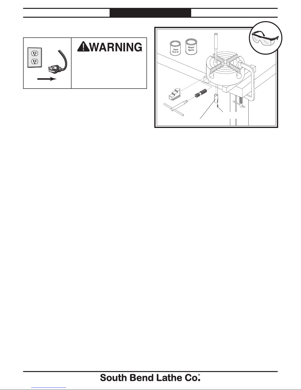
Jaw screw retaining pin
Set screw
a
Figure 10. Chuck sequence of disassembly.
Care & Maintenance
Always disconnect
machine from power before
performing maintenance or
serious personal injury may
result.
!
b. Backthejawsoutofthechuck
c. Removethefoursetscrews.
d. Putonsafetyglasses,anduseahammer
anddriftpunchtotapouteachjawscrew
retaining pin.
e. Slidethejawscrewsoutoftheirbores.
4. Usingmineralspirits,cleananddryall
parts.Inspectandxallbores,teeth,pins,
andmatingsurfacesforwear,burrs,galling,
rust,orcracks.
5. Withoutchangingthedimensionofanypart,
useawirebrush,emerycloth,ordressing
stonestoremoveallrust,burrs,oranyhigh
spotscausedbygalling.
6. CoatallpartswithanyautomotiveNLGI#2
grease,andcarefullyre-assemblethechuck
inthereverseordershowninFigure 10.
7. Rotatethechuckkeyclockwiseuntilthe
leadthreadofeachjawscrewisseenjust
enteringthejawguide,theninserteach
numberedjawintoitsnumberedslot.
8. Oneatatime,holdeachjawagainstitsjaw
screw,androtatethechuckkeyclockwiseto
engagethejawscrewwiththejaw,thenfully
threadthejawintothechuck.
9. Alignandre-installthechuck.
Foroptimumperformancefromyourchuck,
followthemaintenanceschedulebelow.Never
hammeronthechuck,jaws,oraworkpiecethat
isclampedinthechuck;andneversubjectthe
chucktoabrasives,ame,orwater.
Daily:
• Check/correctloosemountingbolts.
•Keep the chuck clean and oiled.
•Useavacuum,rag,orbrushtocleanthe
chuckafteruse. Neveruseairpressureto
cleanchipsawayfromachuck.
• Avoidleavingthechuckclampedona
workpiece,unloadthechuckjawsdaily.
• Makesurethechuckkeyisremovedfrom
thechuckwhennotinuse.
Ifthechuckeverbecomesstifftooperate,
itmayhavebeencontaminatedwithmetal
chipsorabrasivesfromincorrectorinfrequent
maintenanceintervals.Ifthisisthecase,the
chuckmustbedisassembled,cleaned,andre-
lubricated.
To disassemble the chuck for a full cleaning
and lubrication service:
1. DISCONNECTLATHEFROMPOWER!
2. Verifythatchuckalignmentmarksare
presentsothechuckcanbere-installedin
thesameposition,andremovethechuck.
Stampthemarksiftheydonotexist.
3. Leavingthecamlockstudsinplace,
disassemblethechuckinthesequencelisted
belowandshowninFigure 10.
a. Placeasetofwoodenblocksunderthe
chucksothecamlockstudsdonotreston
thetable,andclampthechucktothe
tableasshowninFigure 10.
b
c
d
e
d
Mfg.Since5/10 Model SB1231
-7-
INSTRUCTIONS
Troubleshooting
Symptom Possible Cause Possible Solution
Thechuckhas
hardspotsorbinds
completely.
1. Jawisinapoorpositionfor
clamping.
1. Re-installjawsformaximumengagementwithjaw
slotandjawscrew.
2. Lackoflubrication,rust,burr,or
metalshavingsinsideofchuck.
2. Disassemble,de-burr,clean,andlubricatechuck.
3. Brokentoothonthejaworthejaw
screw.
3. Disassemblechuckandrepair/replacebrokenpart.
Theworkpieceslips
inthejaws.
1. Incorrectjaworworkpiececlamping
position.
1. Re-installjawsformaximumengagementwithjaw
slotandjawscrew.
2. Chuckisbindingbeforefull
clampingforceisachieved,orajaw
orjawscrewisbinding.
2. Chuckisloadedupwithcontaminants.Disassemble
andservicechuck.Loosenandretightenthechuck
keyseveraltimestodistributelubricant.
3. Cuttingoverload. 3. Reduce cutting depth or feed rate.
Clamping accuracy
ispoor.
1. Workpieceimproperlyclampedor
workpieceismisaligned.
1. Removejaws,clean,de-burr,andre-install;verify
accuracyandrecalibratetest/dialindicator.
2. Chuckloose;mountingisoff-center,
orisimproperlyseated.
2. Removechuck,cleanandde-burrmounting;adjust
camlockstuds,andre-installchuck.
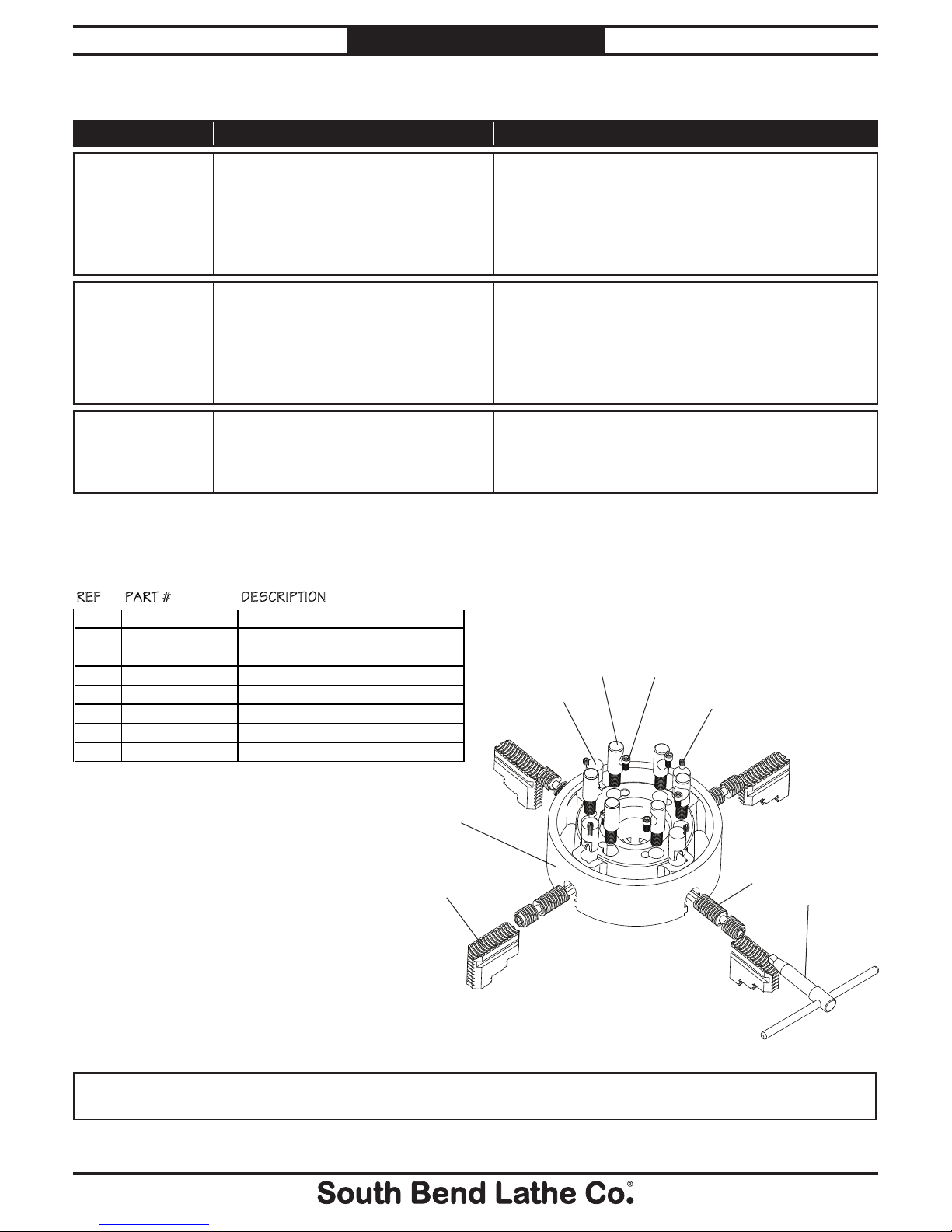
Parts List
Please Note: We included this parts breakdown for service purposes only. Since many of the parts shown are machined to
each individual chuck, they may not be available as replacement items.
Parts Diagram
REF PART # DESCRIPTION
1 PSB1231001 REVERSIBLE CHUCK JAW
2 PSB1231002 CHUCK BODY
3 PSB1231003 JAW SCREW
4 PSB1231004 JAW SCREW PIN
5 PSS02 SET SCREW 5/16-18 X 3/8
6 PSB1231006 CHUCK KEY
7 PSB1231007 D1-8 CAMLOCK STUD
8 PCAP09 CAP SCREW 5/16-18 x 5/8
6
3
2
1
5
8
7
4
If you need help with your new chuck,
contact us at:
PHONE: (360) 734-1540
FAX: (360) 676-1075 (International)
FAX: (360) 734-1639 (USA Only)
EMAIL: [email protected]
-8-
Mfg.Since5/10
Model SB1231 INSTRUCTIONS
Table of contents
Other Southbend Tools manuals


