Southern States VM-1 Service manual

Type VM-1
Motor Operator
All Ratings
INSTRUCTION
INSTALLATION &
MANUAL

The Quality Name in High Voltage Switching

The Quality Name in High Voltage Switching
Safety Information
IMPROPER HANDLING, INSTALLATION, OPERATION OR MAINTENANCE OF THIS EQUIPMENT MAY
CAUSE IMMEDIATE HAZARDS WHICH WILL LIKELY RESULT IN SERIOUS PERSONNEL INJURY OR
DEATH.
The equipment covered by this publication must be handled, installed, operated and maintained by qualified
persons who have direct knowledge and experience dealing with the hazards involved and are thoroughly
trained in the handling, installation, operation and maintenance of high voltage transmission and distribution
equipment. These instructions are meant for only such Qualified Persons. They are not intended to be a
substitute for adequate training and experience in safety procedures for this type of equipment.
A Qualified Person is one who is trained in and has skills necessary:
to read and comprehend this instruction book –understanding that these instructions are general in
nature
to accept personal responsibility to prepare and maintain an intrinsically safe work environment and
maintain control of the work site to safeguard all persons present
to develop and implement a proper rigging, lifting, and installation plan along with all safety
precautions required to insure safe and proper lifting and installation of the equipment.
to distinguish between energized and non energized parts
to determine proper approach distances to energized parts
to properly work with and around energized or de-energized equipment that may be pressurized
with gas
for proper use of personal protective equipment, insulating and shielding materials, insulated tools
for working near energized and /or pressurized electrical equipment
to recognize and take necessary precautions for the unique and dynamic conditions of site and
specialized equipment to maintain a safe work environment during handling, installation, operation,
and maintenance of high voltage switching equipment
The instructions in this manual are general guidelines for this type of equipment and not specific to the
equipment supplied. Portions of it may not be applicable or may not have complete instructions for your
specific equipment.
If you do not understand any part of these instructions or need assistance, contact Southern States Service
Division at 770-946-4562 during normal business hours (8:00am –4:30pm EST, M-F) or 770-946-4565 after
normal business hours.

The Quality Name in High Voltage Switching
LIMITED WARRANTY
Southern States, LLC (“SSLLC”) warrants only to the Warranty Holder (hereinafter defined as the “End User”
or the “Immediate Purchaser”, as applicable, pursuant to the terms and conditions of this Limited Warranty as
set forth below), that the Product identified below will, upon shipment, be free of defects in workmanship and
material for the applicable Warranty Period. The “Warranty Period” is that period of time during which this
Limited Warranty is effective, and such period begins on the invoice date issued by SSLLC for the Product,
and continues until the earlier to occur of (1) the expiration of the Warranty Duration period, or (2) the Number
of Operations, both as specified in the table below. If the Product is both purchased and installed within the
United States or Canada, this Limited Warranty is granted to each end user of the Product who acquired the
Product for its own use during the Warranty Period (“End User”). In all other situations, this Limited Warranty
is granted only to the first purchaser of the Product (“Immediate Purchaser”) from SSLLC. No primary or
remote purchaser or owner of the Product who is not a Warranty Holder may claim any benefit under this
Limited Warranty, or any remedial promise included in this Limited Warranty. SSLLC shall, upon prompt
written notice from the Warranty Holder, correct a nonconforming Product by repair or replacement at the sole
discretion of SSLLC of the nonconforming Product or any part or component of a nonconforming Product
necessary in SSLLC’s discretion to make such Product conforming. Any transportation charges, labor for
removing, reinstalling the Product or part, and/or costs related to providing access to the Product shall be the
responsibility of the Warranty Holder. Correction in this manner will constitute the Warranty Holder’s exclusive
remedy and fulfillment of all SSLLC’s liabilities and responsibilities hereunder. SSLLC’s duty to perform under
this limited warranty may be delayed, at SSLLC’s sole option, until SSLLC has been paid in full for all products
purchased by the Warranty Holder. No such delay will extend the Warranty Period. If SSLLC does not make
such repair or replacement, SSLLC’s liability for damages on account of any claimed nonconformity will in no
event exceed the purchase price of the Product in question. This Limited Warranty does not apply to any
Product that has been disassembled, repaired, or altered by anyone other than SSLLC. This LimitedWarranty
will not apply to any Product that has been subjected to improper or abnormal use of the Product. SSLLC has
no responsibility to repair or replace any Product or component thereof manufactured by another party, but
SSLLC will assign, to the extent assignable, to the Warranty Holder any manufacturers’ warranty that applies
to products and components not manufactured by SSLLC.
THIS LIMITED WARRANTY IS EXCLUSIVE AND IN LIEU OF ALL OTHER WARRANTIES. THERE
ARE NO OTHER EXPRESS, IMPLIED, OR STATUTORY WARRANTIES. ALL IMPLIED
WARRANTIES WHICH MAY ARISE BY IMPLICATION OF LAW, OR APPLICATION OF COURSE OF
DEALING OR USAGE OF TRADE, INCLUDING, BUT NOT LIMITED TO, IMPLIED WARRANTIES OF
MERCHANTABILITY OR FITNESS FOR A PARTICULAR PURPOSE, NONINFRINGEMENT OR
OTHERWISE ARE EXPRESSLY EXCLUDED. SSLLC SHALL NOT BE LIABLE OR RESPONSIBLE
FOR ANY CONSEQUENTIAL, INCIDENTAL, INDIRECT, EXEMPLARY, SPECIAL, OR PUNITIVE
DAMAGES, EVEN IF SSLLC HAS BEEN ADVISED OF THE POSSIBILITY OF SAME. THE
WARRANTY HOLDER IS SOLELY RESPONSIBLE FOR THE SUITABILITY OF THE PRODUCT FOR
ANY PARTICULAR APPLICATION.
Product Purchased
Region
Product Installed
Region
Warranty Holder
Warranty Duration
U.S and Canada
U.S and Canada
End User
Five (5) Years
All Other Conditions
Immediate
Purchaser
Earlier of 1 year from
installation or 18 months
from shipment
Revised 7/14/15

The Quality Name in High Voltage Switching
TYPE VM-1

Installation and Adjustment Procedures
3
Chapter Page
Introduction ...........................................................................................................................................................3
Important...............................................................................................................................................................3
Unpacking: ............................................................................................................................................................4
Installation:............................................................................................................................................................5
Electrical Check-Out Procedure:...........................................................................................................................7
Adjusting Switch Operation to VM-1 Rotation:......................................................................................................8
Manual Operation:.................................................................................................................................................9
Electrical Operation:..............................................................................................................................................9
Changing Output Rotation: .................................................................................................................................10
Auxiliary Switch Adjustment:...............................................................................................................................11
Reverse Motor Rotation:.....................................................................................................................................14
Swing Handle Attachment:..................................................................................................................................14
Maintenance:.......................................................................................................................................................14
Figures Page
Figure 1 - Part Identification..................................................................................................................................4
Figure 2 - Decoupler .............................................................................................................................................6
Figure 3 - Decoupler Operation ............................................................................................................................7
Figure 4 - Manual Operation.................................................................................................................................9
Figure 5 - Re-Position Locking Plate Manually...................................................................................................10
Figure 6 - Rotate with Crank Handle to Desired Position...................................................................................10
Figure 7 - Auxiliary Switch ..................................................................................................................................12
Figure 8 - CCW –LS...........................................................................................................................................13
Figure 9 - CW –LS .............................................................................................................................................13
Figure 10 - Vertical Pipe Rotates CCW to Open. ...............................................................................................13
Figure 11 - Vertical Pipe Rotates CCW to Open. ...............................................................................................13
Figure 12 - Vertical Pipe Rotates to CW To Open..............................................................................................13
Figure 13 - Vertical Pipe Rotates CW to Open...................................................................................................13
Figure 14 - Swing Handle Attachment................................................................................................................14
Important
The information contained herein is general in nature and not intended for specific application purposes. It
does not relieve the user of responsibility to use sound practices in application, installation, operation, and
maintenance of the equipment purchased. Southern States reserves the right to make changes in the
specifications shown herein or to make improvements at any time without notice or obligations. Should a
conflict arise between the general information contained in this publication and the contents of drawings or
supplementary material, or both, the latter shall take precedence.

Installation and Adjustment Procedures
4
Unpacking:
Unpack the mechanism and check for damage. If damage is found, file a claim with the carrier immediately
and notify the factory.
Figure 1 - Part Identification
Storage:
If this equipment is to be stored prior to use:
1. Store the VM-1 mechanism in the upright position
2. The door should be latched closed
3. No part of the mechanism should be submerged
4. Indoor storage or covering with a tarp is not necessary, but preferred. As with all electrical
equipment, however, condensation is a consideration.
5. The heater should be energized if the mechanism is stored outdoors for an extended period (3+
months) or in a humid environment. Refer to wiring diagram drawing for heater connection.

Installation and Adjustment Procedures
5
Static brake
The static brake is an electro-mechanical mechanism comprised of a brake pad, brake arm, spring and solenoid.
The spring provides the mechanical force necessary to depress the brake and keep the motor operator from
turning. When the motor is energized, the brake solenoid, seen in Figure 1, depresses the spring thereby
releasing the brake and allowing the motor operator to function.
Dynamic brake
The dynamic brake is a strictly electrical device. A set of contacts runs parallel to the motor which is normally
closed. When the operator needs to be stopped, a short is induced across the motor operator which therefore
stops the operator from rotating.
Installation Note: Installation consists of mounting and adjusting the VM-1 Motor Mechanism to coordinate
with the switch operating controls. Sketches and dimensions contained in this manual are for illustration only.
Refer to unit assembly drawing and operating mechanism drawing for specific dimensions.
Application Note: The VM-1 Motor Mechanism is equipped with an adjustable rotation lock that provides
variable starting and stopping points on a rotational angle between 30° and 330°. Refer to section VIII for
adjustment of this lock.
Caution: Use manual operation for installation. Do not perform electrical operation until all
adjustments are complete. Keep away from moving parts. Keep away from electrical
components unless power has been disconnected.
Installation:
1. Mount the VM-1 Mechanism as shown on the Operating Mechanism Drawing or Mounting
Arrangement Drawing. Refer to Switch Installation Instructions for switch adjustment.
2. Attach the upper decoupler member to the vertical pipe in accordance with the instructions provided
for the decoupler type supplied.
3. Universal Decoupler (Not Common)
●Do not drive in the self-piercing set screws at this time.
●The vertical pipe should bottom out in the lower decoupler section for 1-1/2 inch pipe and in the
upper decoupler section for 2 inch pipe.
●Discard cap and hardware for the unused section.
●A clearance of ½ inch must be maintained between the upper and lower decoupler members. To
adjust, raise or lower the vertical pipe in the vertical bearing at the top of the pipe. The full pipe weight
must be supported by the vertical bearing.
●When required clearance is achieved, pierce the pipe with the set screw in the pipe collar above the
vertical bearing.
●It may be necessary to pre-drill all set screw holes, using the threaded drill guides if provided.
●Refer to Figures 2 and 3 for decoupler operation. Use the decoupler key to align the upper decoupler
member with the fixed rotation lock and tighten clamping bolts. Do not pierce the pipe with set screw
at this time.

Installation and Adjustment Procedures
6
4. Single Size Decoupler:
●Do not pierce the pipe with the self-piercing set screws at this time.
●The vertical pipe should bottom out in the upper decoupler member.
●A clearance of ½ inch must be maintained between the upper and lower decoupler members. To
adjust, raise or lower the vertical pipe in the vertical bearing. The vertical bearing must support the full
weight of the pipe.
●When required clearance is achieved, pierce the pipe with the set screw in the collar above the
vertical bearing. (Do not drive set screw into coupling yet)
●If heavy wall pipe is used it will be necessary to pre-drill all set screw holes, using the threaded drill
guides when provided.
●Refer to Figure 3 for decoupler operation. Use the decoupler key to align the upper decoupler
member with the fixed rotation lock. Tighten the clamping bolts. Do not pierce the pipe until proper
switch operation has been confirmed.
Figure 2 - Decoupler
Note : If the upper decoupler member rests upon the lower decoupler member, it is not adjusted properly. The
1/2 –inch gap must be present at installation to allow thermal expansion.
Installation and Adjustment Procedures
7
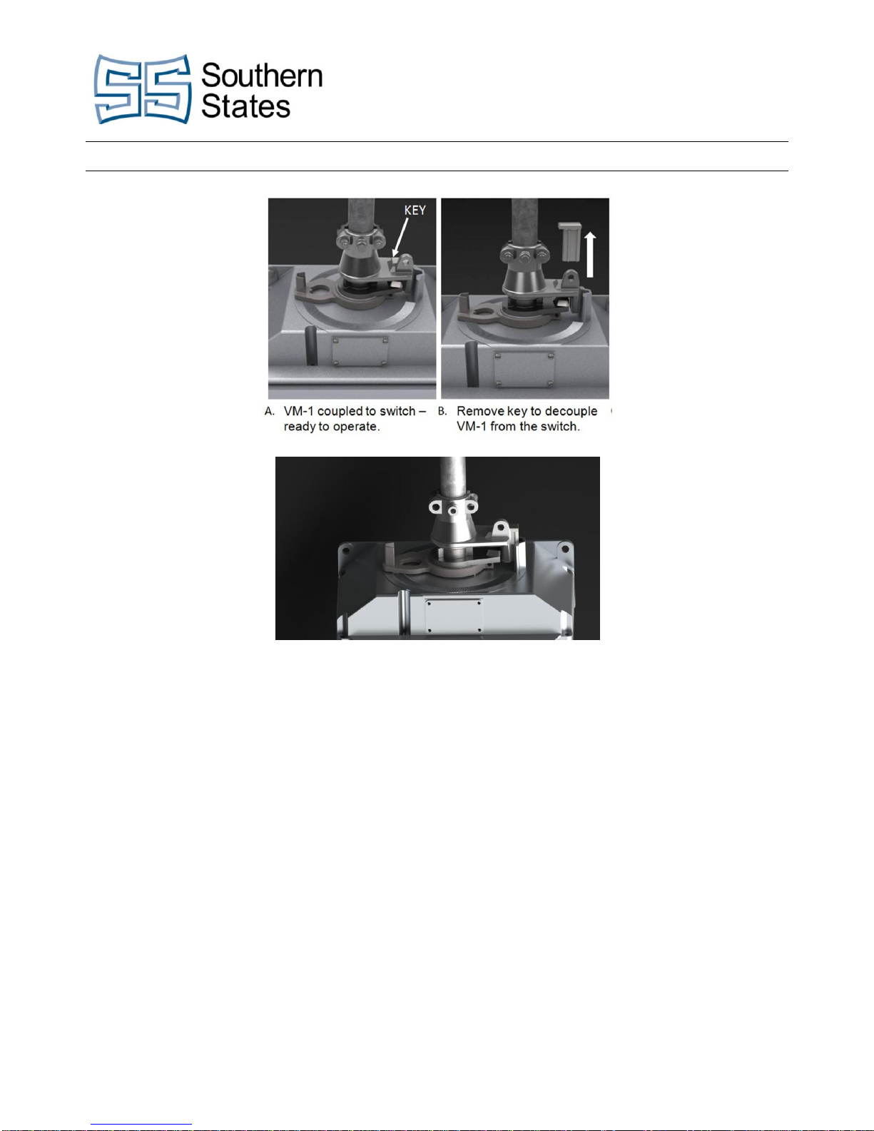
C. VM-1 Decoupled- Switch is locked out
Figure 3 - Decoupler Operation
Decoupler Operation: If decoupler key is hard to remove, use crank handle or swing
handle to back off torque load. The key should have
adequate clearance between the lower decoupler member
when the key is in the decoupled (locked out) position.
Electrical Check-Out Procedure:
1. Although electrical operation of the switch should not be attempted until later, the VM-1 mechanism
can be checked electrically now with the VM-1 decoupled from the switch
2. Decouple as shown in Figure 3 and connect the VM-1 mechanism for electrical operation as shown on
the wiring diagram drawing. Refer to Figure 1 for conduit entry into the cabinet.
3. Proper rotation is set at the factory, however adjustment may be required. Test each mechanism to
confirm rotation output agrees with the operating mechanism drawing. It is recommended the
decoupled VM-1 be hand cranked to the midpoint of rotation before the initial test operation. Use the
push buttons for testing operation.
4. OPEN and CLOSE push buttons (if supplied) initiate electrical operation.

Installation and Adjustment Procedures
8
5. STOP button (if supplied) overrides all other commands, sets the brake and halts mechanism
operation.
6. The motor fuses (or circuit breakers) must be in place for electrical operation.
7. In event of motor overload: (When Supplied)
The thermal overload relay will trip.
Remove cause of overload.
Allow motor to cool until it reaches normal operating temperature.
Reset the thermal overload relay by flipping the motor switch to the OFF position, and
then back to the ON position.
Use the OPEN and CLOSE push buttons to resume electrical operation.
8. If over or under rotation is observed, adjust the motor limit switches as directed in Auxiliary Switch
Adjustment: Page 11
Caution: Before performing any maintenance or adjustment inside the VM-1 housing, make
sure the circuits are de-energized.
Adjusting Switch Operation to VM-1 Rotation:
1. Adjust the switch operating mechanism to match the specified rotation of the VM-1 mechanism by
adapting the length of the adjustable arm at the top of the vertical pipe. Refer to the Operating
Mechanism drawing and switch installation instructions for this procedure.
2. Perform all trail operations manually. Refer to Figure 4.
3. Do not rotate the VM-1 past the open and/or close position locks. Over rotation can damage the switch
and operating mechanism.
4. The motor safety switch automatically disconnects the motor from the line voltage when the manual
crank handle is inserted.
5. Removal of the manual hand crank automatically reconnects the motor with the line voltage.
6. Refer to switch installation instructions for adjustment procedures of the operating mechanism. During
switch adjustments, use the position stops (if supplied) as reference points for fully open and fully
closed.
Installation and Adjustment Procedures
9
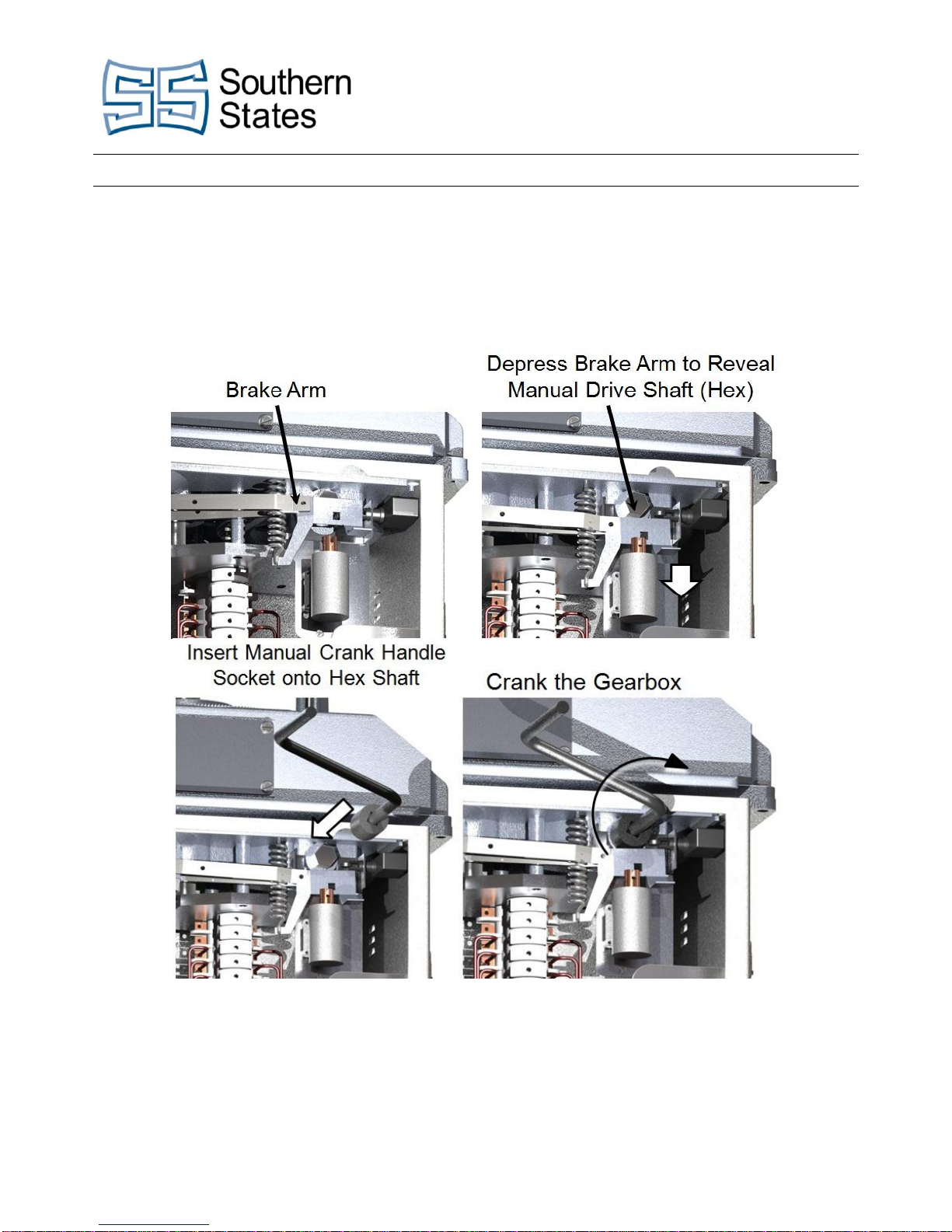
Manual Operation:
1. Depress brake arm.
2. Fit the socket on the hex head shaft.
3. Crank the gearbox manually.
Figure 4 - Manual Operation
Electrical Operation:
1. Complete adjustments of switch and operating mechanism.
2. MAKE SURE MANUAL ROTATION OF THE SWTICH MATCHES THE ELECTRICAL ROTATION OF
THE VM-1 MECHANISM.
3. Remove the manual operating handle and test electrical operation of the switch.
4. NOTE: The stop button when supplied will override all other commands.

Installation and Adjustment Procedures
10
Changing Output Rotation:
1. Two adjustments are required to change rotation of the VM-1 mechanism. The adjustable lock position
and the motor limit switch settings.
2. Loosen the adjustable lock plate and disengage-Refer to Figure 5.
3. Manually rotate the VM-1 mechanism to the desired position. (See Figure 6) Adjust the motor limit
switches to stop the motor at the new position as described in section IX. The limit switches are the
two top poles of the auxiliary switch. The motor switch and fuse switch should be in the OFF position.
4. To check degree of rotation, use cast-in rotation marks on top of the gearbox.
5. Decouple and check new rotation electrically.
6. Perform several trial operations to confirm limit switch setting is correct.
7. Rotate the adjustable lock plate to its new position and retighten.
8. If necessary, realign the pressure-sensitive open and close position indicators.
Special Application Note: To adjust the starting position, lock the upper decoupler member closed with the
clamping bolts loose and the vertical pipe free to rotate. Reposition vertical pipe to desired position. (the swing
handle socket may be used for this operation.) Tighten the clamping bolts and drive in the self-piercing set
screw after the desired starting position is achieved.
Important: The optional stop tangs(not shown) are for use as a reference point during manual operation and
are not intended to stop motor operation. Do not overdrive against these tangs.
Figure 5 - Re-Position Locking Plate
Manually
Figure 6 - Rotate with Crank Handle to
Desired Position

Installation and Adjustment Procedures
11
Auxiliary Switch Adjustment:
1. Each auxiliary switch contact is spring loaded.
2. A contact is opened and held open by a cam operating against a roller –Refer to Figure 8.
3. The Auxiliary switch is adjustable in infinite steps to open and close at any point in the line switch
operation.
4. To adjust the auxiliary switch, use a 3/32 inch Allen wrench, loosen the screw that holds the cam on
the can wheel. Do not loosen the screw more than required to allow cam movement.
5. Slide the cam around the cam wheel to desired position and retighten the screw.
6. In closed position, allow approximately ¼ inch clearance between the cam and cam roller –refer to
Figure 8
7. Retighten the cam wheel set screw firmly. Do not over tighten.
8. Perform several trial operations to make sure the setting is correct.
9. Each contact is adjusted independent of other contacts. Any contact may be made a Type A or Type B
by adjusting the switch as indicated on Figure 8, Figure 9, Figure 10, Figure 11, Figure 12 and Figure
13.

Installation and Adjustment Procedures
12
Figure 7 - Auxiliary Switch
6 mm

Installation and Adjustment Procedures
13
Procedure for Setting Auxiliary And Limit Switch Contacts
Factory Settings:
┤├ Closed in counter-clockwise limit position (CCW). (Figure 8)
┤├ Closed in clockwise limit position (CW). (Figure 9)
All Illustrations Shown From Above
Limit Switches
Figure 8 - CCW –LS
Set Mechanism (vertical pipe) in CCW limit position
and set as shown.
Figure 9 - CW –LS
Set mechanism (vertical pipe) in CW limit position
and set as shown.
Auxiliary Switches
Figure 10 - Vertical Pipe Rotates CCW to
Open.
1. Set mechanism in closed position and set
all ┤├ auxiliary switches as shown.
Figure 11 - Vertical Pipe Rotates CCW to
Open.
2. Set mechanism in open position and set all
┤├ auxiliary switches as shown.
Figure 12 - Vertical Pipe Rotates to CW
To Open.
1. Set mechanism in closed position and set
all ┤├ auxiliary switches as shown.
Figure 13 - Vertical Pipe Rotates CW to
Open.
2. Set mechanism to open position and set all
┤├ auxiliary switches as shown.

Maintenance
14
Reverse Motor Rotation:
1. Motor Mechanisms are factory wired to rotate in the direction indicated on the switch operating
mechanism drawing or customer’s order.
2. Refer to notes on the VM-1 wiring diagram should it become necessary to reverse rotation.
3. All auxiliary contacts must be readjusted after changing leads. Follow procedure described on 11.
Caution:When reversing rotation, always have the VM-1 decoupled from the switch. Leave it decoupled until
complete adjustment has been made. The motor fuses and heater fuses should be pulled during adjustment of
the auxiliary switch and overload toggle switch when provided placed in off position.
Swing Handle Attachment:
1. Attach swing handle socket as shown in Figure 14.
2. When supplied, the switch position indicator is attached to the vertical pipe, above the swing handle
socket, and aligned with indicator on the decoupler.
Note: Emergency switch operation can be performed with the Swing Handle. The Swing Handle can
also be used to provide chopping action under icing conditions or to relieve pressure when removing
the decoupler key.
Figure 14 - Swing Handle Attachment
Maintenance:
1. The VM-1 requires no maintenance under normal service conditions.
2. Should severe conditions exist:
a. Remove access plate from gear box.
b. Spray gears and shafts with a light coating of silicone lubricant every five years.
c. Apply a few drops of heavy oil (EP-type preferred) to the thrust washers supporting the center
and right-side shafts.
d. Re-seal access plate with “Permatex” (hardening grade) or equivalent.
Important: Do not use a fluid type lubricant on motor pinion due to possible seepage to the brake disc.

30 Georgia Avenue
Hampton, Georgia 30228
Phone: 770-946-4562
Fax: 770-946-8106
E-mail: support@southernstatesllc.com
http://www.southernstatesllc.com
©2015 Southern States, LLC
IB-501-VM1-Rev 1 100815 Printed U.S.A.
Table of contents
Popular Control Unit manuals by other brands


Image Engineering
Image Engineering iQ-LED V2 Setup instructions

Resol
Resol WMZ manual

Hudson Reed
Hudson Reed 1/2 NPT Instruction

WABCO
WABCO MICO ACV-DMN-LS Product Explanation, Operating Information, and Service Instructions

Bently Nevada
Bently Nevada 3500 Galvanic Isolator Interface manual

Burkert
Burkert 6213 EV operating instructions