MICO, Inc. (2) Form No. 81-463-002 Revised 2013-09-05
VALVE ADJUSTMENT
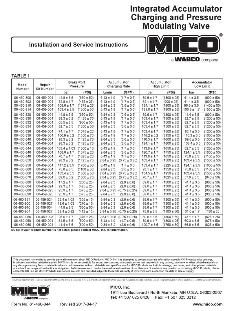
(Refer to Table 1)
1. See machine servicing instructions to properly reinstall
accumulator charging valve. Tee an accurate pressure gauge
on an accumulator line.
2. Start pump and allow approximately one minute for charging
to start (pressure in gauge will read accumulator precharge plus).
If valve does not begin to charge, stop pump and remove end
plug (25) and turn screw (24) approximately 1/4 turn clockwise.
Reinstall end plug (25). Check the high limit specications
(see TABLE 1). Repeat as needed until the high limit setting
is met. Pressure limits can be checked correctly only if afte
each adjustment of screw (24) the accumulator pressure is
reduced below the low limit setting and the system recharges
the accumulator pressure to its high limit. NOTE: Be sure to
reinstall plug (25) before starting pump.
3. Torque end plug (25) 47.5-54.2 N∙m (35-40 lb∙ft).
SERVICE INSTRUCTIONS
Disassembly
(Refer to Figure 1)
1. Remove plug (1) from housing (10). Remove o-ring (2) from
plug (1).
2. Remove spring (3), poppet (4), sleeve (6), poppet (8) and
spring (9) from housing (10). NOTE: Be careful not to
scratch or mar housing or sleeve bore.
3. Remove o-rings (5 & 7) from sleeve (6).
4. Remove plug (25) from housing (10). Remove o-ring (12)
from plug (25).
5. BEFORE moving screw (24), ACCURATELY MEASURE ITS
DEPTH from the end of housing (10) and record for reassembly
purposes. Remove screw (24) from housing (10).
6. Remove spring (22), retainer (21), and ball (20). Be sure to
keep ball (20) separate from ball (15) for reassembly.
7. Remove pin (23) from screw (24) using a drive pin punch.
NOTE: Be careful not to damage threads.
8. Remove plug (11) from housing (10). Remove o-ring (12)
from plug (11).
9. Remove spring (13), stop (14), and ball (15) from housing (10).
10. Place housing (10) on a bench with plug (11) end down.
Spool (16) may or may not fall out at this point.
11. Using a 6.4-7.9 mm (0.25-0.31 in) diameter wood or plastic
dowel, carefully remove insert (17) and spool (16) from
housing (10). Insert (17) must come out plug (11) side of
housing (10). NOTE: Be careful not to scratch or mar
valve seats on insert (17).
12. Remove spool (16) from insert (17). Remove o-rings (18 & 19)
from insert (17).
13. Remove plug (34) from housing (10). Remove o-ring (33)
from plug (34).
14. Earlier Models: Using a 1/4-20 UNC bolt, remove sleeve
(32) and orice (29) from housing (10). Remove poppet or
steel ball (28), spring (27) and stop (26) from housing (10).
Remove o-ring (31) from sleeve (32) and o-ring (30) from
orice (29). NOTE: Not all models use stop (26).
Later Models: Remove sleeve (32) from housing (10). Using
a 1/4-20 UNC bolt, remove orice (29) from housing (10).
Remove poppet or steel ball (28), spring (27), and stop (26)
from housing (10). Remove o-ring (30) from orice (29).
NOTE: Not all models use stop (26).
Assembly
(Refer to Figure 1)
WASH ALL PARTS WITH CLEAN SOLVENT AND ALLOW TO
DRY. LUBRICATE ALL RUBBER PARTS WITH CLEAN SYSTEM
FLUID PRIOR TO ASSEMBLY. BE SURE ENTIRE ASSEMBLY
PROCEDURE IS DONE WITH CONTAMINATION FREE METHODS.
1. Install new o-rings (5 & 7) on sleeve (6).
2. Install spring (9), new poppet (8), sleeve (6), new poppet (4),
and spring (3) into housing (10).
3. Install new o-ring (2) on plug (1). Install plug (1) in housing (10)
and torque 122.0-135.6 N∙m (90-100 lb∙ft).
4. Install new o-rings (18 & 19) on insert (17) and install in
housing (10). Note direction of assembly. Seat insert (17)
using a 12.7 mm (0.50 in) diameter wood dowel.
5. Install spool (16) into insert (17) in housing (10). Note direction
of spool (16), long shoulder end is toward end plug (11), see
Figure 1a.
6. Install ball (15) on insert (17) in housing (10). Install stop (14)
on ball (15).
7. Install spring (13) over stop (14).
8. Install new o-ring (12) on plug (11) and install plug (11) in
housing (10), centering spring (13). Torque plug (11)
47.5-54.2 N∙m (35-40 lb∙ft).
9. Turn housing (10) so plug (25) end is vertically upward.
Install ball (20), 6.35 mm (0.25 in) diameter. Be sure ball (20)
is centered in bottom of hole in housing (10). Install retainer
(21) and spring (22) into housing (10).
10. Insert new pin (23) in screw (24). Be sure pin (23) is aligned
properly and is evenly driven into screw (24). NOTE: Do not
damage threads.
11. Thread screw (24) into housing (10) to the depth recorded
during disassembly.
12. Install new o-ring (12) on plug (25) and install plug (25) in
housing (10). Torque plug (25) 47.5-54.2 N∙m (35-40 lb∙ft).
13. Install new o-ring (30) on orice (29).
14. Install stop (26), spring (27), new poppet or steel ball (28), and
orice (29) in housing (10). Note order and direction of parts.
NOTE: Not all models use stop (26).
15. Earlier Models: Install new o-ring (31) on sleeve (32) and
install sleeve (32) in housing (10). Note direction of sleeve
(32). Install new o-ring (33) on plug (34). Install plug (34) into
housing (10) and torque plug (34) 122.0-135.6 N∙m
(90-100 lb∙ft).
Later Models: Install sleeve (32) in housing (10). Install new
o-ring (33) on plug (34). Install plug (34) into housing (10) and
torque plug (34) 122.0-135.6 N∙m (90-100 lb∙ft).
Be sure system energy is relieved from accumulator charging
valve before removing from machine. See machine operating
instructions for procedures to relieve system energy.
NOTE
Locate the model number on the accumulator charging valve
and compare it to the model number in TABLE 1. Be sure you
you have the proper service instructions.
NOTE
Observe torque specications as indicated in assembly
procedures or system damage or failure may occur.
Do not exceed the high limit pressure setting indicated in
TABLE 1 or system damage or failure may occur.
NOTE
Items 3 through 9 are not used in single accumulator charging
valves.
NOTE
Items 3 through 9 are not used in single accumulator charging
valves.

