manuals.online logo
Brands
  1. Home
  2. •
  3. Brands
  4. •
  5. oventrop
  6. •
  7. Control Unit
  8. •
  9. oventrop Uni LH User manual

oventrop Uni LH User manual

2017 1
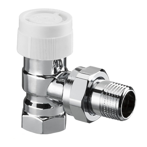
Thermostatic radiator valves
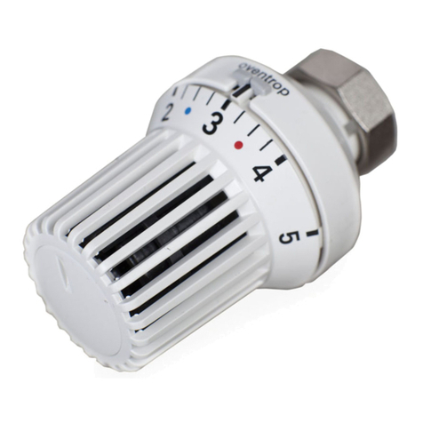
Thermostats “Uni LH” and “Uni LD”
Content:
Page 1 General information
Installation of the valve
Installation of the thermostat
Figures and symbols on the thermostat
Page 2 Limitation of the control range
Page 3 Locking of a setting
Recalibration
Cancellation of the limitation of locking
Page 4 Replacement of the gland nut
Checklist for troubleshooting
General information
Thermostatic radiator valves control the room temperature by
modifying the ow of hot water through the radiator. As the heat
demand is often very low (especially during transition periods), the
valves are opened by the thermostat to only a small amount. As
a result, ow noises may occur due to high differential pressures.
To prevent these noises, differential pressure independent
thermostatic valves, such as “AQ”, or devices inuencing the
differential pressure should be used; for example adjustable
circulation pumps, automatically working differential pressure
regulators or differential pressure relief valves.
It is recommended to adjust the ow temperature to the
outside temperature, preferably by using a weather guided ow
temperature control.
Further information can be obtained from the manual “User
instructions” and the technical data sheets “Thermostats”
and “Thermostatic radiator valves”.
Installation of the valve
The radiator valve is to be installed so that the thermostat is in a
horizontal position and a good circulation of air is guaranteed. If
this is not possible, a thermostat with remote sensor or remote
control should be used. It is most important that the capillaries
are not kinked or attened.
The radiator valve is installed in the supply pipe to the radiator,
with the ow in the direction of the arrow.
When using compression ttings, the thread of the tting and
the compression ring are slightly oiled at works. Do not use any
additional lubricant! Do not allow the oil or lubricant to come into
contact with the EPDM valve disc. EPDM is not oil resistant.
When using compression ttings for thermostatic valves with
female threaded connection (only possible for sizes DN 10,
DN15 and DN 20), the “Ox” compression ttings are to be used
to guarantee a perfect sealing function between the pipework
and the thermostatic valve.
It is important that the pipes are cut to the correct length at a right
angle to the centre line. The ends of the pipe must be free from
burrs and undamaged.
Tactile setting device
Indicator mark
Minor graduation
Direction “warmer”
Basic setting “3”, about 20 °C
Direction “colder”
Graduation gure
Tactile setting device
Handgrip
Memo disk
Collar nut “Uni LH”
or squeeze connection “Uni LD”
(0 = Complete shut off
This symbol can only be found on thermostats with ‘0’
setting)
 = Frost protection symbol,
in this position the valve opens automatically when
the room temperature drops below 7 °C.
1 = about 12 °C
2 = about 16 °C
3 = about 20 °C
4 = about 24 °C
5 = about 28 °C
Installation instructions for the specialised installer
Figures and symbols on the thermostat
When using thin walled and very soft pipes, reinforcing sleeves
have to be used. The reinforcing sleeve supports the pipe and
provides the strength to enable the necessary compression.
Reinforcing sleeves cannot be used for pipes with welded
seams. The recommendations of the pipe manufacturers have
to be observed in any case. If necessary, a practical test has to
be carried out.
The special screwed ttings “Cot S” or press ttings “Cot
P/PD/PDK” may be used for the Oventrop composition pipe
“Copipe”. The installation instructions supplied with the ttings
must be observed.
When choosing the operating uid, the latest technical status
has to be considered (e.g. VDI 2035 - Avoidance of damage to
hot water heating systems).
All radiators and pipework must be ushed thoroughly to
prevent any problems caused by welding beads and dirt.
When converting old heating systems, it is recommended that
a plastic strainer should be tted at the inlet port of all radiator
valves.
Do not t the thermostat until all building work has been
completed. During the construction period, the valve can be
operated with the protection cap. The cap is not to be used for
permanent shut-off of the valve against system pressure (e.g.
while the radiator is removed). In this case protect the valve
outlet with a metal cap.
Installation of the thermostat
To ensure an easy installation, the handgrip must be opened to
the maximum position (gure “5”). In this position, the collar nut
(“Uni LH”) or the squeeze connection (“Uni LD”) of the thermostat
may be easily tted to the valve body.
Turn the thermostat so that the indicator mark is facing up. Hold
in this position and tighten the collar nut without using excessive
force.
Pipe shape after
tightening
Reinforcing sleeve
Compression nut
Compression
ring
Compression tting before
tightening. Remove pipe
insulation far enough.
The minor graduations
between the gures 2 – 4
represent a change of the
room temperature of about
1 °C.
}
2 2017
3
5
1
Limitation of the control range
The control range of the thermostat can be limited to any upper
or lower value with the help of the clips attached to the inner side
of the handgrip. The clips can only be inserted on the inner side
of the handgrip. The two bridges of a clip have to be inserted
into two grooves of the inner framework.
Example: Limitation of the control range to a lower nominal value
of 16 °C (gure “2”) and an upper nominal value of 24 °C (gure
“4”) (e.g. for living rooms, retirement home).
Illustration 1: Remove the
handgrip with the tool (item
no. 1989100) or a pin, e.g.
with the push button of a pen.
Insert the tool/pin in the hole
provided on the lower side
of the thermostat. By turning
the handgrip to the shut-off
position, it is easily removed.
(compare illustration 16.)
Illustration 2: After having
removed the handgrip, turn
the sensor casing to the left
until the calibration mark
(bore or white stroke) is in line
with the indicator mark.
Illustration 3: On the inner
side of the handgrip you will
nd two clips in the “parking”
position. They are removed by
sliding them to the outside.
(When not in use, the clips may
of course be put back in the
“parking” position.)
4
Illustration 4 : To limit the
control range to the lower
nominal value, e.g. to gure “2”
(equals about 16 °C), one clip
is tted into the groove before
gure “2” as illustrated. (The
groove right in front of gure
“2” thus remains free.)
Illustration 5: To limit the
control range to the upper
nominal value, e.g. to gure
“4” (equals about 24 °C), the
second clip is tted into the
groove after gure “4”. (The
groove right in front of gure
“4” thus remains free.)
6
Illustration 6: Ret the
handgrip so that gure “3” is
in line with the indicator mark.
7
Illustration 7: Push down the
handgrip with the hand until it
engages. The control range of
the thermostat is now limited
and you can only set values
between gures “2” and “4”
(about 16 °C - 24 °C).
2
Indicator mark
Calibration mark
Sensor casing
Thermostatic radiator valves
Thermostats “Uni LH” and “Uni LD”
Cancellation of the limitation or locking
If the control range is limited or locked with the clips, the handgrip
cannot be removed as shown in illustration 1 or 12. In this case,
please proceed as follows:
Illustration 16 : Locked setting:
Insert the tool (item no. 1989100)
into the handgrip so that one
bridge is in the groove before
and one bridge in the groove
after the indicator mark. Push
the tool in the direction of
the arrow to loosen the clips.
Remove the tool.
Limited control range: Turn the
handgrip to the upper or lower
nominal value of the control
range.
2017 3
16
Locking of a setting
To avoid unauthorised tampering, any temperature setting
of the thermostat can be locked. Example: Locking of the
temperature setting to gure “2”. (Equals about 16 °C, e.g.
for hallways and bedrooms). To do so, remove the handgrip
as shown in illustration 1. Then turn the sensor casing until
the calibration mark (bore or white stroke) is in line with the
indicator mark as shown in illustration 2.
Illustration 8: Ret the
handgrip loosely so that
gure “3” is in line with the
indicator mark.
8
Illustration 9: Turn the handgrip
to gure “2” while pressing it
gently. Remove the handgrip.
(The calibration mark on the
sensor casing is now turned to
the right
.)
9
Illustration 10: The two clips
on the inner side of the
handgrip are to be removed
as shown in illustration 3 and
are tted into the grooves
before and after gure “2”.
(The groove right in front of
gure “2” thus remains free.)
10
Illustration 11: Ret the
handgrip so that gure “2” is
in line with the indicator mark.
The setting is now locked to
gure “2” (about 16 °C). Push
down the handgrip with the
hand until it engages.
11
Recalibration:
The thermostat is adjusted at works to 20 °C = gure “3”.
In case of misalignment, recalibration can be carried out as
follows:
12
Illustration 12: Remove the
handgrip with the tool (item
no. 1989100) or with a pin, e.g.
with the push button of a pen.
Insert the tool/pin in the hole
provided on the lower side of
the thermostat. By turning the
handgrip to the right to the
shut-off position, it is easily
removed.
13
Illustration 13: Remove the
handgrip. Turn the sensor
casing to the right until it is fully
screwed into the body of the
thermostat, then turn it to the
left again until the calibration
mark (bore or white stroke) is
in line with the indicator mark.
14
Illustration 14: If the sensor
casing is for some reason
unscrewed completely from
the body of the thermostat,
please make sure that because
of the double thread, the
correct start thread is used
when refitting the sensor
casing. After recalibration, the
distance between the body and
the sensor casing has to be
about 6 mm.
15
Illustration 15: Refit the
handgrip so that gure “3” is
in line with the indicator mark.
Push down the handgrip with
the hand until it engages.
Thermostatic radiator valves
Thermostats “Uni LH” and “Uni LD”
Insert the tool into the handgrip so that one bridge is in the groove
before and one bridge in the groove after the indicator mark. Push the
tool in the direction of the arrow to loosen the clips. Remove the tool.
The handgrip can now be removed as shown in illustration 1.
Remove the clips and reposition.
The thermostatic radiator valve does not function:
13. The thermostat is not screwed tightly onto the valve.
14. The capillary of the remote sensor or remote control was
kinked or attened. Use a new thermostat and x the
capillary carefully!
15. If a strainer is used, has it become blocked? Remove the
valve, ush the pipe thoroughly, clean the screen and
re-install the strainer.
16. Air is reducing the circulation in the radiator. Vent the
radiator.
17. Air is impairing the circulation in the heating riser. Fit an
automatic airvent at a suitable location.
18. The valve insert was damaged, for instance as a result of an
improper assembly in a vice. Fit a new valve.
19. The thermostat was misadjusted due to unauthorised
tampering. Recalibrate the thermostat (see page 3).
The valve cannot be shut off:
20. In most cases this is due to dirt particles on the valve disc,
such as welding beads or rust particles. These particles can
often be removed by repeatedly actuating the valve stem.
To do so, the thermostat must be removed rst. If the valve
disc was damaged during this operation, the valve insert
must be replaced. This can be done without draining the
system with the help of the “Demo-Bloc” tool which was
especially designed for this purpose.
If this is not successful, the valve insert must be removed
after having drained the system and the dirt particles
have to be removed from the valve or the valve has to be
replaced.
21. The frost protection responds. The crystal symbol 
corresponds to a room temperature of about 7 °C. The
valve will therefore open as soon as the temperature drops
below this level, for instance when airing the room.
22. The thermostat is defective and has to be removed. First
test whether this is due to dirt or unauthorised tampering
of the calibration. Screw on a new thermostat and return
the old one to the supplier. If still under guarantee, it will be
repaired or replaced free of charge.
The valve leaks:
23. The gland nut is loose. Tighten it.
24. The O-ring seal of the gland nut is damaged. Replace the
gland nut. The system does not have to be drained for this
purpose (see point 20).
25. The valve insert is loose. Tighten it. If necessary, use a new
insert (compare point 20).
The valve rattles:
26. Supply and return were mixed up.
Flow noises occur:
27. Can the pump head (differential pressure) be reduced?
Please contact the manufacturer in case of further questions.
4 2017
Subject to technical modications without notice.
Product range 1i
Edition 2017
Replacement of the gland nut
Remove the thermostat from the valve. Unscrew the gland nut
with a 14 mm key. Water will not escape as the valve is provided
with an additional seal. Screw on the new gland nut (item no.
1017501) and tighten with the key. Ret the thermostat.
Checklist for troubleshooting
The required room temperature is not reached or maintained:
11. The ow temperature is set too low.
12. The circulation pump is not switched on.
13. The circulation pump or the ow temperature is controlled
by a separate room thermostat.
14. The pump output is set too low.
15. The ow direction of the pump is wrong.
16. The heating pipe is throttled back or shut off.
17. With gravity fed heating systems, a circulation pump must
be installed subsequently if necessary. Gravity systems are
very sensitive to the presence of air in the system.
18. The radiator is covered by curtains, panelling etc. Use a
thermostat with remote sensor or remote control.
19. The temperature at the thermostat differs widely from the
ambient temperature due to poor siting. Use a thermostat
with remote sensor or remote control.
10. The remote sensor or remote control is badly sited. The
best height is about 1m above the oor level.
11. The radiator selected is too small for the size of the room.
12. If the required temperature is only reached at a higher
setting of the thermostat, recalibrate the thermostat (if
required).
Thermostatic radiator valves
Thermostats “Uni LH” and “Uni LD”
Note
Not for thermostatic valves “A” (since 2013), “AV 9”, “AV 6”,
“ADV9”, “ADV 6”, “CV 9”, “RF” (since 2014), “RFV 9”, “RFV 6”,
“E”, “AQ”, “RFQ” and “EQ”.
Disposal
To protect the sensor liquid from escaping, the thermostat must
not be destroyed when disposed of. The thermostat contains
hazardous waste! Dismounted/defective thermostats can be
returned to the manufacturer Oventrop. They will be disposed
of professionally.
Gland nut
SW = Spanner size

Other manuals for Uni LH

2

This manual suits for next models

1

Other oventrop Control Unit manuals

oventrop Regumat-180 Operating instructions

oventrop

oventrop Regumat-180 Operating instructions

oventrop Aquastrom DT Operating instructions

oventrop

oventrop Aquastrom DT Operating instructions

oventrop Regufloor HN User manual

oventrop

oventrop Regufloor HN User manual

oventrop Brawa-Mix Configuration guide

oventrop

oventrop Brawa-Mix Configuration guide

oventrop AV9 User manual

oventrop

oventrop AV9 User manual

oventrop Regudis W GSWB User manual

oventrop

oventrop Regudis W GSWB User manual

oventrop REGTRONIC PC Installation and operating instructions

oventrop

oventrop REGTRONIC PC Installation and operating instructions

oventrop Regufloor HX Operating instructions

oventrop

oventrop Regufloor HX Operating instructions

oventrop Oilstop V User manual

oventrop

oventrop Oilstop V User manual

oventrop Regufloor H Operating instructions

oventrop

oventrop Regufloor H Operating instructions

oventrop Multidis SFQ User manual

oventrop

oventrop Multidis SFQ User manual

oventrop Regufloor HW User manual

oventrop

oventrop Regufloor HW User manual

oventrop DynaTemp DDC CR-BX User manual

oventrop

oventrop DynaTemp DDC CR-BX User manual

oventrop AQH User manual

oventrop

oventrop AQH User manual

oventrop Multiblock TQ-RTL User manual

oventrop

oventrop Multiblock TQ-RTL User manual

oventrop Combi 4 User manual

oventrop

oventrop Combi 4 User manual

oventrop Regufloor HC Operating instructions

oventrop

oventrop Regufloor HC Operating instructions

oventrop Regufloor HW Operating instructions

oventrop

oventrop Regufloor HW Operating instructions

oventrop 168 07 06 User manual

oventrop

oventrop 168 07 06 User manual

oventrop Regudis W User manual

oventrop

oventrop Regudis W User manual

oventrop Cocon QTZ Operating instructions

oventrop

oventrop Cocon QTZ Operating instructions

oventrop Cocon QTZ User manual

oventrop

oventrop Cocon QTZ User manual

oventrop DynaTemp RBG-C F User manual

oventrop

oventrop DynaTemp RBG-C F User manual

oventrop 138119012 User manual

oventrop

oventrop 138119012 User manual

Popular Control Unit manuals by other brands

Sanhua RFGB Series instructions

Sanhua

Sanhua RFGB Series instructions

DoorHan PE200B Installation and operation manual

DoorHan

DoorHan PE200B Installation and operation manual

Parker S5A Installation, Service and Parts Information

Parker

Parker S5A Installation, Service and Parts Information

EFI fiery EB-1357 Installation and service guide

EFI

EFI fiery EB-1357 Installation and service guide

Love Controls 16A2 Series instructions

Love Controls

Love Controls 16A2 Series instructions

Burkert 6628 operating instructions

Burkert

Burkert 6628 operating instructions

Emerson IEC 62591 instruction manual

Emerson

Emerson IEC 62591 instruction manual

KSB BOAX-S manual

KSB

KSB BOAX-S manual

Honeywell BCU 460 technical information

Honeywell

Honeywell BCU 460 technical information

Nice TT3 Instructions and warnings

Nice

Nice TT3 Instructions and warnings

Siemens SIMATIC ET 200SP manual

Siemens

Siemens SIMATIC ET 200SP manual

SMC Networks VKF300 Series Installation and maintenance manual

SMC Networks

SMC Networks VKF300 Series Installation and maintenance manual

Agilent Technologies 83486A user guide

Agilent Technologies

Agilent Technologies 83486A user guide

BFT CAPRI instruction manual

BFT

BFT CAPRI instruction manual

Cameron W-K-M 370D5 Installation, operation and maintenance manual

Cameron

Cameron W-K-M 370D5 Installation, operation and maintenance manual

Dataq DI-1000TC user manual

Dataq

Dataq DI-1000TC user manual

Hardy Instruments A Series Operation and installation manual

Hardy Instruments

Hardy Instruments A Series Operation and installation manual

LOVATO ELECTRIC EXP1013 instruction manual

LOVATO ELECTRIC

LOVATO ELECTRIC EXP1013 instruction manual

manuals.online logo
manuals.online logoBrands
  • About & Mission
  • Contact us
  • Privacy Policy
  • Terms and Conditions

Copyright 2025 Manuals.Online. All Rights Reserved.