Southland H2S-625 User manual

H2S-625
Hydrogen Sulde Analyzer
Designed, Tested, and Assembled in California, USA
Rev 1.01 July 5th, 2023_BB
Instruction Manual
H2S-625 Hydrogen Sulde Analyzer
ATEX and IECEx Certied for Hazardous Areas

Part 1 Introduction
Part 2 Installation
Part 3 Operation
Part 5 Annexures
Part 4 Maintenance
1.1 General Introduction
1.2 PrincipleofOperation-TheHydrogenSuldeSensor
1.3 H2S-625Specications
1.4.1 General Safety Information (VAC)
1.4.2 General Safety Information (VDC)
1.5 Location Installation Considerations
1.6 Safety Considerations
2.1 ReceivingYourNewHydrogenSuldeAnalyzer
2.2 MountingTheHydrogenSuldeAnalyzer
2.3.1 Electrical Connections (VAC)
2.3.2 Electrical Connections (VDC)
2.3.3 EarthGroundingTheAnalyzer
2.4 Gas Connections
2.5 InstallingTheHydrogenSuldeSensor
2.6 Integral Sample System Flow Diagram
2.7 Sensor Selection
3.1 Understanding The Controls and Their Operation
3.2 Manual Range Output Adjustment
3.3 Analog Output 4 - 20mA or 1 - 5 VDC
3.4 Advanced Integral Alarms
3.5 Setting a Custom Range
3.6 Output Simulation
3.7 Output Calibration
4.1 SpanCalibrationUsingCertiedSpanGas
4.2 Procedure for Replacing the Sensor
4.3 Troubleshooting
5.1 Spare Parts List
5.2 Warranty
5.3 Material Safety Data Sheets
5.4 ConformanceCerticate
5.5 Modbus Instructions
5.6 Explosion Proof Electrical Connections
Designed, Tested, and Assembled in California, USA
Table of Contents
H2S-625 Hydrogen Sulde Analyzer

1.1 General Introduction
TheSouthlandSensingH2S-625HydrogenSuldeAnalyzerisamicroprocessorbasedonlineunitde-
signedforcontinousmeasurementsinavarietyofhazardousareaapplicationsandgasmixtures.The
AnalyzeriscertiedforuseinZone1GroupIIB+H2(ATEX,IECExandUKEX).
Theanalyzerwasdesignedwiththecustomerinmind,keepingtheoperationssimplewhilestillfeatur-
ingafastresponseandruggeddesign.Everyeorthasbeenmadetousemodernindustrialcompo-
nents and materials which has resulted in an advanced design, excellent performance, and an overall
low cost of ownership.
TheanalyzerhasnumerousoptionsincludingVACorVDCpowerinputwithanisolatedanalog4-
20mA or 1-5 VDC concentration output and optional digital RS485 Modbus RTU output meeting most
hydrogensuldeanalysisapplications.
Southland Sensing Ltd. appreciates your business and recommends reading through the complete
manualtobeabletogetthefullexperiencefromyournewhydrogensuldeanalyzer.
1.2 Principle of Operation - The Hydrogen Sulde Sensor
TheprecisionelectrochemicalhydrogensuldesensorusedintheH2S-625isdesignedandmanufac-
tured under a strict quality procedure.
Tounderstandhowthehydrogensuldeanalyzerfunctions,itisimportanttounderstandalittlebitof
the sensor characteristics.
Theactivecomponentsintheprecisionelectrochemicalhydrogensuldesensoraretheanode,cath-
ode,andaqueouselectrolytewhichareallhousedinthecellbody.Thehydrogensuldemoleculesin
the application pass through the front sensing membrane into the electrolyte, where a chemical reac-
tion occurs and a raw electrical current is generated.
TheseanalyzersneedtobecalibratedusingaspangaswithaknownH2Svalue.It’simportanttocali-
bratewiththesameowrateasyourprocessgas,werecommendaowbetween0.5-1.5SCFH.
Thiselectricalcurrentisproportionaltotheamountofhydrogensuldeintheapplication.Theanalyz-
er then processes this raw electronic signal, compensates for temperature, barometric pressure, and
owvariations,andconvertsthedataintoaparts-per-millionhydrogensuldemeasurementvalue.
Thehydrogensuldeconcentrationreadingisthendisplayedinrealtimeonthefullbacklitdisplayand
the user can automate the control of their process using any of the output signals which can be run to
Introduction
H2S-625 Hydrogen Sulde Analyzer
Designed, Tested, and Assembled in California, USA

Precision Electrochemical H2S Sensor
Designed for Natural gas & Biogas Applications
F.S. Ranges of 0 - 10 ppm up to 0 - 10000 ppm
Cost Eective and Low Maintenance
Large Backlit Display
Intuitive User Friendly Interface
Optional MODBUS RS485 RTU
2 Fully Congurable Alarm Relay Contacts
Specications:
Accuracy: < +/-1% Full Scale Range*
Alarms: 2 Congurable Relay Contacts
Analyzer Range: Multiple up to 0 - 10000 ppm
Area Classication: Zone 1 IIB + H2
Dimensions: 12” x 12”x 5.25”
Flow: 0.50 - 5.0 SCFH
Gas Connections: 1/4” Compression Tube
Output: Isolated 4 - 20mA or 1 - 5 VDC
Power: 12 - 24 VDC
100 - 240 VAC
Pressure 0.1 - 50 PSIG Inlet, vent to atm
Response Time: T90 in 45 Seconds
Sample System: Optional
Sensor: Precision Electrochemical Cell
Temperature: 0 to 50 deg C
Warranty Sensor: 12 Months
Warranty Electronics: 12 Months
Weight: 21 lbs
*Accuracy at constant conditions
Applications:
“Inquiry for Application Expertise”
• Natural Gas Extraction & Pipelines
• Natural Gas Processing
• Landll Gas Monitoring
• Biogas before and after the H2S Scrubber
• And Many Other Industrial Applications
ProductSpecicationSheet
H2S-625 H2S Analyzer
HazardousAreaOnlineProcessHydrogenSuldeAnalyzerw/SampleSystem
Designed, Tested, and Assembled in California, USA
Cross Sensitivity
Sensor response per 100 ppm of gas present:
Methyl Mercaptan: 40 ppm
Carbon Monoxide: 4 ppm
Hydrogen: 1 ppm
Sulfur Dioxide: 18 ppm
ATEX and IECEx Certied for Hazardous Areas
Optional Congurations:
- Sample System Add-On Components
- Bi-Directional RS485 Modbus RTU
- Extreme Weather Packaging
- Extended Temperature Ranges
Rev 1.09 July 5th, 2023_BB
2804

H2S-625 H2S Analyzer Product Specications
H2S Analyzer: H2S Sensor Technology:
Order Information:
Power Requirements:
H2S Sensors:
Record Part Number with selected options in Blank Indicated Area of Form
Model Number:
H2S-625H2SAnalyzer
Selected Range & Sensor:
1 0 - 200 PPM; H2S-1x PPM H2S Sensor (Ranges: 0 - 10 ppm, 0 - 50 ppm, 0 - 100 ppm, 0 - 200 ppm)
2 0 - 2000 PPM; H2S-2x PPM H2S Sensor (Ranges: 0 - 100 ppm, 0 500 ppm, 0 - 1000 ppm, 0 - 2000 ppm)
3 0 - 10000 PPM; H2S-3x PPM H2S Sensor (Ranges: 0 - 1000 ppm, 0 - 2000 ppm, 0 - 5000 ppm, 0 - 10000 ppm)
H2S-625 - - -
The H2S sensor used in the H2S-625 is based on the galvanic
electrochemical fuel cell principal. All H2S sensors are manu-
factured under a strict quality program.
The sensors are self-contained and minimal maintenance is
required - no need to clean electrodes or add electrolyte.
TheSouthlandSensingprecisionH2Ssensorsoerexcel-
lentperformance,accuracyandstabilitywhilemaximizingthe
expected life.
H2S-1x PPM H2S Sensor: 0 - 200 Max PPM Range
H2S-2x PPM H2S Sensor: 0 - 2000 Max PPM Range
H2S-3xPPMH2SSensor:0-10000MAXPPMRange
H2S sensors should be periodically calibrated. Factory recom-
mendation is every 1 - 3 months or as the application dictates.
Sensorsoerexcellentlinearitywhencalibratedtoacertied
span gas.
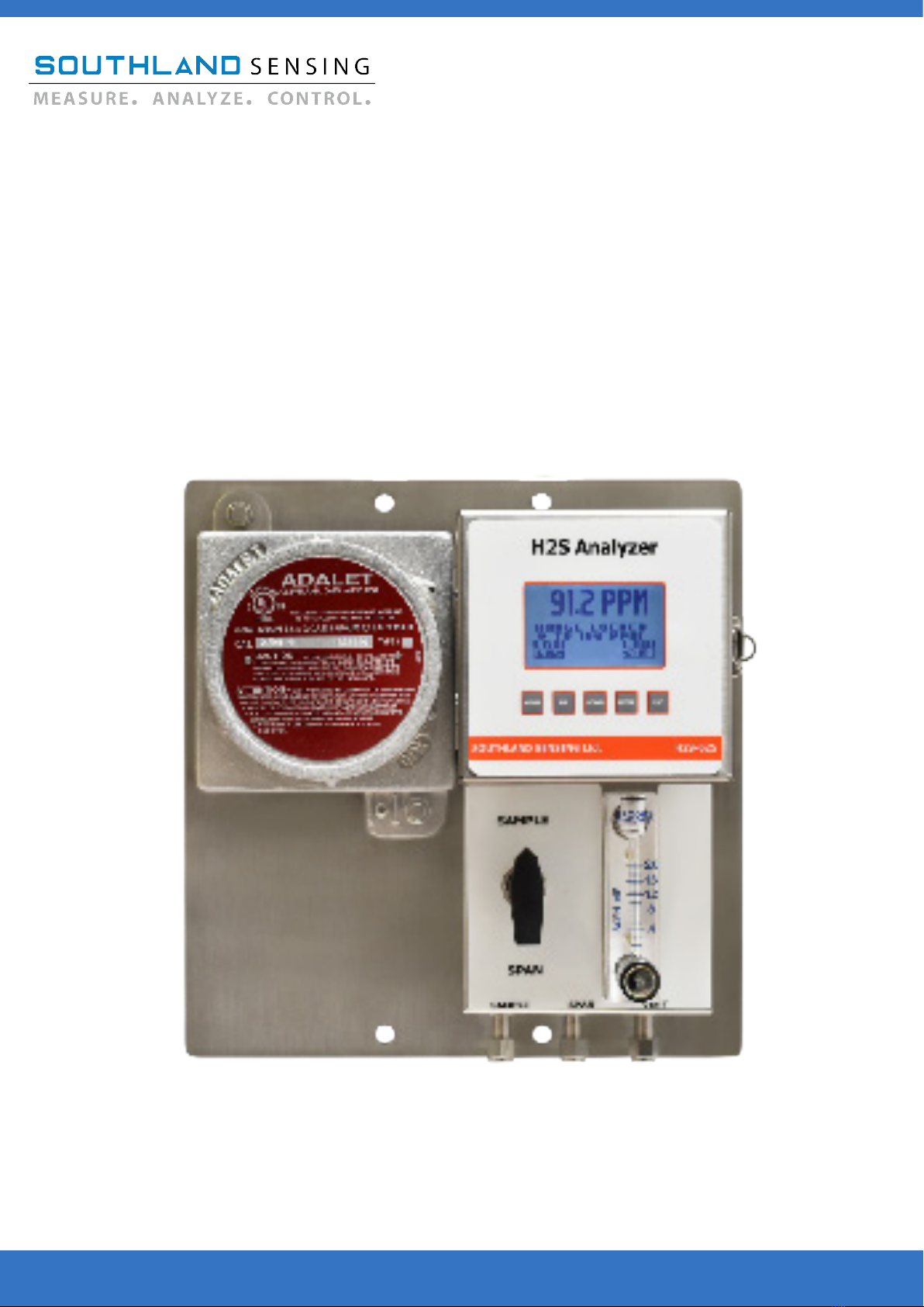
ThemodelH2S-625HydrogenSuldeanalyzer
combinesaruggeddesignwithSSO2’sprecision
H2S sensors. The result is a highly reliable and cost
eectivecompactdesignwithaneasy-to-useuser
interfacedesignedspecicallyfortheNaturalGas
and biogas industries.
TheoxygenanalyzeriscertiedforuseinZone1
IIB+H2applications.
TheH2Sanalyzerisisolatedbothonthepower
input and analog output. This eliminates most
electronic gremlins seen with existing competitive
equipmentintheeld.
Gasconnectionsaremadewith1/4”Compression
tubettings.SampleSystemsincludesSample/
Spanvalveandowmeter.
TheH2S-625analyzercomeswithanoptional
MODBUSRS485RTUBi-DirectionalCommunication
protocol.
Input Power: 12 - 24 V DC
Current Draw: 50 mA
** Optional power input choices available
Use This Part Number When Ordering
Designed, Tested, and Assembled in California, USA
Electronics Package:
4 12 - 24V DC Input Power
4M12-24VDCInputPower+MODBUSRS485RTU
7 100 - 240 VAC Input Power
7M100-240VACPower+MODBUSRS485RTU
Gas Connections:
41/4”CompressionTubeFittingswithSample/SpanValve&Flowmeter
6 6 mm CompressionTubeFittingswithSample/SpanValve&Flowmeter
DDeleteSample/SpanValve&FlowMeter,1/8”CompressionTubeFittings
Rev 1.09 July 5th, 2023_BB

H2S-625 H2S Analyzer Product Certications
Designed, Tested, and Assembled in California, USA
Rev 1.09 July 5th, 2023_BB
ATEX:
Southland Sensing Ltd.
4045 E. Guasti Rd. Suite 203, Ontario, CA 91761 USA
H2S-625 Series Hydrogen Sulde (H2S) Analyzer
ExVeritas 23ATEX1653X
II 2 G
Ex db ib IIB+H2 T4 Gb
Tamb -20⁰C to +50⁰C
IECEx:
Southland Sensing Ltd.
4045 E. Guasti Rd. Suite 203, Ontario, CA 91761 USA
H2S-625 Series Hydrogen Sulde (H2S) Analyzer
IECEx EXV 23.0038X
II 2 G
Ex db ib IIB+H2 T4 Gb
Tamb -20⁰C to +50⁰C
2804
2804

1.4.1 General Safety & Installation (VAC)
ThissectionsummarizestheprecautionsapplicabletotheH2S-625HydrogenSuldeAnalyzer.Ad-
ditionalprecautionsspecictothisanalyzerarecontainedinthefollowingsectionsofthemanual.To
operatetheanalyzersafelyandtoobtainthebestperformance,followthebasicguidelinesoutlinesin
thisowner’smanual.
CAUTION:
WARNING:
CAUTION:
Thissymbolisusedthroughouttheowner’smanualtowarnandalertthe
user of the presence of electrostatic discharge.
Thissymbolisusedthroughouttheowner’smanualtocautionandalert
theusertorecommendedsafetyand/oroperatingguidelines.
Thissymbolisusedthroughouttheowner’smanualtocautionandalert
the user that this device is operated on AC Voltage (VAC)
READ INSTRUCTIONS:Beforeoperatingthehydrogensuldeanalyzer,readtheinstructions.
RETAIN INSTRUCTIONS:Thesafetyprecautionsandoperatinginstructionsfoundintheowner’s
manual should be retained for future reference.
FOLLOW INSTRUCTIONS: Observe all precautions and operating instructions. Failure to do so may
result in personal injury or damage to the transmitter.
H2SANALYZERLABEL:
Introduction
H2S-625 Hydrogen Sulde Analyzer
Designed, Tested, and Assembled in California, USA
Model Number: H2S-625
Serial Number: 0036785
Hydrogen Sulde Analyzer
Voltage: 100 - 240 VAC
Max Current: 100mA
4045 E. Guasti Rd. #203 Ontario, CA 91761 USA
Ph: (949) 398-2879 Web: www.sso2.com
ThissectionisforACpoweredanalyzers,ifyouranalyzerisDCpoweredproceedtothenextpage.
PleaserefertoAppendix5.6formakingelectricalconnectionsthatmaintainsthedesiredlevelof
protection.

1.4.2 General Safety & Installation (VDC)
ThissectionsummarizestheprecautionsapplicabletotheH2S-625HydrogenSuldeAnalyzer.Ad-
ditionalprecautionsspecictothisanalyzerarecontainedinthefollowingsectionsofthemanual.To
operatetheanalyzersafelyandtoobtainthebestperformance,followthebasicguidelinesoutlinesin
thisowner’smanual.
CAUTION:
WARNING:
CAUTION:
Thissymbolisusedthroughouttheowner’smanualtowarnandalertthe
user of the presence of electrostatic discharge.
Thissymbolisusedthroughouttheowner’smanualtocautionandalert
theusertorecommendedsafetyand/oroperatingguidelines.
Thissymbolisusedthroughouttheowner’smanualtocautionandalert
the user that this device is operated on DC Voltage (VDC)
READ INSTRUCTIONS:Beforeoperatingthehydrogensuldeanalyzer,readtheinstructions.
RETAIN INSTRUCTIONS:Thesafetyprecautionsandoperatinginstructionsfoundintheowner’s
manual should be retained for future reference.
FOLLOW INSTRUCTIONS: Observe all precautions and operating instructions. Failure to do so may
result in personal injury or damage to the transmitter.
H2SANALYZERLABEL:
Introduction
H2S-625 Hydrogen Sulde Analyzer
Designed, Tested, and Assembled in California, USA
Model Number: H2S-625
Serial Number: 0036785
Hydrogen Sulde Analyzer
Voltage: 12 - 24 VDC
Max Current: 50mA
4045 E. Guasti Rd. #203 Ontario, CA 91761 USA
Ph: (949) 398-2879 Web: www.sso2S.com
ThissectionisforDCpoweredanalyzers,ifyouranalyzerisACpoweredseethepreviouspage.
PleaserefertoAppendix5.6formakingelectricalconnectionsthatmaintainsthedesiredlevelof
protection.

1.5 Location Installation Considerations
1.6 Safety Considerations
Thehydrogensuldeanalyzerisdesignedforinstallationintoeitherageneralpurposearea,orZone1
IIB+H2.
Theanalyzerconsistsoftwoenclosuresmountedonasinglebackpanel.ThesmallAdaletenclosure
on the left side is explosion-proof and contains the electrical connections for the user such as power,
alarms,analogoutput,anddigitalMODBUSoutput(ifapplicable).Thisexplosion-proofenclosurealso
contains the power supply and safety components for the other enclosure. The enclosure on the right
contains the analytical circuitry, the oxygen sensor, and the oxygen sensor housing. This circuitry is
designedforintrinsicsafetyandmeetsrequirementsforZone1IIB+H2.
WheninstallingaZone1IIB+H2devicepleasefollowyourlocalelectricalcodeshouldtheareaneed
tobedeclassiedpriortoinstallation.
Designed, Tested, and Assembled in California, USA
Introduction
H2S-625 Hydrogen Sulde Analyzer
TheSouthlandSensingH2S-625H2SAnalyzerisdesignedtobemountedonawalloronapipeina
generalpurposeorZone1IIB+H2area.Wheninstalledoutdoorsinextremecoldareasaheavyduty
heatedenclosureisrecommended.Consideralsogivingtheanalyzerasunshieldifitisgoingtobe
mounted in the direct sunlight.
Referenceyourlocalelectricalauthorityfortheproperinstallation.Referencesection5.6forspecic
gland requirements.
Seals/glandsarerequiredonthepowerandsignalconduletentries,referenceyourlocalelectrical
authority for the proper installation and section 5.6.
TheanalyzerisEMI/RFIprotected,howeveritisgoodpracticenottomountittooclosetosources
of electrical interference such as large transformers, motor start contactors, relays, large pumps, etc.
Alsoavoidsubjectingtheanalyzertosignicantvibration.
Mount the unit at a suitable eye level to easily read the local display. Gas connections are located on
thetoprightsideoftheanalyzer,ensurethereisadequateroomtohookupyourgaslines.

2.1 Receiving Your New Hydrogen Sulde Analyzer
Assoonasyoureceiveyournewhydrogensuldeanalyzercarefullyunpacktheunitandaccessoriesand
inspecttheinteriorandexterioroftheanalyzerfordamage,andalsoverifythehydrogensuldesensoris
present.
Ifdamagetoanyportionofthenewanalyzerispresent,stopandreportdamagetotheshippingcom-
pany as well as the factory.
Theanalyzerisshippedwithallmaterialsneededtoinstallandpreparethesystemforoperation.In
some instances, added sample system components are necessary to condition the gas sample before en-
teringthesensorhousing.SouthlandSensingoersfreeapplicationconsultationandweencourageyou
totakeadvantageofourengineersandtheirexpertise.
ItisalsoimportanttobemindfulofEMI/RFInoiseinterference.ProtectionfromEMI/RFInoiseisim-
portant for accurate readings.
Installation
H2S-625 Hydrogen Sulde Analyzer
Designed, Tested, and Assembled in California, USA

2.2 Mounting the Hydrogen Sulde Analyzer
The H2S-625 is designed to be mounted on a wall or around a pipe. See below for the mounting dimen-
sions. If mounting in extreme temperature consider an enclosure and heater if necessary.
Refer to Part 3: Operation section of this instruction manual for more information on how to operate the
controlsofthishydrogensuldeanalyzer.
RefertoPart4:Maintenancesectionforanoverviewonhowtocalibratethedeviceusingacertied
span gas.
Aprecisionelectrochemicalhydrogensuldesensorisincludedasaseparateitemandmustbeinstalled
prior to instrument use.
Designed, Tested, and Assembled in California, USA
Installation
H2S-625 Hydrogen Sulde Analyzer
H2S-625MountingDimension(Sizesareininches):

2.3.1 Electrical Connections (VAC)
Incomingpower/signaloutput
connections are made to the green
terminalblocklocatedonthe
Backoftheunit.
Donotsupplyvoltagemorethanspeciedin
thismanualandnotedontheanalyzerlabel
inside of the unit.
Shielded cable is recommended when connect-
ing power and signal output.
Voltage: 100 - 240 VAC
Max Current: 100 mA
Avoid electrostatic discharge
** Note: This device is designed to be integrated
with a PLC or DCS system. The power input should
be 100 - 240 VAC. The electronics self generate a
4 - 20mA analog output.
If optional RS485 Modbus RTU is not included J3
connectors will not be loaded.
DONOThookuppowertoeithertheANALOG
OUTPUT or RANGE ID as the circuit will be dam-
aged.
Follow your local electrical
authority for proper procedure.
It is also recommended to
makesureyouhavethepropersealsforyour
condulet to meet your required installation
consideration.Checkwithyourlocalelectrical
authority.
Designed, Tested, and Assembled in California, USA
Installation
H2S-625 Hydrogen Sulde Analyzer
ThissectionisforACpoweredanalyzers,ifyouranalyzerisDCpoweredproceedtothenextpage.
Note: For proper earth grounding, reference section 2.3.3.

2.3.2 Electrical Connections (VDC)
Incomingpower/signaloutput
connections are made to the green
terminalblocklocatedonthe
Backoftheunit.
Donotsupplyvoltagemorethanspeciedin
thismanualandnotedontheanalyzerlabel
inside of the unit.
Shielded cable is recommended when connect-
ing power and signal output.
Voltage: 10 - 24 VDC
Max Current: 100 mA
Avoid electrostatic discharge
** Note: This device is designed to be integrated
with a PLC or DCS system. The power input should
be 10 - 28 VDC. The electronics self generate a 4 -
20mA analog output.
If optional RS485 Modbus RTU is not included J3
connectors will not be loaded.
DONOThookuppowertoeithertheANALOG
OUTPUT or RANGE ID as the circuit will be dam-
aged.
Follow your local electrical
authority for proper procedure.
It is also recommended to
makesureyouhavethepropersealsforyour
condulet to meet your required installation
consideration.Checkwithyourlocalelectrical
authority.
Designed, Tested, and Assembled in California, USA
Installation
H2S-625 Hydrogen Sulde Analyzer
ThissectionisforDCpoweredanalyzers,ifyouranalyzerisACpoweredgotothepreviouspage.
Note: For proper earth grounding, reference section 2.3.3.

Designed, Tested, and Assembled in California, USA
Installation
H2S-625 Hydrogen Sulde Analyzer
2.3.3 Earth Grounding The Analyzer
Analyzer Ground Terminal Must Be Connected to Earth Ground. Conductor Size Must Be
At Least The Size Of The Power Supply Input Wire.
Analyzer Ground Terminal Must Be Ground

2.4 Gas Connections
The H2S-625 can accept either an H2S-1x (200 ppm max), H2S-2x (2000 ppm max), or H2S-3x (10,000
ppmmax)hydrogensuldesensorfortraceH2Sanalysis.Forhelpselectingasensor,contactyourlocal
sales representative or the factory.
Priortoinstallingthesensor,itisimportanttoensurethatthegaslinesarehookedupandthe
unitisreadytopurge.Connecttheprocessgaslineandsetyourowbetween0.5-1.5SCFH.
Ideally,boththespanconnectionandsampleconnectionwillhavethesameow.Werecom-
mend0.5to1.5SCFH.ItisnecessarytomatchtheowrateoftheSPANbottleandprocessgas
tomaximizeaccuracy.
To install the sensor:
- Open up the square enclosure which will give you access to the sensor housing.
- Remove the cell holder cap by unscrewing the stainless steel collar.
-Liftthestainlesssteelcollaroandsetitaside.
-Removethesensorfromitspackaging.
- Visually inspect the sensor for damage. If damaged, notify the factory immediately.
-InspecttheO-ringforcracks,replaceifnecessary.Always lubricate your O-rings.
- Place the sensor inside the housing with the white sensing element facing down and the
circuit board facing up.
- Tighten collar. Hand tight is acceptable to create an air-tight seal.
-Installtheatribboncabletothebackofthecircuitboard(seephotobelow)
-Makesurethecontactpinsontheribboncablealignwiththecontactpinsonthecircuit
board connector. The ribbon cable contact pins should be facing towards the center of
the sensor.
-Iftheanalyzerhasnotbeencalibrated,refertosection4.1formoreinformation.
-Thesensor/analyzershouldbecalibratedevery1-3monthswithacertiedbottleof
SPAN gas.
Part 2 Installation
H2S-625 Hydrogen Sulde Analyzer
Designed, Tested, and Assembled in California, USA
2.5 Installing the H2S Sensor
Gasconnectionsaremadevia1/4”compressiontubettings.Thegasconnectionsarelocatedbelowthe
sample system on the bottom right. Sample connections are designed for your process gas. Span connec-
tionsaredesignedforacertiedbottleofcalibrationgas(required).Ventistheoutlet,typicallydesigned
toventtotheatmosphere,aarestack,orperyourlocalregulations.
Ribbon Cable ConnectionH2S Sensor Front and Rear View
Rear View
(CircuitBoard)
Front View
(Sensing Surface)

2.6 Integral Sample System Flow Diagram
SouthlandSensingLtd.strivestoselectthehighestqualitysamplesystemcomponentsinthemarket.All
gasconnectionsaremadeviacompressiontubettings.Ourvalvesarehighqualityandleaktightwhich
werigorouslytestinourenvironmentalchamber.Ourowindicators/owmetersarefromDwyer,an
industryrecognizedleaderinowcontrolWhendealingwithcriticalapplicationssuchaspetrochemical
processingandnaturalgasextraction,wewanttomakesurewecandeliverahighqualitysamplesystem
andwedosobypartneringwithsomeofthebestbrandsinthemarket.
Along with our standard sample system as shown below, we can also custom design sample systems to
meetuniqueapplicationsincludingtheadditionalofmoisturelters,pressureregulators,etc.Formore
information on a custom solution for your application, please contact your local distributor or the factory.
Designed, Tested, and Assembled in California, USA
Installation
H2S-625 Hydrogen Sulde Analyzer
3-Way
Valve
Sample In
Span In
Flow
Meter
Sensor
Housing
Vent

3.1 Understanding the Controls and their Operation
TheH2S-625HydrogenSuldeAnalyzerisafeaturepackedunitwithaneasy-to-usemenuinterface.
Thekeyattributeswithinthemenuaretheabilitytoselectameasurementrangemanuallyorusing
theauto-rangemode,tocalibratetheunitwithaknowngas,alsoreferredtoasaSPANCalibration
orSPANCAL,andtoperformazerocalibration(ifnecessary,formostapplicationsitisnotrequired).
Allfeaturesareprogrammable/selectablethroughtheMENUbutton.TheUP/DOWNbuttonswill
allow you to select your set points and the ENTER button saves the data. If you want to cancel your
selection,orreturntothepreviousscreentheescapekeyESCwillallowyoutodothis.Oncetheunit
starts up, the following home screen will appear:
Current H2S Reading
Identier,Manual
or Auto Range
Operation
H2S-625 Hydrogen Sulde Analyzer
Designed, Tested, and Assembled in California, USA
Alarm 2 Setting
Alarm 1 Setting
Alarm 1 H2S Level Alarm 2 Range
Operating Range

3.2 Measurement Range Overview
TheH2S-625hydrogensuldeanalyzerallowstheusertoeldselect4availableranges-custom
ranges can be programmed in the built-in menu, see Section 3.5. These ranges can be selected in
manualmode,meaningtheyarelockedintothatrangebytheuser,ortheycanbesettoauto-range
sotheanalyzerwilladjusttogiveyouthebestfullscaleresolution.
WhenusingtheManual-RangemodetheManualRangelocksthe4-20mAoutputtoasinglerange,
and the display will continue to operate in auto-range mode giving the user the full spectrum of
analysisranges.Othermanufactureslockthedisplayaswell-theproblemisifyouover-rangeand
thedisplayislockedyouhavenoideawhatyourhydrogensuldevalueis.TheH2S-625solvesthis
issuewithadisplaythatauto-rangesandtheabilitytomanuallylocktheanalogoutputs.
ToselectAuto-RangeorManual-RangeMode,fromtheHOMEscreen,presstheMENUkeyandthe
display will indicate:
UsingtheUP/DOWNkeystochangewhichoptionishighlighted
will allow the user to select AUTO-RANGE, which will all the unit to
cyclethroughallveranges,orMANUALRANGEwhichwillallow
theusertoselectaspecicrange.
Decidewhichoptionwillworkbestforyourapplication.
HighlighttheselectionandpresstheENTERkey.Ifyou
haveselectedtheAUTORANGEoption,itwillblinkfora
second indicating this was selected. If you selected the
MANUAL RANGE option, the following screen will be brought up:
H2S-1x: 0 - 10 ppm, 0 - 50 ppm, 0 - 100 ppm, 0 - 200 ppm
H2S-2x: 0 - 100 ppm, 0 - 500 ppm, 0 - 1000 ppm, 0 - 2000 ppm
H2S-3x: 0 - 100 ppm, 0 - 2000 ppm, 0 - 5000 ppm, 0 - 10000 ppm
If a custom range has been set, it will appear below the lowest range.
UsetheUP/DOWNkeystohighlighttherangetobeselectedandpress
theENTERkey.Theselectedrangewillblinkforasecondindicatingtherangehasbeenselected.
PresstheESCkeytomovebacktothepreviousscreen.
Designed, Tested, and Assembled in California, USA
Operation
H2S-625 Hydrogen Sulde Analyzer
MANUAL RANGE
0 - 200 PPM
0 - 100 PPM
0 - 50 PPM
0 - 10 PPM
MAIN MENU
AUTO RANGE
MANUAL RANGE
SPAN CAL
ZEROCAL
ALARM 1
ALARM 2
SYSTEM

3.3 Analog Output
** Caution: Integral 4 - 20mA converters are internally powered and do not re-
quire external power. DO NOT supply any voltage across these terminals as the
4 - 20mA output will be damaged. It is also important to assure proper ground-
ing of the external recording device such as a PLC, DCS prior to connecting the 4
- 20mA.
The H2S-625 is equipped with a 4 - 20mA analog output. When physically connecting the analog
output, refer to the circuit board pinout in section 2.3
Toverifythesignaloutputofthe4-20mAcircuitisworkingproperly,connectanammeteracrossthe
(+)and(-)pins.Withnohydrogensuldesensorconnected,itshouldreadapproximately4mA.Ifa
sensor is installed you can verify the signal matches with the following formula:
SignalOutput(mA)=[(Reading/FullScaleRange)x16]+4
For example, if we are reading 500ppm on the 1000 ppm range:
SignalOutput(mA)=[(500/1000)x16]+4
Signal Output (mA) = 12mA
SomePLC’sprefera1-5VDCanalogoutput.Theoutputcanbeconguredforeither4-20mAor
1-5 VDC using the built-in menu. Enter the MENU and select SYSTEM, select OUTPUT TYPE and it will
allow you to select either analog output (4 - 20mA or 1 - 5V DC).
Designed, Tested, and Assembled in California, USA
Operation
H2S-625 Hydrogen Sulde Analyzer

TheH2S-625HydrogenSuldeAnalyzerisequipedwith2advancedrelaycontactalarms.These
alarmscanbeconguredasnormallyopenornormallyclosed,haveadelaymodebuilt-in,andcan
be enabled or disabled when necessary.
The alarms are rated at 5A @ 230VAC. If you are connecting to solenoid valves or a pump whose
currentcanuctuategreatly,itisadviseabletouseaslaverelaytoensurenodamageoccurstothe
electronics.
The procedure for setting Alarm 1 and Alarm 2 is identical. To begin,
highlightthealarmcongurationyouwanttoadjustusing
theUP/DOWNkeysintheanalyzerMENUandpressENTER.
To adjust the value setpoint of ALARM 1 simply highlight ALARM 1
and press ENTER. Select the ADJUST ALARM option, where you
willbeabletoadjustthelevelsusingtheUP/DOWNbuttons.Toset
a PPM level alarm simply hold the DOWN button until you get below
1%. To set the alarm press ENTER.
The alarm function allows the user to set the alarm to trigger the relay
contacts as a HIGH alarm or a LOW alarm. Simply
open the ALARM 1 menu and UP or DOWN to meet your
requirements.
The alarm has a built in DELAY TIME. This is ideal to use when you
areworkingonyourprocessanddonotwanttohavethealarmrelay
contacts trip. You will set this in a similar fashion to setting the alarm.
The DELAY TIME is in minutes, so adjust the value accordingly.
Thealarmcanalsobeenabled/disabledshoulditbehookedupbut
notrequired.HighlightALARMON/OFFusingtheUP/Downkeysto
andpresstheENTERkey.
The alarms can function as normally open or normally closed. This
selectionwillbechoosenwhenhookingupthewiring,itisnot
completed through the software. See the wiring diagram in section 2.4
for more information.
If you any questions about the ALARM functions should arise, please
contact the factory for assistance or technical questions.
3.4 Advanced Integral Alarms
Operation
H2S-625 Hydrogen Sulde Analyzer
Designed, Tested, and Assembled in California, USA
ALARM 1 MENU
ALARMON/OFF
ALARM TYPE
ADJUST ALARM
DELAY MODE
MAIN MENU
AUTO RANGE
MANUAL RANGE
SPAN CAL
ZEROCAL
ALARM 1
ALARM 2
SYSTEM
Table of contents
Popular Measuring Instrument manuals by other brands

Flow-Rite
Flow-Rite Eagle Eye Essential IV Installation & operation instructions

Kusam-meco
Kusam-meco KM 072 quick start guide

Acuity
Acuity AS2100 manual

ND
ND MultiCube Single Phase Installation and operation

Kistler
Kistler 9287C Series instruction manual

Kobold
Kobold Heinrichs BGN Series Installation and operating instructions

yellow jacket
yellow jacket YJACK Series quick start guide

CS Instruments
CS Instruments 0554 0504 Operation manual

Shinko
Shinko DFT-700-M instruction manual

Servomex
Servomex SERVOTOUGH SpectraExact 2500 Series installation manual

Armstrong
Armstrong Steam QM-3 Installation and operation manual

TR-Electronic
TR-Electronic LE-200 user manual