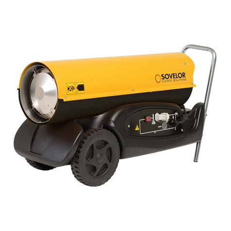
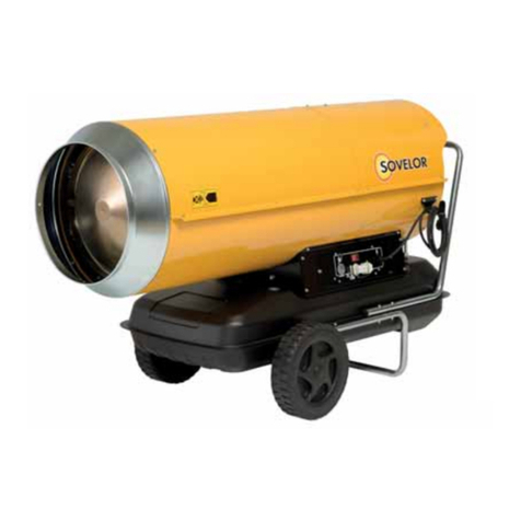
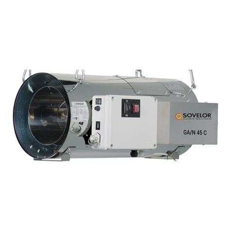
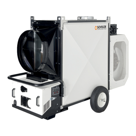
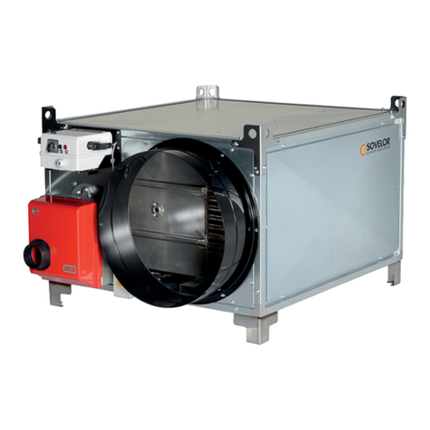
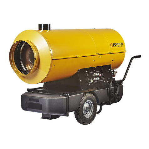
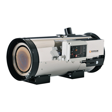
Sovelor MASTER CED2 Manual

MA
STER CED2
86(5$1'0$,17(1$1&(%22.
en
0$18(/'ಬ87,/,6$7,21(7'(0$,17(1$1&(
fr

CARACTERISTIQUES TECHNIQUES
B 70 CED 2 B 100 CED 2 B 150 CED 2
Puissance max.
20 kW
17500 kcal/h
70000 Btu/h
29 Kw
25000 Kcal/h
100000 Btu/h
44 Kw
38000 Kcal/h
150000Btu/h
Débit d’air
à 70°C 475 m3/h 950 m3/h 1070 m3/h
Consommation 1.7 Kg/h 2.45 Kg/h 3.72 Kg/h
Carburant Fuel ou gasoil
Capacité
réservoir 19 l 44 l 44 l
Alimentation
électrique
230V ~1 50Hz
90 W – 1 A
230V ~1 50Hz
190 W – 1.2 A
230V ~1 50Hz
190 W – 1.2 A
Tr/min 2850 2850 2850
Pression de
fonctionnement 0.36 Bar 0.27 Bar 0.34 Bar
Portable Sur roues
Dimensions
Lxlxh 760x300x410 760x420x530 1075x480x610 1075x480x610

326,7,21
48$17,7( ; ; ; ; ; ; ;
),*85(6

IMPORTANT: LIRE ET COMPRENDRE CE MANUEL D’UTILISATION AVANT
DE PROCEDER A L’ASSEMBLAGE, A LA MISE EN SERVICE OU A LA
MAINTENANCE DE CE GENERATEUR. L’UTILISATION INCORRECTE DU
GENERATEUR PEUT CAUSER DE GRAVES LESIONS. CONSERVER CE
MANUEL EN VUE DE FUTURES CONSULTATIONS.
1. INFORMATIONS SUR LA SECURITE
AVERTISSEMENTS
!IMPORTANT: Cet appareil n’est pas
adapté pour être utilisé par des personnes
(y compris les enfants) ayant des capacités
physiques, sensorielles et mentales réduites
ou par des personnes inexpérimentées, à
moins qu’elles ne soient supervisées par
une personne responsable de leur sécurité.
/HV HQIDQWV GRLYHQW rWUH VXUYHLOOpV D¿Q GH
s’assurer qu’ils ne jouent pas avec l’appa-
reil.
!DANGER: L’asphyxie par le monoxyde
de carbone peut être fatale.
Les premiers symptômes de l’asphyxie par
le monoxyde de carbone ressemblent à ceux
de la grippe, avec des maux de tête, des
vertiges et/ou des nausées. Ces symptômes
pourraient être causés par un fonctionnement
défectueux du générateur. DANS LE CAS OU
CES SYMPTOMES SE MANIFESTERAIENT,
SORTIR IMMEDIATEMENT A L’EXTERIEUR
et faire réparer le générateur par un centre
d’assistance technique.
ŹŹ1.1. RAVITAILLEMENT:
Ź1.1.1. Le personnel préposé au ravitaillement
GRLW rWUH TXDOL¿p HW DYRLU XQH SDUIDLWH
connaissance des instructions du fabricant
et de la réglementation en vigueur relative
au ravitaillement des générateurs en toute
sécurité.
Ź1.1.2. Utiliser uniquement le type de
FDUEXUDQW H[SUHVVpPHQW VSpFL¿p VXU OD
plaque signalétique du générateur.
Ź1.1.3. Avant d’effectuer le ravitaillement,
éteindre le générateur et attendre qu’il
refroidisse.
Ź1.1.4. Les citernes de stockage du carburant
doivent être situées dans une structure
séparée.
Ź1.1.5. Tous les réservoirs de carburant
doivent être situés à une distance de sécurité
minimum du générateur, conformément aux
normes en vigueur.
Ź1.1.6. Le carburant doit être conservé dans
des lieux dont le sol ne permet pas la
pénétration et l’égouttement de celui-ci sur
GHV ÀDPPHV VRXVMDFHQWHV TX¶LO SRXUUDLW
attiser.
Ź1.1.7. La conservation du carburant doit être
effectuée conformément à la réglementation
en vigueur.
ŹŹ1.2. SECURITE:
Ź1.2.1. Ne jamais utiliser le générateur dans
des locaux contenant de l’essence, des
décapants pour peintures ou d’autres
YDSHXUVKDXWHPHQWLQÀDPPDEOHV
Ź1.2.2. Pendant l’utilisation du générateur,
respecter tous les arrêtés locaux et la
réglementation en vigueur.
Ź1.2.3. Les générateurs utilisés à proximité
de bâches, de rideaux ou d’autres matériaux
de couverture similaires doivent séparés de
ceux-ci par une distance de sécurité. Il est
également conseillé d’utiliser des matériaux
de couverture de type ignifuges.
Ź1.2.4. Utiliser uniquement dans des zones
bien ventilées. Prévoir une ouverture
appropriée conformément aux normes en
YLJXHXUD¿QGHSHUPHWWUHO¶LQWURGXFWLRQG¶DLU
frais provenant de l’extérieur.
Ź1.2.5. Alimenter le générateur uniquement
avec un courant de la tension et de
OD IUpTXHQFH VSpFL¿pHV VXU OD SODTXH
signalétique du générateur.
Ź1.2.6. Utiliser uniquement des rallonges à
WURLV¿OVFRUUHFWHPHQWUHOLpHVjODWHUUH
Ź1.2.7. Les distances de sécurité minimum
conseillées entre le générateur et les
VXEVWDQFHVLQÀDPPDEOHVVRQWVRUWLHDYDQW
= 2,5 m; latéralement, en hauteur et à l’arrière
= 1,5 m.
Ź1.2.8. Placer le générateur, chaud ou en
marche,surunesurfacestableethorizontale,
de manière à éviter les risques d’incendie.
Ź1.2.9. Tenir les animaux au-delà de la distance
de sécurité du générateur.
Ź1.2.10. Débrancher le générateur de la prise
de courant lorsqu’il n’est pas utilisé.
Ź1.2.11. Lorsqu’il est contrôlé par un
thermostat, le générateur peut s’allumer à
tout moment.
Ź1.2.12. Ne jamais utiliser le générateur dans
des pièces très fréquentées ou dans des
chambres à coucher.
Ź1.2.13. Ne jamais obstruer la prise d’air
(à l’arrière), ni la sortie d’air (à l’avant) du
générateur.
Ź1.2.14. Quand le générateur est chaud,
branchéauréseauélectriqueouenmarche,ne
jamais le déplacer, le manipuler, le ravitailler
en
it
de
es
fr
nl
pt
da
À
no
sv
pl
ru
cs
hu
sl
tr
hr
lt
lv
et
ro
sk
bg
uk
bs
el
zh

ou le soumettre à quelque intervention de
maintenance que ce soit.
Ź1.2.15. Ne pas canaliser l’air, ni en entrée, ni
en sortie du générateur.
Ź1.2.16. Maintenir les parties chaudes du
générateur à une distance appropriée des
PDWpULDX[LQÀDPPDEOHVRXWKHUPRODELOHV\
compris le câble d’alimentation).
Ź1.2.17. Si le câble d’alimentation est
endommagé, il doit être remplacé par un
FHQWUH G¶DVVLVWDQFH WHFKQLTXH D¿Q G¶pYLWHU
tout risque.
2. DEBALLAGE
Ź2.1. Enlever tous les matériels d’emballage
utilisés pour conditionner et expédier le
générateur, et les éliminer conformément aux
normes en vigueur.
Ź2.2. Retirer tous les articles de l’emballage.
Ź2.3. Contrôler les éventuels dommages subis
pendant le transport. Si le générateur est
endommagé, informer immédiatement le
concessionnaire auprès duquel il a été acheté.
3. ASSEMBLAGE (29-44 kW)
(VOIR FIGURE 1)
Ces modèles sont dotés de roues et de poignées/
poignée selon le modèle. Ces composants,
équipés de la boulonnerie correspondante pour le
montage, sont situés dans la boîte du générateur.
4. CARBURANT
AVERTISSEMENT: Le générateur fonctionne
uniquement avec du DIESEL ou du
KEROSENE.
Utiliser uniquement du diesel ou du kérosène,
D¿QG¶pYLWHUWRXWULVTXHG¶LQFHQGLHRXG¶H[SORVLRQ
1H MDPDLV XWLOLVHU GH O¶HVVHQFH GX PD]RXW GHV
décapants pour peintures, de l’alcool ou d’autres
FRPEXVWLEOHVKDXWHPHQWLQÀDPPDEOHV
En cas de très basses températures, utiliser des
additifs antigel non toxiques.
35,1&,3(6'()21&7,211(0(17
La série de produits de compression a une
large gamme de puissance. Les modèles sont
disponibles avec deux chambres de combustion
ÀDQTXpHV VLPSOHV HW GRXEOHV 3RXU OHV DSSDUHLOV
de chauffage avec une chambre de combustion
double, les deux chambres de combustion peuvent
être utilisées simultanément avec une puissance
maximale, ou bien une chambre de combustion
unique peut être utilisée pour l’alimentation
intermédiaire.
(VOIR FIGURE 2)
A. Chambre et tête de combustion,
B. Ventilateur,
C. Moteur,
D. Compresseur,
E. Réservoir.
Lecompresseur(D)misenmarcheparlemoteur(C)
comprime l’air, qui aspire le carburant du réservoir
(E) à travers la buse de pulvérisation par ‘‘EFFET
9(1785,¶¶/HFDUEXUDQWSXOYpULVpDXFRQWDFWGH
l’allumeur, prend feu à l’intérieur de la chambre de
combustion (A). Les produits de la combustion sont
PpODQJpV SDU OH ÀX[ G¶DLU DPELDQW JpQpUp SDU OD
rotation du ventilateur (B) et dirigés vers l’extérieur
du générateur. Une photo résistance, reliée à une
FDUWHpOHFWURQLTXHGHFRQWU{OHYpUL¿HFRQVWDPPHQW
le bon fonctionnement du générateur et interrompt
le cycle en cas d’anomalie.
6. FONCTIONNEMENT
AVERTISSEMENT: Lire attentivement les
“INFORMATIONS SUR LA SECURITE”, avant
d’allumer le générateur.
ŹŹ6.1. ALLUMAGE DU GENERATEUR:
Ź6.1.1. Suivre toutes les instructions relatives à la
sécurité.
Ź6.1.2. Contrôler la présence de carburant dans
le réservoir.
Ź6.1.3. Fermer le bouchon du réservoir.
Ź %UDQFKHU OD ¿FKH G¶DOLPHQWDWLRQ DX
UpVHDX pOHFWULTXH 92,5 7(16,21 '$16 /(
³7$%/($8 '(6 '211((6 7(&+1,48(6´
(VOIR FIGURES 3).
Ź0HWWUHO¶LQWHUUXSWHXU³212))´HQSRVLWLRQ
³21´ _ 92,5 ),*85(6 /H JpQpUDWHXU
devrait s’allumer après quelques secondes.
Si le générateur ne démarre pas, consulter
OH SDUDJUDSKH ³ ,'(17,),&$7,21 '8
352%/(0(´
02'Ê/(6 $9(& 81( &+$0%5( '(
&20%867,21 '28%/( Pour utiliser le
radiateur au maximum de sa puissance,
WRXUQHU OHV GHX[ LQWHUUXSWHXUV ³212))´ VXU
³21´ , 3RXU XWLOLVHU OH UDGLDWHXU DYHF XQH
puissance intermédiaire, tourner uniquement
XQ GHV LQWHUUXSWHXUV ³212))´ VXU ³21´ ,
Les indications pour la gestion et la sélection
d’allumage de la chambre simple sont situées
sur le panneau de commande et sur la chambre
de combustion.
Ź6.1.6. Pour les modèles avec thermostat
G¶DPELDQFH YpUL¿HU OD SRVLWLRQ GX ERXWRQ GH
réglage (VOIR FIGURES 9-10).
1% (1 &$6 '¶$55(7 '8 *(1(5$7(85 '8
$ /¶(38,6(0(17 '8 &$5%85$17 5(03/,5
/( 5(6(592,5 (7 5(0(775( $ =(52 /(
*(1(5$7(8592,53$5$*5$3+(
en
it
de
es
fr
nl
pt
da
À
no
sv
pl
ru
cs
hu
sl
tr
hr
lt
lv
et
ro
sk
bg
uk
bs
el
zh

ŹŹ6.2. REMISE A ZERO DU GENERATEUR:
3RXU OHV PRGqOHV DYHF ³5(6(7´ 5(0,6( $
=(52 DXWRPDWLTXH pWHLQGUH SXLV UDOOXPHU OH
générateur (VOIR FIGURES 5-4).
ŹŹ6.3. ARRET DU GENERATEUR:
1(3$6'e%5$1&+(5/$35,6(-8648¶¬&(
48( /( &<&/( '( 5()52,',66(0(17 62,7
7(50,1e
Ź0HWWUHO¶LQWHUUXSWHXU³212))´HQSRVLWLRQ
³2))´92,5),*85(
Ź6.3.2. Déconnecter le générateur du réseau
électrique (VOIR FIGURE 6).
5(*/$*('(/$35(66,21'8
&2035(66(856HWRXUQHUYHUVOH
centre d’aide technique)
(VOIR FIGURE 7)
/¶8685( '8 *(1(5$7(85 32855$,7
5(1'5( 1(&(66$,5( /( 5(7$%/,66(0(17
'(/$35(66,21'8&2035(66(85
Ź,GHQWL¿HUGDQVOH³7$%/($8'(6'211((6
7(&+1,48(6´ODSUHVVLRQFRUUHFWH%DU36,
kPa) de votre générateur.
Ź7.2. Retirer le vis/bouchon du support du
manomètre (A).
Ź7.3. Monter le manomètre (non fourni, voir
³$&&(662,5(6´
Ź7.4. Allumer le générateur.
Ź7.5.Agir sur la vis de réglage en la tournant dans
le sens horaire pour augmenter la pression et en
sens antihoraire pour la diminuer (B).
Ź7.6. Retirer le manomètre et remettre en place la
vis/bouchon (A).
8. NETTOYAGE DU FILTRE DU
RESERVOIR
(VOIR FIGURE 8)
6(/21/$48$/,7('8&$5%85$17(03/2<(
/( 1(772<$*( '8 ),/75( '8 5(6(592,5
3(87(75(1(&(66$,5(
Ź8.1. Enlever le bouchon (A) du réservoir.
Ź([WUDLUHOH¿OWUH%GXUpVHUYRLU
Ź1HWWR\HUOH¿OWUH%DYHFGXFDUEXUDQWSURSUH
en faisant attention de pas l’endommager.
Ź5pLQVWDOOHUOH¿OWUH%GDQVOHUpVHUYRLU
Ź8.5. Fermer le bouchon (A).
9. CONSERVATION ET 75$163257
$),1 '( &216(59(5 (72875$163257(5
/( *(1(5$7(85 '( 0$1,(5( 237,0$/( ,/
(67 &216(,//( '( 68,95( /$ 352&('85(
68,9$17(
Ź9.1. Vider le carburant du réservoir (certains
modèles sont munis d’un bouchon de vidange
situé sur le fond du réservoir. Le cas échéant,
enlever le bouchon de vidange et vider le
carburant).
Ź9.2. Si l’on constate la présence de résidus,
verser du carburant propre dans le réservoir et
le vidanger à nouveau.
Ź9.3. Fermer le bouchon du réservoir et/ou
l’éventuel bouchon de vidange et éliminer
le carburant de manière appropriée et
conformément aux normes en vigueur.
Ź$¿QGHFRQVHUYHUOHJpQpUDWHXUGHPDQLqUH
optimale, il est conseillé de le garder en
position horizontale, pour éviter l’écoulement du
carburant,etdansunlieusec,àl’abrid’éventuels
dommages extérieurs.
10. THERMOSTAT D’AMBIANCE
ŹŹ02'Ê/(635e5e*/e63285
THERMOSTAT D’AMBIANCE À DISTANCE:
(VOIR FIGURE 9)
Pour les modèles pré-réglés pour thermostat
d’ambiance à distance, retirer le couvercle relié au
chauffage(A),raccorderlethermostat(B)(enoption)
et régler la température d’ambiance souhaitée. La
chambre du thermostat éteint complètement le
radiateurune foisque latempérature deconsigne a
été atteinte. Si la température descend en dessous
de la température de consigne, le radiateur se
remet automatiquement en marche.
ŹŹ02'Ê/(6$9(&7+(50267$7
D’AMBIANCE INSTALLÉ SUR LE PANNEAU DE
COMMANDE:
(VOIR FIGURE 10)
Pour les modèles avec thermostat d’ambiance
installé sur le panneau de commande, quand
le bouton (B) est tourné, la température désirée
VH PHW j FOLJQRWHU VXU O¶DI¿FKHXU $ SHQGDQW
TXHOTXHV VHFRQGHV HQVXLWH O¶DI¿FKHXU LQGLTXH
la température ambiante. Lorsque le bouton (B)
HVW WRXUQp FRPSOqWHPHQW j GURLWH O¶DI¿FKHXU $
LQGLTXH ³&+´ HQVXLWH OH FKDXIIDJH IRQFWLRQQH HQ
continu.
ŹŹ02'Ê/(635e5e*/e63285
THERMOSTAT D’AMBIANCE À DISTANCE ET
THERMOSTAT D’AMBIANCE INSTALLÉ SUR
LE PANNEAU DE COMMANDE:
(VOIR FIGURE 9-10)
Pour les modèles pré-réglés pour thermostat
d’ambiance à distance et thermostat d’ambiance
installé sur le panneau de commande, retirer le
couvercle relié au chauffage (VOIR A FIGURE
9) et raccorder le thermostat (VOIR B FIGURE
9) (en option). Pour un fonctionnement correct
du chauffage, tourner complètement le bouton
vers la droite (VOIR B FIGURE O¶DI¿FKHXU
(VOIR A FIGURE LQGLTXH ³&+´ HQVXLWH
régler la température souhaitée sur le thermostat
d’ambiance à distance.
en
it
de
es
fr
nl
pt
da
À
no
sv
pl
ru
cs
hu
sl
tr
hr
lt
lv
et
ro
sk
bg
uk
bs
el
zh

352*5$00('(0$,17(1$1&(35(9(17,9(
AVERTISSEMENT: AVANT D’EFFECTUER TOUTE OPERATION DE MANUTENTION OU DE REPARATION,
DEBRANCHER LE CABLE D’ALIMENTATION DU RESEAU ELECTRIQUE ET S’ASSURER QUE LE
GENERATEUR SOIT FROID.
&20326$17 FREQUENCE DE MAINTENANCE 352&('85('(0$,17(1$1&(
Réservoir du
carburant Vider et rincer le réservoir avec du carburant
propre toutes les 150-200 heures de travail Vider et rincer le réservoir avec du carburant
propre (VOIR PARAGRAPHE 9)
Filtres 1HWWR\HURXUHPSODFHUWRXWHVOHVKHXUHV
de travail ou selon les besoins Se tourner vers le centre d’aide technique
(55(856'(/·$)),&+(852Ö/(&+$3,75((6735e6(17
(VOIR FIGURE 7) CAUSE SOLUTION
F0 /¶LQWHUUXSWHXU³212))´HVWHQSRVLWLRQ
³21´,TXDQGOHJpQpUDWHXUHVWEUDQFKp
au réseau électrique
0HWWUHO¶LQWHUUXSWHXUHQSRVLWLRQ³2))´DSUqVOH
débranchement du générateur du réseau électrique et
UHPHWWUHOD¿FKHGHFRQWDFWGDQVOHUpVHDXpOHFWULTXH
HWPHWWUHO¶LQWHUUXSWHXUHQSRVLWLRQ³21´,
F1 1. Manque de combustible
2. Combustible pollué
3. Photocellule encrassée ou endommagée
4. Filtre du combustible encrassé
(UUHXUGHO¶LQÀDPPDWLRQ
0HWWUHO¶LQWHUUXSWHXUHQSRVLWLRQ³2))´UHPSOLUOH
réservoir de combustible
0HWWUHO¶LQWHUUXSWHXUHQSRVLWLRQ³2))´HWUHPSOLUj
QRXYHDXOHUpVHUYRLUGHFRPEXVWLEOH1HWWR\HUOH¿OWUH
à l’aide d’un combustible propre en faisant attention de
ne pas l’endommager (VOIR PARAGRAPHE 8)
3. Se tourner vers le centre d’aide technique
4. VOIR PARAGRAPHE 8
5. Se tourner vers le centre d’aide technique
F2 1. Câble interrompu
2. Capteur endommagé 1. Se tourner vers le centre d’aide technique
2. Se tourner vers le centre d’aide technique
F3 1. Surchauffe intérieure du générateur 1. Arrêter le générateur et attendre jusqu’à son
refroidissement total
F4 1. Tension incorrecte 9pUL¿HUODERQQHWHQVLRQGHYRWUHLQVWDOODWLRQ
LO 1. Température extérieure en dessous de -5°C 1. Condition normale
CH 1. Un fonctionnement continu 1. Condition normale
,'(17,),&$7,21'8352%/(0(
352%/(0( &$86(3266,%/( 62/87,213266,%/(
Le générateur
ne démarre pas 1. Générateur bloqué
2. Interrupteur de mise en marche en
position “OFF´(0)
3. Absence d’alimentation
4. Intervention du capteur de
température
5. Carte de contrôle bloquée
6. Programmation incorrecte du
thermostat d’ambiance (où le
chapitre est présent)
1. Remettre à zéro le générateur (VOIR
PARAGRAPHE 6.2)
2. Mettre l’interrupteur de mise en marche en position
“21´_
3. Brancher correctement le câble d’alimentation à la
prise du réseau électrique
4. Attendre au moins dix minutes et ensuite essayer à
nouveau de passer à la phase d’allumage
5a. Remettre à zéro le générateur (VOIR
PARAGRAPHE 6.2)
5b. ,GHQWL¿HUO¶HUUHXUVXUO¶DI¿FKHXU(où le chapitre est
présent)
6. Intervenir sur le thermostat d’ambiance, en le
portant à une température supérieure à celle de
l’environnement de travail (VOIR FIGURES 9-10)
Le moteur
démarre mais
ODÀDPPHQH
s’amorce pas
1. Absence de carburant
2. Pression de la pompe incorrecte
3. Présence d’une substance
étrangère dans le réservoir
1. Ravitailler en carburant et, éventuellement, remettre
à zéro le générateur
2. Régler la pression du compresseur (VOIR
PARAGRAPHE 7)
3. Vider puis remplir le réservoir avec du carburant
propre (VOIR PARAGRAPHE 9)
en
it
de
es
fr
nl
pt
da
À
no
sv
pl
ru
cs
hu
sl
tr
hr
lt
lv
et
ro
sk
bg
uk
bs
el
zh

IMPORTANT: READ AND UNDERSTAND THIS OPERATIONAL MANUAL
BEFORE PERFORMING ASSEMBLY, COMMISSIONING OR MAINTENANCE
ON THIS HEATER. INCORRECT USE OF THE HEATER CAN CAUSES
SERIOUS INJURY.
KEEP THIS MANUAL FOR FURTHER REFERENCE.
1. INFORMATION REGARDING
SAFETY
WARNINGS
!IMPORTANT: This appliance is not
intended for use by persons (including
children) with reduced physical, senso-
ry and mental capacities or with lack of
experience or knowledge unless super-
vised by a person responsible for their
safety. Children must be supervised to
make sure they neither do nor play with
the appliance.
!DANGER: Suffocation by carbon
monoxide can be fatal.
7KH ¿UVW V\PSWRPV RI VXIIRFDWLRQ E\
FDUERQPRQR[LGHDUHVLPLODUWRWKRVHRIÀX
with headache, light-headedness and/or
nausea. These symptoms could be caused
by the faulty functioning of the heater. IF
THESE SYMPTOMS SHOULD OCCUR, DO
OUTDOORS IMMEDIATELY and have the
generator repaired by a technical after-
sales centre.
ŹŹ1.1. TOPPING-UP:
Ź1.1.1. Staff in charge of top-up must be
TXDOL¿HG DQG XQGHUVWDQG WKH PDQXIDF-
turer’s instructions and the Standards in
force regarding safe top-up of the heat-
ers.
Ź1.1.2. Only use the type of fuel express-Only use the type of fuel express-
O\ VSHFL¿HG RQ WKH KHDWHU LGHQWL¿FDWLRQ
plate.
Ź1.1.3. Before topping-up, switch the heat-Before topping-up, switch the heat-
er off and wait for it to cool down.
Ź1.1.4. The fuel storage tanks must be in a
separate structure.
Ź1.1.5.All fuel tanks must be at a minimum
safety distance from the heater, accord-
ing to the Standards in force.
Ź1.1.6. The fuel must be kept in rooms
ZKHUHWKHÀRRUGRHVQRWDOORZSHQHWUD-
WLRQDQGGULSSLQJRIWKHVDPHRQWRÀDPHV
below, which can cause ignition.
Ź1.1.7. The fuel must be stored in compli-The fuel must be stored in compli-
ance with the Standard in force.
ŹŹ1.2. SAFETY:
Ź1.2.1. Never use the heater in rooms
where petrol, solvents for paints or other
KLJKO\LQÀDPPDEOHYDSRXUVDUHSUHVHQW
Ź1.2.2. During use of the heater, follow
all local regulations and the Standard in
force.
Ź1.2.3. The heaters in proximity of tarpau-The heaters in proximity of tarpau-
lin, curtains or other similar covering
materials, must be situated at a safe dis-
tance from the same. It is advised to use
¿UHSURRIFRYHULQJPDWHULDO
Ź1.2.4. Only use in well-ventilated areas.
Set-up a suitable opening according to
the Laws in force, with the purpose of in-
troducing fresh air from outdoors.
Ź1.2.5. Power the heater only with current
WKDWKDVYROWDJHDQGIUHTXHQF\VSHFL¿HG
RQWKHKHDWHULGHQWL¿FDWLRQSODWH
Ź1.2.6. Only use extensions with three
wires, appropriately connected to earth.
Ź1.2.7. Minimum safety distances recom-Minimum safety distances recom-
mended, running between the heater and
WKH LQÀDPPDEOH VXEVWDQFHV DUH IURQW
output = 2,5 m; side, at top and on rear
= 1,5 m.
Ź1.2.8. Put the heater in hot mode or run-Put the heater in hot mode or run-
ning, on a stable level surface, in a way
WRSUHYHQWWKHULVNRI¿UH
Ź1.2.9. Keep animals at a safe distance
from the heater.
Ź1.2.10. Disconnect the heater from the
mains socket when not in use.
Ź1.2.11. When it is controlled by a
thermostat, the heater can switch on at
any time.
Ź1.2.12. Never use the heater in frequently
inhabited rooms, or in the bedroom.
Ź1.2.13. Never block the air vent (rear side)
or the air outlet (front side) of the heater.
Ź1.2.14. When the heater is hot or
connected to the mains electricity or
functioning, it must never be moved,
handled, topped-up or subject to any
maintenance interventions.
Ź1.2.15. Do not duct the air entering or
exiting the heater.
en
it
de
es
fr
nl
pt
da
À
no
sv
pl
ru
cs
hu
sl
tr
hr
lt
lv
et
ro
sk
bg
uk
bs
el
zh

Ź1.2.16. Keep the hot parts of the heater at
DQDGHTXDWH GLVWDQFH IURP LQÀDPPDEOH
or termolabile materials (including the
power supply cable).
Ź1.2.17. If the power supply cable is
damaged, it must be replaced by the
technical after-sales centre, in order to
prevent all risks.
813$&.,1*
Ź2.1. Remove all packaging materials used
to wrap and deliver the heater and dispose
of them in compliance with the Standards in
force.
Ź2.2. Extract all articles from the packaging.
Ź2.3. Control for any damage undergone
during transport. If the heater appears
damaged, inform the dealer, where the
purchase was made, immediately.
3. ASSEMBLY (29-44 kW)
(SEE FIG. 1)
These models have wheels and handle/s de-
pending on the model. These components,
complete with relative nuts and bolts, are situ-
ated in the heater box.
4. FUEL
WARNING: The heater only functions
with DIESEL or KEROSENE.
Only use diesel or kerosene, to prevent the
ULVN RI ¿UH RU H[SORVLRQ 1HYHU XVH SHWURO
naphtha, solvents for paints, alcohol or other
KLJKO\LQÀDPPDEOHIXHOV
Use non-toxic anti-freeze additives in the case
of very low temperatures.
)81&7,21,1*35,1&,3/(6
The series of compressor products has a
wide range of power. Models are available
with both single and double combustion
ÀDQNHGFKDPEHUV)RUKHDWHUVZLWKDGRXEOH
combustion chamber, the two combustion
chambers can be used simultaneously for
maximum power, or a single combustion
chamber can be used for intermediate power.
(SEE FIG. 2)
A. Combustion chamber and heads,
B. Fan,
C. Motor,
D. Compressor,
E. Tank.
The compressor (D) started by the motor
(C) compresses the air, which through the
atomising nozzle, sucks up the fuel from the
WDQN(GXHWRWKH³9(1785,())(&7´2Q
contact with the igniter, the atomised fuel
ignites inside the combustion chamber (A).
The combustion products are mixed with the
ÀRZRIURRPDLUJHQHUDWHGE\WKHURWDWLRQRI
the fan (B) and pushed towards the outside
of the heater.A photoresistance, connected to
a circuit board, constantly checks the correct
functioning of the heater, stopping the cycle in
the event of anomalies.
6. FUNCTIONING
WARNING: Thoroughly read the
”INFORMATION REGADRING SAFETY”,
before switching the heater on.
ŹŹ6.1. SWITCHING THE HEATER ON:
Ź6.1.1. Follow all instructions relative to
safety.
Ź6.1.2.Check the presenceof fuelin thetank.
Ź6.1.3. Close the tank cap.
Ź6.1.4. Connect the power supply plug to
WKH PDLQV HOHFWULFLW\ 6(( 92/7$*( ,1
³7(&+1,&$/'$7$7$%/(´6((),*
Ź6.1.5. 7DNH WKH ³212))´ VZLWFK WR WKH
³21´_SRVLWLRQ6((),*7KHKHDWHU
should switch-on within a few seconds. If
the heater does not start, consult the “13.
7528%/(6+227,1*´SDUDJUDSK
02'(/6:,7+$'28%/(&20%867,21
CHAMBER: To use the heater at maximum
SRZHUWXUQERWK³212))´VZLWFKHVWR³21´
(I). To use the heater at intermediate power
WXUQ RQO\ RQH RI WKH ³212))´ VZLWFKHV
WR ³21´ , ,QGLFDWLRQV IRU PDQDJLQJ DQG
selecting ignition of the single chamber are
on the control panel and on the combustion
chamber.
Ź6.1.6. For the models with room thermostat,
check the position of the knob (SEE FIG.
9-10).
1% ,) 7+( +($7(5 6+28/' 6:,7&+
OFF DUE TO THE LACK OF FUEL, TOP-UP
7+(7$1.$1'5(6(77+(+($7(56((
PAR. 6.2).
ŹŹ6.2. RESETTING THE HEATER:
,QWKHPRGHOVZLWKDXWRPDWLF³5(6(7´VZLWFK
the heater off and back on again (SEE FIG.
5-4).
en
it
de
es
fr
nl
pt
da
À
no
sv
pl
ru
cs
hu
sl
tr
hr
lt
lv
et
ro
sk
bg
uk
bs
el
zh

ŹŹ6.3. SWITCHING THE HEATER OFF:
'212738//7+(3/8*287817,/7+(
&22/,1*&<&/(+$6727$//<(1'('
Ź6.3.1. 7DNH WKH ³212))´ VZLWFK WR WKH
³2))´2SRVLWLRQ6((),*
Ź6.3.2. Disconnect the heater from the mains
electricity (SEE FIG. 6).
5(*8/$7,1*7+(35(6685(
2)7+(&2035(6625&RQWDFWWKH
technical service center)
(SEE FIG. 7)
7+( &2035(6625 35(6685( 0$<
HAVE TO BE RESTORED WITH WEAR OF
THE HEATER.
Ź7.1. 8VH WKH ³7(&+1,&$/ '$7$ 7$%/(´
to identify the correct pressure (Bar - PSI -
kPa) of your heater.
Ź7.2. Remove the screw/cap of the
manometer connection (A).
Ź7.3.Assemble the manometer (not supplied,
VHH³$&&(6625,(6´
Ź7.4. Switch the heater on.
Ź7.5.Act on the regulation screw by turning it
clockwise to increase the pressure and anti-
clockwise to decrease it (B).
Ź7.6. Remove the manometer and restore
the screw/cap (A).
8. CLEANING THE TANK FILTER
(SEE FIG. 8)
'(3(1',1* 21 7+( 48$/,7< 2) 7+(
)8(/ 7+$7 ,6 86(' 7+( 7$1. ),/7(5
0$<+$9(72%(&/($1('
Ź8.1. Remove the cap (A) from the tank.
Ź8.2.([WUDFWWKH¿OWHU%IURPWKHWDQN
Ź8.3. &OHDQ WKH ¿OWHU % ZLWK FOHDQ IXHO
paying attention not to damage it.
Ź8.4.5HPRXQWWKH¿OWHU%LQWKHWDQN
Ź8.5. Close the cap (A).
35(6(59$7,21$1'
75$163257
,25'(572.((3$1'2575$163257$5
7+( +($7(5 ,1 7+( %(67 :$< 67+(
)2//2:,1* 352&('85( 0867 %(
FOLLOWED.
Ź9.1. Empty the fuel tank (some models have
a draining cap on the bottom of the tank. In
this case, remove the drain cap and empty
the fuel).
Ź9.2. If the presence of residues is noted,
pour clean fuel into the tank and drain off
again.
Ź9.3. Close the tank cap and/or the draining
cap and dispose of the fuel appropriately
according to the Standards in force.
Ź9.4. In order to keep the heater in the best
way possible, it must be kept on a level
surface to prevent the escape of fuel and in
a dry place away from any possible external
threats.
10. ROOM THERMOSTAT
ŹŹ02'(/635(6(7)25
REMOTE ROOM THERMOSTAT:
(SEE FIG. 9)
Formodelspresetforremoteroomthermostat,
remove the cover connected to the heater
(A), connect the thermostat (B) (optional)
and set the desired room temperature. The
room thermostat completely turns off the
heater once the set temperature has been
reached. If the temperature drops below the
set temperature, the heater will automatically
turn itself on again.
ŹŹ02'(/6:,7+5220
THERMOSTAT INSTALLED ON THE
CONTROL PANEL:
(SEE FIG. 10)
For models with room thermostat installed on
the control panel, when the knob (B) is turned
WKHGHVLUHGWHPSHUDWXUHVWDUWVÀDVKLQJRQWKH
display (A) for a few seconds, after which the
display shows the room temperature. When
the knob (B) is turned completely to the right,
WKH GLVSOD\ $ VKRZV ³&+´ DIWHU ZKLFK WKH
heater works continuously.
ŹŹ02'(/635(6(7)25
REMOTE ROOM THERMOSTAT AND
ROOM THERMOSTAT INSTALLED ON THE
CONTROL PANEL:
(SEE FIG. 9-10)
For models preset for remote room thermostat
and room thermostat installed on the control
panel, remove the cover connected to the
heater (SEE A FIG. 9) and connect the
thermostat (SEE B FIG. 9) (optional). For
correct heater operation, completely turn the
knob to the right (SEE B FIG. 10), the display
6(($),*VKRZV³&+´DIWHUZKLFKVHW
the desired temperature on the remote room
thermostat.
en
it
de
es
fr
nl
pt
da
À
no
sv
pl
ru
cs
hu
sl
tr
hr
lt
lv
et
ro
sk
bg
uk
bs
el
zh

35(9(17,9(0$,17(1$1&(6&+('8/(
WARNING: BEFORE PERFORMING ANY MAINTENANCE OR REPAIRS, DISCONNECT
THE POWER SUPPLY CABL FROM THE MAINS AND MAKE SURE THAT THE HEATER IS
COLD.
&20321(17 MAINTENANCE FREQUENCY 0$,17(1$1&(352&('85(
Fuel tank Empty and rinse the tank with clean
fuel every 150-200 working hours Empty and rinse the tank with
clean fuel (SEE PAR. 9)
Filters Clean or replace every 500 working
hours or when necessary Contact the technical service
center
',63/$<(55256:+(5(35(6(17
(SEE FIG. 10) CAUSE SOLUTION
F0 1. 7KH³212))´VZLWFKLVWXUQHG
³21´_ZKHQWKHKHDWHULV
plugged in
1. After disconnecting the heater, see that the
VZLWFKLVLQWKH³2))´SRVLWLRQSOXJWKH
KHDWHULQDQGWXUQWKHVZLWFK³21´_
F1 1RIXHO
2. Fuel is contaminated
3. Photocell is dirty or damaged
)XHO¿OWHULVGLUW\
5. Ignition error
7XUQWKHVZLWFK³2))´UH¿OOWKHIXHOWDQN
7XUQWKHVZLWFK³2))´HPSW\DQGUH¿OOWKH
IXHOWDQN&OHDQWKH¿OWHUXVLQJFOHDQIXHOGRQRW
GDPDJHWKH¿OWHU6((3$5
3. Contact the technical service center
4. SEE PAR. 8
5. Contact the technical service center
F2 1. Interrupted cable
2. Sensor is damaged 1. Contact the technical service center
2. Contact the technical service center
F3 1. Internal heater overheating 1. Turn the heater off, wait until it is cooled down
F4 1. Incorrect voltage 1. Check voltage of your electric supply system
LO 1. External temperature below -5°C 1RUPDOFRQGLWLRQ
CH 1. Continuous operation 1RUPDOFRQGLWLRQ
13. TROUBLESHOOTING
352%/(0 3266,%/(&$86( 3266,%/(62/87,21
The heater
does not
start
1. Generator blocked
2. 6WDUWHUVZLWFKLQ³2))´
position (0)
3. 1RSRZHUVXSSO\
4. Temperature sensor override
5. Control card blocked
6. Incorrect setting of the room
thermostat (where present)
1. Reset the heater (SEE PAR. 6.2)
2. 7DNHWKH³212))´VZLWFKWRWKH³21´_
position
3. Insert the power supply cable into the
mains socket correctly
4. Wait at least ten minutes then try to run
ignition again
5a. Reset the heater (SEE PAR. 6.2)
5b. Identify the display error (where present)
6. Act on the room thermostat, taking it to a
higher temperature than that of the work
environment (SEE FIG. 9-10)
The motor
starts but
WKHÀDPHLV
not triggered
1. 1RIXHO
2. Incorrect pump pressure
3. Presence of foreign
substances in the tank
1. Top-up fuel and reset the heater
2. Regulate the pressure of the compressor
(SEE PAR. 7)
3. (PSW\DQG¿OOWKHWDQNZLWKFOHDQIXHO6((
PAR. 9)
en
it
de
es
fr
nl
pt
da
À
no
sv
pl
ru
cs
hu
sl
tr
hr
lt
lv
et
ro
sk
bg
uk
bs
el
zh

B 70 CED
UNIT 1 ILLUSTRATED PARTS BREAKDOWN
Edizione 2013
Rev. A
From Serial Number: 06133003411
A
10
8
7
6
5
43
20
16
24
23
28
27
22
29
21
30
31
32
33
34
36
26*
25
15
11
12
17
B
35
37
19
73
2
1
9
14
13
26-C
26-B
26-A
26 PANEL WITH AMBIENT THERMOSTAT
*

UNIT 2 ILLUSTRATED PARTS BREAKDOWN
A
39 40 41 42 44
43
46
45 47 48 49 50 51 47 52 53
B
54
56
57
58
59
55
62
60
63
64
61
%&('
19
38
4103.925 Wheel Kit

%&('
PARTS LIST
3RV &RGH15 'HVFULSWLRQ
833(56+(//
3/$67,&+$1'/(
&29(5&$3
35(6685(*$8*(&$3
)$1*8$5'
)$1
(/(&7521,&,*1,725
02725%5$&.(7
%803(5
&20%867,21&+$0%(5
3+272&(//%5$&.(7
3+272&(//$66(0%/<
/2:(56+(//
&/,3187
7(50,1$/%2$5'
&$%/(3527(&7,21
5,9(7323
&$3$&,7258)
&$3$&,7258)
32:(5&25'6&+8.2
$ 32:(5&25'1(:=($/$1'
% 32:(5&25'8.
675$,15(/,()
)/$0(287&21752/
212))6:,7&+
5,*+73$1(/
)5217)5$0(%5$&.(7
$ /()73$1(/)25$0%,(177+(50267$7
% &$3)257+(50267$762&.(7
& 7+(50267$762&.(7
)86(
/2&.187
5($5)5$0(%5$&.(7
)8(/7$1.&$3
)8(/7$1.),/7(5
)8(/7$1.

%&('
PARTS LIST
3RV &RGH15 'HVFULSWLRQ
)8(/),/7(5
)8(//,1(
)8(//,1(
58%%(5%86+,1*
$,5/,1(
02725+3
,16(57
3803%2'<
3803%2'<6&5(:
%/$'(
%$5%(/%2:
52725
3803(1'&29(5
/,17),/7(5
6&5(:/2&.:$6+(5[
287387),/7(5
,17$.(),/7(5
(1'&29(5
67((/%$//
35(6685(5(/,()635,1*
$'-867,1*6&5(:
12==/(
:$6+(5
12==/(6($/635,1*
12==/(6($/6/((9(
%851(5+($'%2'<
%$5%),77,1*
%,),/$5(/(&752'(6
+7&$%/(
:$6+(5
:$6+(5
6&5(:
)8(/*$8*(
« :+((/.,7+'%

B 100 CE'
UNIT 1 ILLUSTRATED PARTS BREAKDOWN
Edizione 2013
Rev. A
From Serial Number: 32134510
1
2
34
5
6
7
8
9
10
41
40 39
38 37
36
35
34
33
32
31
30
29
28*
27
26
25
11
12
13
14
15
16
17
18
19
20
21 22
23
24
A
B
28-C
28-B 28-A
28 PANEL WITH AMBIENT THERMOSTAT
*

UNIT 2 ILLUSTRATED PARTS BREAKDOWN
B
A
%&('
42
43
44 45 46 47 48 49 50 51 52
53
54 55
56 57
58
59
60
61 62 63 64 65
66
67
68 69
70
71
72
73
74 75
76
77
78
79
80
81
82

%&('
PARTS LIST
3RV &RGH15 'HVFULSWLRQ
833(56+(//
*5200(7
*5200(7
/2:(56+(//
&/$03
)$1
$,5/,1(
35(6685(*$8*(&$3
)$1*8$5'
02725%5$&.(7
%803(5
%803(5
32:(5&25'6&+8.2
$ 32:(5&25'1(:=($/$1'
% 32:(5&25'8.
675$,15(/,()
5($5)5$0(%5$&.(7
/2&.187
58%%(5%86+,1*
)8(//,1(
)86(
)/$0(287&21752/
)8(/),/7(5
)8(/7$1.&$3
)8(/7$1.),/7(5
)8(/7$1.
)8(/*$8*(&('
)8(//,1(
&/$03
$ /()73$1(/)25$0%,(177+(50267$7
% &$3)257+(50267$762&.(7
& 7+(50267$762&.(7
7(50,1$/%2$5'
&29(56:,7&+
212))6:,7&+
(/(&7521,&,*1,725
5,*+73$1(/
)5217)5$0(%5$&.(7
*5200(7
5,9(7323
*5200(7
&/,3187
3+272&(//$66(0%/<
3+272&(//%5$&.(7
&20%867,21&+$0%(5
&$3$&,7258)
&$3$&,7258)

%&('
PARTS LIST
3RV &RGH15 'HVFULSWLRQ
02725+3
,16(57
3803%2'<
3803%2'<6&5(:
52725
%/$'(
3803(1'&29(5
6&5(:/2&.:$6+(5
287387),/7(5
,17$.(),/7(5
(1'&29(5
6&5(:/2&.:$6+(5
67((/%$//
35(6685(5(/,()635,1*
$'-867,1*6&5(:
/,17),/7(5
%$5%),77,1*
12==/(
:$6+(5
12==/(6($/635,1*
:$6+(5
12==/(6($/6/((9(
%851(5+($'%2'<
),%(5:$6+(5
(/(&752'(
:$6+(5
6&5(:
+7&$%/(
+7&$%/(
%$5%),77,1*
%$5%),77,1*
+$1'/(
6&5(:
+$1'/(
/2&.187
:+((/6833257)5$0(
&$3187
:$6+(5
:+((/
$;/(

B 150 CED
UNIT 1 ILLUSTRATED PARTS BREAKDOWN
Edizione 2013
Rev. A
From Serial Number: 32134510
1
2
34
5
6
7
8
9
10
41
40 39
38 37
36
35
34
33
32
31
30
29
28*
27
26
25
11
12
13
14
15
16
17
18
19
20
21 22
23
24
A
B
28-C
28-B 28-A
28 PANEL WITH AMBIENT THERMOSTAT
*
This manual suits for next models
7
Table of contents
Other Sovelor Heater manuals

Sovelor
Sovelor HP30 User manual

Sovelor
Sovelor CYNOX50F Manual

Sovelor
Sovelor ELITE C30 Manual

Sovelor
Sovelor HP30 User manual

Sovelor
Sovelor FARM 95 User manual

Sovelor
Sovelor GA100C Manual

Sovelor
Sovelor C40G Manual

Sovelor
Sovelor MINISUN DC Manual

Sovelor
Sovelor TITAN GAZ Manual

Sovelor
Sovelor GP 35 User manual
Popular Heater manuals by other brands

Dimplex
Dimplex DXUC2B Installation and operating instructions

Dimplex
Dimplex QM070 Quantum installation instructions

DR. Heater
DR. Heater DR-PS11024 owner's manual

Stanley
Stanley ST-02-230-E manual

Frico
Frico PA2510E05 Original instructions

Haverland
Haverland Wi SmartWave Series Instruction and installation manual