Sovelor GA100C Manual

GA100C
86(5$1'0$,17(1$1&(%22.
en
0$18(/'ಬ87,/,6$7,21(7'(0$,17(1$1&(
fr

ETICHETTA IDENTIFICAZIONE PRODOTTO – PLAQUETTE IDENTIFICATION PRODUIT – TYPENSCHILD –
PRODUCT IDENTIFICATION PLATE – ETIQUETA DE IDENTIFICACIÓN DEL PRODUCTO – ɉȺɋɉɈɊɌɇȺə
ɌȺȻɅɂɑɄȺ ɂɁȾȿɅɂə
1COSTRUTTORE
CONSTRUCTEUR
HERSTELLER
MANUFACTURER
FABRICANTE
ɂɁȽɈɌɈȼɂɌȿɅɖ
2MODELLO
MODÈLE
MODELL
MODEL
MODELO
ɆɈȾȿɅɖ
3TIPO
TYPE
TYP
TYPE
TIPO
Ɍɂɉ
4GRADO DI PROTEZIONE
INDICE DE PROTECTION
SCHUTZART
PROTECTION LEVEL
GRADO DE PROTECCIÓN
ɋɌȿɉȿɇɖ ɁȺɓɂɌɕ
5NUMERO DI SERIE
NUMÉRO DE SÉRIE
SERIENNUMMER
SERIAL NUMBER
NÚMERO DE SERIE
ɉȺɋɉɈɊɌɇɕɃ ɇɈɆȿɊ
6PORTATA DI ARIA
DÉBIT D'AIR
LUFTFÖRDERMENGE
AIR OUTPUT
CAUDAL DE AIRE
ɊȺɋɏɈȾ ȼɈɁȾɍɏȺ
7INCREMENTO DI TEMPERATURA
AUGMENTATION DE TEMPÉRATURE
TEMPERATURANSTIEG
TEMPERATURE RISE
INCREMENTO DE TEMPERATURA
ɉɈȼɕɒȿɇɂȿ ɌȿɆɉȿɊȺɌɍɊɕ
8PRESSIONE DI ALIMENTAZIONE
PRESSION D'ALIMENTATION
VERSORGUNGSDRUCK
SUPPLY PRESSURE
PRESIÓN DE ALIMENTACIÓN
ȾȺȼɅȿɇɂȿ ɉɈȾȺɑɂ
9POTENZA TERMICA MAX: BUTANO (G30) – PROPANO (G31)
PUISSANCE THERMIQUE MAXI BUTANE (G30) – PROPANE (G31)
MAX. WÄRMELEISTUNG: BUTAN (G30) – PROPAN (G31)
MAX. HEATING OUTPUT: BUTANE (G30) – PROPANE (G31)
POTENCIA TÉRMICA MÁX.: BUTANO (G30) – PROPANO (G31)
ɆȺɄɋ.ɌȿɉɅɈȼȺə ɆɈɓɇɈɋɌɖ:ȻɍɌȺɇ (G30) – ɉɊɈɉȺɇ (G31)
10 CONSUMO GAS: BUTANO (G30) – PROPANO (G31)
CONSOMMATION GAZ BUTANE (G30) – PROPANE (G31)
GASVERBRAUCH: BUTAN (G30) – PROPAN (G31)
GAS CONSUMPTION: BUTANE (G30) – PROPANE (G31)
CONSUMO GAS: BUTANO (G30) – PROPANO (G31)
ɊȺɋɏɈȾ ȽȺɁȺ:ȻɍɌȺɇ (G30) – ɉɊɈɉȺɇ (G31)
11 ALIMENTAZIONE ELETTRICA
ALIMENTATION ÉLECTRIQUE
STROMVERSORGUNG
ELECTRICAL SUPPLY
ALIMENTACIÓN ELÉCTRICA
ɗɅȿɄɌɊɈɉɂɌȺɇɂȿ
12 CORRENTE ASSORBITA
COURANT ABSORBÉ
STROMAUFNAHME
AMPERAGE
CORRIENTE ABSORBIDA
ɉɈɌɊȿȻɅəȿɆɕɃ ɌɈɄ
13 DESTINAZIONE D’USO
UTILISATION PRÉVUE
VERWENDUNGSZWECK
INTENDED USE
DESTINO DE USO
ɇȺɁɇȺɑȿɇɂȿ
14 SIGLA CERTIFICAZIONE (PIN)
SIGLE CERTIFICATION (PIN)
CE-PRÜFNUMMER (PIN)
CERTIFICATION INITIALS (PIN)
SIGLA CERTIFICACIÓN (PIN)
ɋɂɆȼɈɅ ɋȿɊɌɂɎɂɄȺɌȺ (ɉɂɇ-ɄɈȾ)
15 PAESE DI DESTINAZIONE
PAYS DE DESTINATION
BESTIMMUNGSLAND
COUNTRY OF DESTINATION
PAÍS DE DESTINO
ɋɌɊȺɇȺ ɇȺɁɇȺɑȿɇɂə
16 CATEGORIA GAS
CATÉGORIE GAZ
GASKATEGORIE
GAS CATEGORY
CATEGORÍA GAS
ɄȺɌȿȽɈɊɂə ȽȺɁȺ
1
2
5
15
8
9
10
11
16
4
7
3
6
13
12
14

4
SCHEMA DI FUNZIONAMENTO - TABLEAU DE COMMANDE - KONTROLLTAFEL
CONTROL BOARD - TABLERO DE MANDOS - ɋɏȿɆȺ ɊȺȻɈɌɕ
FIG. 1
1CAMERA DI COMBUSTIONE
CHAMBRE DE COMBUSTION
BRENNKAMMER
COMBUSTION CHAMBER
CAMARA DE COMBUSTION
ɄȺɆȿɊȺ ɋȽɈɊȺɇɂə
2BRUCIATORE
BRULEUR
BRENNER
BURNER
QUEMADOR
ȽɈɊȿɅɄȺ
3INTERRUTTORE FLUSSO ARIA MINIMO
INTERRUPTEUR FLUX AIR MINIMUM
LUFTDRUCKSCHALTER
MINIMUM AIR FLOW SWITCH
INTERRUPTOR DE PRESIÓN DE AIRE
ȼɕɄɅɘɑȺɌȿɅɖ ɉɈ ɆɂɇɂɆȺɅɖɇɈɆɍ ɊȺɋɏɈȾɍ ȼɈɁȾɍɏȺ
4PULSANTE RIARMO TERMOSTATO SICUREZZA
BOUTON RÉARMEMENT DU THERMOSTAT DE SÉCURITÉ
RESET – TASTE SICHERHEITS THERMOSTAT
RESET BUTTON OF THE SAFETY THERMOSTAT
PULSADOR RESTABLECIMIENTO TERMOSTATO SEGURIDAD
ɄɇɈɉɄȺ ɋȻɊɈɋȺ ɉɊȿȾɈɏɊȺɇɂɌȿɅɖɇɈȽɈ ɌȿɊɆɈɊȿɅȿ
5VENTILATORE RAFFREDDAMENTO
VENTILATEUR REFROIDISSEMENT
KÜHLGEBLÄSE
COOLING FAN
VENTILADOR DE REFRIGERACION
ȼȿɇɌɂɅəɌɈɊ ɈɏɅȺɀȾȿɇɂə
6ELETTRODO DI IONIZZAZIONE
ELECTRODE D'IONISATION
IONISATIONS ELEKTRODE
IONISATION ELECTRODE
ELECTRODO DE IONIZACION
ɂɈɇɂɁɂɊɍɘɓɂɃ ɗɅȿɄɌɊɈȾ
7ELETTRODO ACCENSIONE
ELECTRODE ALLUMAGE
ZÜNDELEKTRODE
IGNITION ELECTRODE
ELECTRODO DE ENCENDIDO
ɗɅȿɄɌɊɈȾ ɁȺɀɂȽȺɇɂə
8PULSANTE DI RIARMO DELL’ APPARECCHIATURA
BOUTON DE REARMEMENT DE L'APPAREILLAGE
RESET – TASTE ELEKTRONIK
RESET BUTTON OF THE ELECTRONIC EQUIPMENT
PULSADOR RESTABLECIMIENTO EQUIPO ELECTRÓNICO
ɄɇɈɉɄȺ ȼɈɋɋɌȺɇɈȼɅȿɇɂə ɋɈɋɌɈəɇɂə
9INTERRUTTORE RISCALDAMENTO
INTERRUPTEUR CHAUFFAGE
SCHALTER HEIZUNG
HEATING SWITCH
INTERRUPTOR DE LA CALEFACCIÓN
ȼɕɄɅɘɑȺɌȿɅɖ ɇȺȽɊȿȼȺ
10 PRESA PER TERMOSTATO AMBIENTE
PRISE THERMOSTAT D’AMBIANCE
RAUMTHERMOSTAT STECKDOSE
ROOM THERMOSTAT PLUG
ENCHUFE TERMOSTATO AMBIENTE
ɊȺɁɔȿɆ ȾɅə ɌȿɊɆɈɋɌȺɌȺ ɈɄɊɍɀȺɘɓȿɃ ɋɊȿȾɕ
11 SPIA TENSIONE
LAMPE TEMOIN D’ALIMENTATION
KONTROLLAMPE
CONTROL LAMP
TESTIGO TENSIɑN
ɂɇȾɂɄȺɌɈɊ ɇȺɉɊəɀȿɇɂə
12 PRESSACAVO PER CAVO DI ALIMENTAZIONE
PRESSE-ÉTOUPE POUR CÂBLE ALIMENTATION
KABELFÜHRUNG - NEZKABEL
CABLE FASTENER FOR POWER CORD
PRENSA-CABLE PARA CABLE ALIMENTACIÒN ELÉCTRICA
ɄȺȻȿɅɖɇɕɃ ɇȺɄɈɇȿɑɇɂɄ ȾɅə ɋɂɅɈȼɈȽɈ ɗɅȿɄɌɊɈɄȺȻȿɅə
13 PRESSACAVO PER KIT CONTROLLO REMOTO
PRESSE-ÉTOUPE POUR KIT CONTRÔLE À DISTANCE
KABELFÜHRUNG – BEDIENPANEEL FÜR FERNBEDIENUNG
CABLE GLAND FOR REMOTE CONTROL KIT
PRENSACABLE PARA KIT DE CONTROL REMOTO
ɄȺȻȿɅɖɇɕɃ ɇȺɄɈɇȿɑɇɂɄ ȾɅə ɄɈɆɉɅȿɄɌȺ ȾɂɋɌȺɇɐɂɈɇɇɈȽɈ ɍɉɊȺȼɅȿɇɂə
14 INTERRUTTORE VENTILATORE
INTERRUPTEUR VENTILATION
SCHALTER LÜFTUNG
VENTILATION SWITCH
INTERRUPTOR VENTILACIÓN
ȼɕɄɅɘɑȺɌȿɅɖ ȼȿɇɌɂɅəɐɂɂ
1 2 3
13
9 4
10
6 57
11
8
12
14
A
B

FR
10
IMPORTANT
Avant toute utilisation du générateur, nous vous prions de lire attentivement toutes les instructions pour l'emploi
mentionnées ciaprès et d'en suivre scrupuleusement les indications. Le constructeur n'est pas responsable pour les
dommages aux personnes et/ou aux biens dus à une utilisation impropre de l'appareil.
Ce livret d'utilisation et d'entretien est partie intégrante de l'appareil. Il doit donc être conservé soigneusement et
accompagner l'appareil en cas de revente.
DESCRIPTION
Les générateurs d'air chaud sont conçus pour chauffer des locaux
aérés de moyenne ou grande dimension pour lesquels un système
de chauffage fixe ou mobile est nécessaire.
AttentionNE PAS UTILISER POUR LE CHAUFFAGE DE LOCAUX
D'HABITATION DE BATIMENTS RÉSIDENTIELS.
POUR L'UTILISATION DANS DES LOCAUX PUBLICS,
SE REPORTER AUX RÉGLEMENTATIONS
NATIONALES EN VIGUEUR.
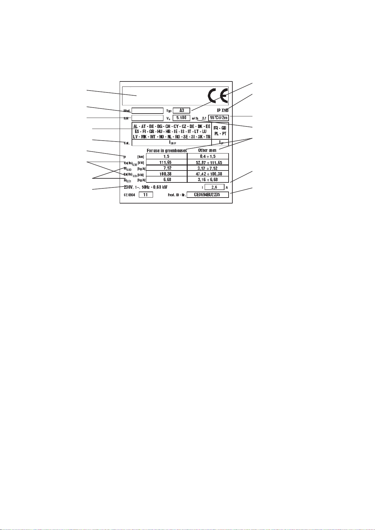
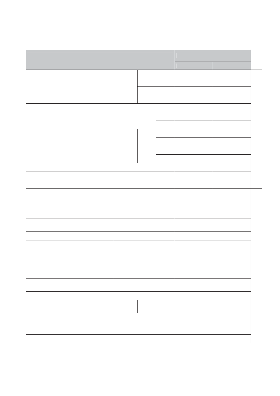
Les générateurs d'air chaud peuvent fonctionner avec du gaz
propane (G31) ou avec un mélange GPL de gaz butane (G30) et de
gaz propane (G31), conformément aux catégories de gaz indiquées
dans le Tab. I et mentionnées sur la plaquette d'identification de la
machine.
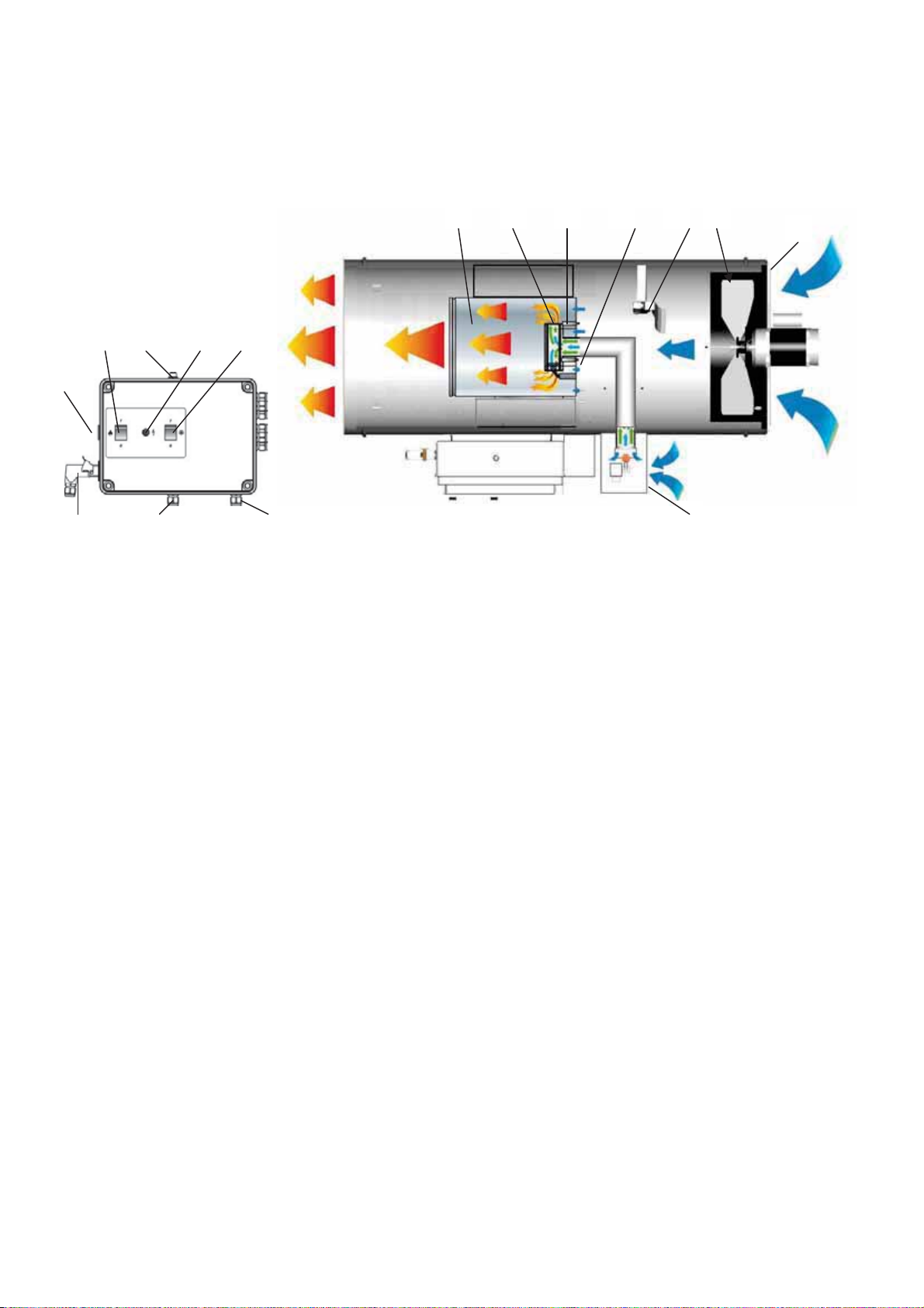
Les générateurs d'air chaud sont à combustion indirecte. L'air est
chauffé en utilisant l'énergie thermique développée pendant la
combustion puis envoyé au local à chauffer avec les produits de la
combustion sont éliminés à travers un conduit de cheminée : le local
devra toujours être correctement aéré afin d'assurer un recyclage
d'air suffisant.
Plusieurs dispositifs de sécurité (système électronique de
surveillance, thermostat de température excessive LI,
microinterrupteur ou pressostat de l'air) interviennent en cas de
dysfonctionnement grave :
• L'appareillage électronique de contrôle du brûleur intervient
lorsque la flamme est irrégulière ou qu'elle s'éteint ou encore
lorsque la tension d'alimentation devient trop faible (T < 190 V
pendant plus de 20 secondes) ;
• le thermostat de température excessive LI intervient si la
température de la chambre de combustion franchit le seuil de
sécurité ;
• l'interrupteur de flux d'air minimum (3) intervient en cas
d'insuffisance du débit d'air.
Dans chacun des cas décrits, le fonctionnement du générateur
d'air chaud s'arrête définitivement ou temporairement en fonction de
l'anomalie rencontrée et le témoin du poussoir de réarmement (8)
s'allume :
• si le témoin s'allume jaune, la machine est en arrêt temporaire ;
elle se remettra automatiquement en marche lorsque la
condition de défaut sera restaurée (basse tension.).
• Si le témoin s'allume rouge, la machine s'arrête définitivement
en mode "panne" ; elle ne peut être remise en marche qu'après
pression du poussoir de réarmement (8.).
AttentionLorsque le témoin rouge (8) est allumé, le générateur
est en condition de "panne" : cette condition est un
signal d'ANOMALIE.
Il est indispensable de toujours repérer la cause de la
panne et de la résoudre avant de remettre le
générateur en marche (Cf. "ANOMALIES DE
FONCTIONNEMENT, CAUSES ET SOLUTIONS").
Les générateurs d'air chaud de la série GA/N peuvent être
complétés par toute une série d'accessoires :
a) Horloge programmateur ou thermostat d'ambiance ou autre
dispositif électromécanique pour la commande automatique de
mise en marche et d'arrêt.
b) Kit pour le contrôle à distance par PC.
c) Kit pour le contrôle à distance par tableau (distance maxi 5
mètres), très utile lorsque l'installation au plafond ou dans un
local exigu empêche ou limite l'accès au tableau de commande
d) Kit pour le démarrage différé du générateur, très utile en cas
d'installation multiple pour éviter la surcharge de la ligne
d'alimentation électrique
e) Kit anti-condensation, indispensable pour les installations dans les
locaux à fort taux d'humidité (serres, élevages etc.) pour
supprimer les risques de défaut d'allumage.
CONSEILS D'ORDRE GÉNÉRAL
L'installation, le réglage et l'utilisation du générateur d'air chaud
doivent être accomplis dans le respect de toutes les normes, lois
nationales et locales en vigueur concernant l'utilisation de la
machine.
Le générateur d'air chaud peut être installé suspendu au plafond à
l'aide d'élingues et/ou de chaînes de dimension et longueur
appropriées, à fixer aux 4 crochets de suspension.
Attention S'assurer que les élingues et/ou chaînes forment un
angle maximum de 5° par rapport à la verticale au
plafond.
Il doit toujours être installé à une distance d'au moins 1 mètre de
toute cloison, sol et/ou plafond et d'au moins 300 mm du sol.
AttentionIl est interdit d'utiliser la machine sur un sol en
matériaux inflammables.
La distance minimum des sorties d'air de tout objet, personne
et/ou animal doit être d'au moins 2 mètre. Avant l'installation il est
toutefois indispensable de vérifier que lesdits objet, personne et
animal sont en mesure de supporter la température maximale de
sortie, qui peut être calculée à partir du total de la température
ambiante + ǻT @ 2 m (comme indiqué sur l'étiquette appliquée sur le
générateur d'air chaud).
AttentionIl est dangereux d'utiliser la machine dans des locaux
en sous-sol ou semi-enterrés.
Il convient de toujours s'assurer que :
• Les instructions du présent livret sont scrupuleusement
respectées ;
• Le générateur n'est pas installé dans des zones à fort risque
d'incendie ou d'explosion ;
• Aucun matériau inflammable n'est déposé à proximité de
l'appareil (la distance minimum doit être de 3 mètres) ;
• Tout risque de surchauffe des cloisons ou plafond réalisé dans
des matériaux inflammable a été analysé et écarté
• Toutes les mesures aptes à prévenir les incendies ont été
adoptées ;
• L'aération du local dans lequel est installé le générateur est
garantie et suffit aux besoins du brûleur ; en particulier les
limites relatives à la qualité de l'air du local à chauffer doivent
respecter les réglementations nationales ou locales en vigueur
ou, faute de normes et/ou indications, les termes de la norme
EN 1596:2008:

FR
11
• le volume minimum du local à chauffer doit être déterminé selon
un rapport puissance thermique / volume égal à 100 W/m3. Le
volume du local à chauffer ne doit en aucun cas être inférieur à
100 m3. ;
• une aération minimum avec l'extérieur de 25 cm2 par kW de
puissance thermique doit être garantie, avec un minimum de
250 cm2, correctement réparti entre partie haute et partie
basse.
• Il n'existe aucun obstacle ni obstruction aux conduits
d'admission et/ou d'évacuation de l'air, tels que bâches ou
couvertures posées sur l'appareil ou parois ou objets
encombrants placés trop près du générateur ;
• Le générateur est installé à proximité d'un coffret électrique
d'alimentation possédant des caractéristiques conformes à
celles déclarées ;
• Une position fixe a été prévue pour l'appareil ;
• Le jet d'air chaud ne soit pas orienté vers la bouteille.
• Le générateur est régulièrement surveillé pendant son
fonctionnement et contrôlé avant sa mise en marche ;
• Au début de chaque période de fonctionnement, aucun obstacle
n'entrave la rotation du ventilateur avant de brancher la fiche
dans la prise du réseau ;
• À la fin de chaque période de fonctionnement, le sectionneur
principal est désactivé et la vanne d'arrêt du gaz est fermée.
AttentionCet appareil ne doit pas être utilisé par des personnes
ou des enfants présentant un handicap physique,
sensoriel, mental ou ne possédant pas l'expérience et
les connaissances suffisantes à moins qu'ils aient été
formés sur son fonctionnement par une personne
responsable de la sécurité.
INSTRUCTIONS D'INSTALLATION
AttentionToutes les instructions fournies dans ce paragraphe
ne doivent être exécutées que par un personnel
qualifié.
BRANCHEMENTS ÉLECTRIQUES
AttentionLa ligne d'alimentation électrique doit être équipée
d'une mise à la terre et d'un disjoncteur
magnétothermique avec différentiel.
Le câble d'alimentation doit être branché à un coffret
électrique muni d'un sectionneur.
Tous les dispositifs de surveillance et de sécurité sont déjà
électriquement connectés.
Avant la mise en fonction du générateur donc avant de le brancher
au réseau électrique, il est indispensable de vérifier que les
caractéristiques du réseau d'alimentation électrique correspondent à
celles reportées sur la plaquette d'identification.
AttentionLa machine est dotée d'un câble d'alimentation
provisoire, utilisé pour le contrôle du fonctionnement.
Le câble d'alimentation provisoire doit être remplacé
par un câble de type H07RN-F d'une section de 1,5
mm². Retirer la gaine de protection du câble en veillant
à ce que la longueur du conducteur de terre soit
supérieure de 2 cm à celle des autres.
Le câble d'alimentation électrique doit être branché en respectant
les polarités indiquées sur le bornier principal du tableau électrique,
phase (L) et neutre (N.)
AttentionEn cas de non-respect des polarités L et N, le
générateur d'air chaud peut s'arrêter même après
quelques secondes suite à la première mise en
marche.
Le branchement éventuel du thermostat d'ambiance ou d'autres
accessoires de l'installation (ex. horloge) doit être effectué en
connectant le câble électrique à la fiche du thermostat (10) :
• Débrancher la fiche (10) du coffret électrique, l'ouvrir et retirer le
pontet électrique entre les bornes 2 et 3 de la fiche.
• Brancher le câble électrique au thermostat sur les bornes 2 et 3
de la fiche du thermostat (10)
• Refermer la fiche et la rebrancher dans la prise du coffret
électrique
AttentionNe jamais essayer de mettre en marche ou d'arrêter le
générateur en branchant le thermostat d'ambiance (ni
aucun autre dispositif de contrôle) sur la ligne
d'alimentation électrique.
L'installation et le branchement de tous les autres accessoires
sont indiqués dans les instructions spécifiques annexées à chaque
dispositif accessoire, à l'instar des instructions d'utilisation
spécifiques.
Le schéma électrique reporté dans ce manuel n'indique que le
branchement électrique de l'accessoire au circuit électrique du
générateur d'air chaud.
RACCORDEMENT À LA BOUTEILLE DE GAZ
Le générateur d'air chaud doit être raccordé à une bouteille de gaz
de dimensions appropriées, après interposition d'une vanne d'arrêt
de gaz
AttentionTous les raccords ont un filetage "gauche". Ils doivent
donc être vissés en tournant dans le sens contraire
des aiguilles d'une montre.
AttentionLes dimensions de la bouteille de gaz doivent être
déterminées avec précision, en fonction du débit de
gaz requis et de la pression d'alimentation.
La pression d'alimentation au manodétendeur doit
toujours être supérieure à 2 bars.

FR
12
Le générateur d'air chaud est livré avec tuyau de gaz (a) et
manodétendeur (c) avec raccords (d) adaptés au raccordement de
bouteilles de différents types.
En fonction du pays de destination, le générateur d'air chaud peut
être fourni avec trois types de manodétendeurs.
MODE I
• manodétendeur avec raccord de type G5 pour AT-BG-CY-DA-
DE-EE-LT-LV-MK-MT-RO-TR.
• raccord G5/G2, avec fixation de type G2 pour BE-CZ-ES-FR-
HR-HU-LU-PL-PT-SI-SK.
• raccord G5/G1, avec fixation type G1 pour IT-GR
• joint pour NL, à appliquer sur manodétendeur de type G5
AttentionL'installateur est tenu de vérifier que le raccord utilisé
est adapté au raccordement au type de bouteille de
gaz utilisé.
Visser toujours le raccord d'abord sur la bouteille et
ensuite seulement le manodétendeur muni d'un
raccord rotatif.
MODE II
• manodétendeur avec raccord de type G7 pour FI - IE - GB.
MODE III
• manodétendeur avec raccord de type G9 pour SE - NO.
AttentionL'étanchéité des jonctions doit être contrôlée en
appliquant du savon liquide : la présence éventuelle
de bulles est révélatrice d'une fuite de gaz.
Sur demande, il est possible de disposer de la sécurité stop-gaz
pour rupture du tuyau de gaz (b) ; cette sécurité doit obligatoirement
être installée si la réglementation ou la législation locale l'impose.
AttentionL'UTILISATION EN SERRE n'est autorisée aux termes
de la norme UNI EN 12669 :2003 que si le
manodétendeur est bloqué sur la position
correspondant à la pression d'alimentation maximum
(1,5 bars) à l'aide du dispositif de blocage (f) et de la
vis de serrage (g.)
L'installateur et l'utilisateur sont tenus de contrôler le
bon respect de cette consigne de fonctionnement.
Le changement et le remplacement de la bouteille de gaz doivent
être effectués en milieu ouvert, loin de toute source de chaleur et de
flamme libre en veillant au bon respect des consignes énoncées
dans ce paragraphe.
AttentionSi le type de fixation le prévoit, toujours contrôler que
le joint est bien positionné entre le manodétendeur et
la bouteille.
S'assurer que le tuyau de gaz flexible soit serré sans
torsion : les torsions éventuelles peuvent
endommager fortement le tuyau de gaz.
INSTRUCTIONS D'UTILISATION
MISE EN MARCHE
Pour mettre le générateur en marche (Fig. 1):
• Vérifier que l'interrupteur (9) est bien sur la position “0” ;
• Alimenter l'appareil en agissant sur l'interrupteur général du
coffret électrique d'alimentation ;
• Préselectionner le mode post-ventilation (ventilation de
refroidissement du générateur d'air chaud lors de l'extinction de
la flamme) en plaçant le commutateur (14) sur (0) pour post-
ventilation temporisée (90 secondes après l'extinction de la
flamme le ventilateur s'arrête également) ou sur (I) pour post-
ventilation continue (le ventilateur reste constamment en
fonction).
• Placer le commutateur (9) sur la position (I);
• Le fonctionnement est automatique uniquement si un
thermostat ou un autre dispositif de contrôle est branché à la
fiche du thermostat (10).
• Si au terme de ces opérations le générateur ne fonctionne pas,
consulter le paragraphe "ANOMALIES DE
FONCTIONNEMENT, CAUSES ET SOLUTIONS" et rechercher
la raison du dysfonctionnement.
AttentionEn cas de fuite de gaz, fermer immédiatement la vanne
d'arrêt de gaz et le robinet de la bouteille de gaz.
Éteindre le générateur d'air chaud, débrancher la prise
au tableau électrique et contacter l'assistance
technique qui recherchera l'origine de la fuite de gaz.
ARRÊT
Pour interrompre le fonctionnement de l'appareil, agir sur le
commutateur (9), en le plaçant sur la position "0" en fonctionnement
manuel ou sur le thermostat d'ambiance en fonctionnement
automatique.
Fermer la vanne d'arrêt du gaz et sectionner l'alimentation.
La flamme s'éteint et le moteur du ventilateur continue de
fonctionner selon le mode programmé (post-ventilation temporisée
ou post-ventilation continue).
VENTILATION
Pour n'obtenir que l'effet ventilation, il suffit de placer le
commutateur (14) sur la position portant le symbole (I) pour mettre la
machine en marche : le ventilateur principal se met en marche mais
le brûleur reste éteint.
TRANSPORT ET MANUTENTION
Le générateur d'air chaud peut être soulevé et suspendu à l'aide
des quatre crochets d'ancrage aménagés sur son bâti.
AttentionAvant tout déplacement :
• Arrêter le générateur en suivant les consignes
fournies au paragraphe "ARRÊT" ;
• Débrancher l'alimentation électrique en retirant la
fiche de la prise ;
• Fermer la vanne d'arrêt de gaz et débrancher le
tuyau de gaz ;
• Attendre que le générateur soit froid.
AttentionAu cours du transport et/ou du stockage, s'assurer
que le groupe soupape gaz et tuyau de liaison gaz ne
sont exposé à aucun risque de choc ou
d'endommagement.
MAINTENANCE
Pour garantir un fonctionnement optimal de l'appareil, il est
nécessaire de nettoyer régulièrement le moteur du ventilateur, la
chambre de combustion et le brûleur et de retirer tout corps étranger
éventuel.
En particulier, il est essentiel de veiller à ce que la grille
d'aspiration d'air du ventilateur (A) et la grille d'aspiration d'air de
combustion (B) (Fig. 1) soient constamment propres et dépourvues
de tout corps étranger.
Attention Avant toute opération d'entretien il est impératif de :
• Arrêter le générateur en suivant les consignes
fournies au paragraphe "ARRÊT" ;
• Débrancher l'alimentation électrique en retirant la
fiche de la prise ;
• Fermer la vanne d'arrêt du gaz ;
• Attendre que le générateur soit froid.

FR
13
Le générateur peut être nettoyé et lavé à l'eau. Il est alors
nécessaire de s'assurer que :
• le câble d'alimentation électrique a été débranché et retiré de la
prise d'alimentation
• tous les carters d'accès ont été complètement fermés
• la pression maximale des jets d'eau ne dépasse pas 150 bars et
que la distance ne soit pas inférieure à 30 cm.
• chacun des éléments du générateur est parfaitement sec avant
de rebrancher le câble d'alimentation électrique
Attention Toute modalité impropre de nettoyage du générateur
peut causer des dommages aux biens et/ou aux
personnes.

FR
14
ANOMALIES DE FONCTIONNEMENT, CAUSES ET SOLUTIONS
ANOMALIES DE
FONCTIONNEMENT CAUSES SOLUTIONS
• Vérifier les caractéristiques de l'alimentation
électrique
• Vérifier les branchements électriques
• Manque d'alimentation électrique
• Vérifier que le fusible est intact
• Mauvaise position de l'interrupteur général • Placer l'interrupteur sur la position correcte
• Vérifier la position du thermostat
• Fonctionnement irrégulier du thermostat
d'ambiance • Vérifier le fonctionnement du thermostat
• Vérifier que les grilles de l’aspiration et de
l’évacuation ne sont pas obstruées
• Vérifier que le ventilateur tourne librement
• Intervention du pressostat d'air suite au
dysfonctionnement du ventilateur
• Vérifier le moteur électrique et le condensateur et
les remplacer s'ils sont défectueux
• Le générateur ne démarre pas
• Intervention du pressostat d'air suite au
dysfonctionnement du pressostat • Remplacer le pressostat
• Lorsque la valeur de tension correcte est rétablie
(> 195 V), le générateur redémarre
automatiquement.
• Si le générateur démarre et s'arrête à plusieurs
reprises, contrôler la ligne d'alimentation
électrique.
• Le générateur ne démarre pas ou
il s'arrête et le témoin lumineux
s'allume (8) avec diode orange
clignotante
• Alimentation électrique insuffisante (tension <
195 V)
• Si le générateur ne démarre pas et reste en
condition de panne, contrôler la ligne
d'alimentation électrique.
• Lors du branchement du câble d'alimentation
électrique, les polarités L et N ont été inversées. • Inverser les polarités L et N
• L'électrode d'ionisation ne détecte pas la
présence de flamme • Retirer le capteur de flamme et le nettoyer
• Vérifier que les grilles de l'aspiration et de
l'évacuation ne sont pas obstruées
• Vérifier que le local est correctement aéré
• Contrôler que l'air chaud peut sortir librement
• Intervention du thermostat de sécurité suite à
surchauffe de la chambre de combustion
• Contrôler que le débit ou la pression des gaz
n'est pas excessif
• Intervention du système de surveillance suite au
fonctionnement irrégulier du brûleur • Contacter l'Assistance technique
• Système électronique de surveillance défectueux • Contrôler le système et le remplacer si
nécessaire
• Le générateur s'arrête et le témoin
(8) rouge clignote
• Thermostat défectueux • Contrôler le thermostat et le remplacer si
nécessaire
• Intervention du thermostat du brûleur • Canaux de distribution d'air excessivement longs
ou de trop petit diamètre
• Le générateur s'arrête et repart et
le témoin (8) ne s'allume pas • Intervention du pressostat de gaz suite à la chute
soudaine de la pression d'alimentation • Contrôler la pression d'alimentation du gaz
• Des corps étrangers se trouvent sur les pales du
ventilateur • Retirer les corps étrangers
• Le ventilateur fait du bruit ou émet
des vibrations • La circulation d'air est insuffisante • Supprimer tous les obstacles pouvant gêner le
passage de l'air
Si malgré les contrôles et les remèdes décrits la cause du dysfonctionnement n'a pas été trouvée, contacter le centre d'assistance agréé
le plus proche.

EN
20
IMPORTANT
Before using the space heater, please read carefully all the instructions for use described below and follow the
indications scrupulously.
The manufacturer cannot be held responsible for damage to persons and/or property caused by improper use of
the equipment.
This instruction manual is an integral part of the equipment and must therefore be kept carefully and passed on
with the unit in the event of a change of ownership.
DESCRIPTION
Space heaters are designed for heating medium and large
ventilated premises, for which a fixed or mobile heating system is
required.
Warning DO NOT USE TO HEAT HABITABLE AREAS OF
RESIDENTIAL BUILDINGS.
REFER TO NATIONAL REGULATIONS FOR USE IN
PUBLIC BUILDINGS.
Space heaters can be run on propane gas (G31) or on L.P.G.
(butane G30 and propane G31) according to the different gas
categories indicated on Tab. I and shown on the heater
identification plate.
Space heaters are of the direct combustion type. The air is
heated by the thermal energy generated during combustion and
is then conveyed to the room to be heated with the products of
combustion: the room must in any case be suitably ventilated in
order to ensure adequate air circulation.
Various safety devices (electronic control unit, overheating
thermostat LI, microswitch or air pressure switch) trip in the event
of serious malfunction:
• the electronic burner control unit trips if the flame is irregular
or goes out or when the supply voltage drops too low (T <
190 V for more than 20 seconds);
• the overheating thermostat LI trips when the temperature of
the combustion chamber exceeds the safety limit;
• the air flow switch (3) trips if air flow is insufficient.
In each of the cases described above, the space heater stops
working (permanently or temporarily, depending on the cause)
and the reset button light (8) comes on:
• if the light is yellow, the heater stops temporarily and
automatically resumes work when the missing supply has
been restored (low voltage);
• if the light is red, the heater stops permanently in “block”
status and can be restarted only by pressing the reset
button (8).
Warning When light (8) is on and red, the heater is in
“block” status, which indicates a MALFUNCTION.
You must always identify the cause of the “block”
and eliminate it before restarting the heater (see:
“FAULTS, CAUSES AND REMEDIES”).
Space heaters can be completed with a series of accessories:
a) clock timer or room thermostat or a similar electromechanical
device for automatic switching on and off
b) kit for remote control from a Personal Computer
c) kit for control from the remote panel (max distance 5 m), useful
for ceiling-mounted installations or in restricted situations
where access to the control panel is limited
d) kit for delayed heater switching on, useful for multiple
installations to prevent overloading the electrical power supply.
e) anti-condensation kit, indispensable for installations under
very humid conditions (greenhouses, battery farming, etc.) to
solve the problem of ignition failure.
GENERAL ADVICE
Installation, setting up and use of the hot air generator must be
effected in accordance with the applicable regulations and laws
relating to the use of such equipment.
The space heater can be installed suspended from the ceiling
by means of cables and/or chains of suitable size and length to
fix to the 4 suspension hooks.
Warning Make sure that the cables and/or chains form a
maximum angle of 5°off vertical on the ceiling.
The minimum distance from surrounding walls, floor and/or
ceiling must be at least 1 m and the distance from the floor of at
least 500 mm.
Warning DO NOT use the heater on floors made with
flammable materials.
The minimum proximity of objects, property, persons and/or
animals to be kept in front of the air distribution area must be at
least 2 m, having checked that they can support the maximum
temperature, which can be found by adding the room
temperature + ǻT @ 2 m (as shown on the identification label
affixed to the space heater itself).
Warning Use in basements or below ground level is
hazardous.
Make sure that:
• The instructions in this manual are carefully followed;
• The generator is not installed in an area where there is a
high risk of fire or explosions;
• No flammable materials are stored in the vicinity of the
heater (the minimum distance must be at least 3 m)
• A check is made that there is no overheating of walls,
ceilings or floors made of flammable materials
• All precautions have been taken to prevent fires;
• The premises in which the heater is installed are sufficiently
ventilated for the burner requirements; in particular the limits
regarding the quality of the air in the room to be heated
must be complied with, as prescribed by the applicable
national or local laws or, in the absence of any standards
and/or indications, in compliance with the provisions of EN
1596:2008:
• minimum room volume must be measured with thermal
power/volume ratio equal to 100 W/m3. Room volume must
NEVER be less than 100 m3;
• a minimum ventilation area of 25 cm2 per kW of thermal
power must be provided, the minimum being 250 cm2,
divided equally between the upper and lower part.
• The air suction and/or supply hoses are not blocked in any
way, there are not sheets or covers resting on the machine
or walls and bulky objects near the generator;

EN
21
• The generator is placed near a power switchboard having
specifications that conform to those declared;
• The unit is placed in a fixed position
• The hot air jet is directed towards the cylinder.
• The heater is regularly monitored during operation and
checked before being started up;
• At the beginning of each working period, before plugging it
into the electrical power supply, a check is made that the
fan moves freely;
• At the end of each working period the main switch is
disengaged and the gas stopcock is closed.
Warning This unit may not be used by persons (including
children) with reduced physical, sensorial or
mental capacities or with limited experience and
familiarity unless they are under supervision or
instructed on how to use the equipment by the
person responsible for its safety.
INSTALLATION INSTRUCTIONS
Warning All the operations described in this section must
only be performed by professional and skilled
personnel.
POWER CONNECTIONS
Warning The power line of the generator must be fitted with
an earth lead and a residual current circuit breaker.
The supply cable must be connected to a
switchboard that has an isolation switch.
All the control and safety devices are already electrically
connected.
Before switching on the heater, and therefore, before plugging
it into the electrical power supply, a check must be made that the
power supply specifications are the same as those stated on the
identification plate.
Warning The equipment is fitted with a temporary power
cable, used for the working test.
The temporary power cable must be removed and
replaced with a H07RN-F cable having a 1.5 mm2
diameter. The cable must be stripped leaving the
earth conductor at least 2 cm longer.
The electrical power cable must be connected in conformity to
the polarity specified on the main terminal board of the electrical
panel: phase (L) and neutral (N).
Warning If polarities L and N are incorrect, the space heater
may stop a few seconds after it is switched on for
the first time.
If any room thermostat or other accessories are connected to
the system (such as the timer for example) this must be done by
connecting the electrical cable to the thermostat plug (10):
• Take the plug (10) out of the power switchboard, open it and
remove the electrical jumper between terminals 2 and 3 of
the plug.
• Connect the thermostat electrical cable to terminals 2 and 3
of the thermostat plug (10)
• Close the plug again and plug it back into the power
switchboard
Warning Never attempt to switch the heater on or off by
connecting the room thermostat (or other control
devices) to the electrical power line.
Installation and connection of all the other accessories are
given in the specific instructions enclosed with each accessory,
like the specific user instructions.
The electrical diagram in this manual indicates only the
electrical connection of the accessory to the existing electrical
system of the heater.
CONNECTION TO GAS CYLINDER
The heater must be connected to an appropriately sized gas
cylinder. A gas supply stopcock must be installed between the
heater and the cylinder
Warning All of the connections have left-hand threads, and
must therefore be tightened by turning
anticlockwise.
Warning The dimensions of the gas cylinder must be based
on the required gas flow rate and supply pressure.
The supply pressure to the pressure regulator
must always be greater than 2 bar
The heater is supplied complete with gas hose (a) and
pressure reducer (c) with fittings (d) for connection to different
types of cylinders.
Depending on the country of destination, the heater may be
supplied with three different types of gas pressure regulator.
TYPE I
• pressure regulator with G5 fitting for AT-BG-CY-DA-DE-EE-
LT-LV-MK-MT-RO-TR.
• G5/G2 fitting, with G2 fitting for G2 for BE-CZ-ES-FR-HR-
HU-LU-PL-PT-SI-SK.
• G5/G1 fitting, with G1 fitting for IT-GR
• seal for NL, to install on G5 pressure regulator
Warning The installer is responsible for guaranteeing that
the correct fitting is used for the connection to the
gas cylinder.

EN
22
Always tighten the cylinder fitting first, and then
the pressure regulator, which has a swivel fitting.
TYPE II
• pressure regulator with G7 fitting for FI - IE - GB.
TYPE III
• pressure regulator with G9 fitting for SE - NO.
Warning The seal of the fittings must be checked by
pouring liquid soap on them: the appearance of
bubbles indicates a possible gas leak.
A safety valve (b) may be ordered for protection in case of a
broken gas hose. Installation of this valve is mandatory if
required by local installation laws and regulations.
Warning USE IN GREENHOUSES is authorised by UNI EN
12669:2003 only if the regulator is locked in the
position for maximum supply pressure (1.5 bar) by
using lock stirrup (f) and lock screw (g).
The installer and the user are responsible for
checking that this operating instruction is
followed.
The gas cylinder must be changed and replaced in an open
room, away from sources of heat and without any open flame,
taking care to check that the instructions in this paragraph are
followed.
Warning Always make sure that the seal (if required by the
fitting) is present between the reducer and the
cylinder.
Make sure that the gas hose has been tightened
without being twisted: any stress from twisting can
seriously damage the hose.
OPERATING INSTRUCTIONS
START-UP
To start the space heater (Fig. 1):
• Make sure the switch (9) is set to “0”;
• Switch on power to the heater by means of the isolation
switch on the power switchboard;
• Preset the post-ventilation mode (the ventilation for cooling
the space heater when the flame is turned off) by setting
commutator (14) to position (0) for timed post-ventilation (90
sec after the flame goes out the fan stops as well) or to
position (I) for continuous post-ventilation (the fan works
continuously).
• Move the switch (9) to position (I);
• Operation will only be automatic if a thermostat or another
control device is connected to the thermostat plug (10).
• If after these operations, the generator does not work, refer
to the “FAULTS, CAUSES AND REMEDIES” section and
find the cause.
Warning In case of a gas leak, close the gas stopcock
immediately, close the gas cylinder valve, switch
off the heater, remove the plug from the electrical
panel, and call customer service to find the origin
of the leak.
STOP
To stop operation turn the switch (9), spostandolo nella
posizione “0”, to “0” if operation is manual, or to room thermostat
if operation is aut.
Lastly, close the gas supply stopcock and turn off the isolation
switch.
The flame goes out and the fan motor continues to work
according to the preset mode (timed post-ventilation or
continuous post-ventilation).
VENTILATION
To obtain the ventilation effect only, simply turn the switch (14)
to the position marked with the symbol (I): to start the machine:
the main fan starts while the burner stays off.
TRANSPORT AND HANDLING
The space heater can be lifted up and suspended using the
four anchor hooks provided in the casing.
Warning Before moving the unit:
• Stop the machine as indicated in the “STOP”
paragraph;
• Disengage the power supply by removing the
plug from the power socket;
• Close the gas stopcock and disconnect the gas
hose;
• Wait until the heater has cooled down.
Warning During transportation and/or storage, make sure
the gas valve group and gas connection pipes are
not knocked or damaged in any way.
MAINTENANCE
For efficient operation of the heater, clean the fan motor,
combustion chamber, and burner at regular intervals. Remove all
debris.
Specifically, both suction grid (A) for the fan air and suction
grid (B) for the combustion air (Fig. 1) must be kept clean and
free of all deposits and debris.
Warning Before performing any maintenance operations:
• Stop the machine as indicated in the “STOP”
paragraph;
• Disengage the power supply by removing the
plug from the power socket;
• Close the gas supply stopcock;
• Wait until the heater has cooled down.
The heater can be cleaned and washed with water. It is
however necessary to ensure that:
• the power lead is disconnected and unplugged from the
power supply socket
• all access panels have been completely closed
• water jets with maximum pressure of 150 bar and at a
distance exceeding 30 cm. are used
• all parts of it are completely dry before plugging in the
power lead again
Warning Cleaning the heater by the wrong procedures can
cause damage to things and/or persons.

EN
23
FAULTS, CAUSES AND REMEDIES
FAULTS CAUSES REMEDIES
• Check power specifications
• Check power connections
• No power supply
• Check fuse
• Main switch in wrong position • Select correct position
• Check thermostat position
• Faulty operation of room thermostat • Check thermostat operation
- Check that the suction and the flow grills are
unobstructed
- Check that the fan is running freely
• Air pressure switch tripped due to fan malfunction
- Check the electric motor and the condenser and,
if faulty, replace them
• The heater fails to start
• Air pressure switch tripped due to pressure
switch malfunction • Replace the pressure switch
• The heater will restart automatically when the
power supply returns to normal (V>195V)
• If the heater starts and stops several times check
the electrical power supply
•The heater fails to start or stops
and the warning light (8) comes on
with a flashing orange light.
• Power supply too low (V < 195 V)
• If the heater will not start and remains off, check
the electrical power supply
• Electrical power cable is connected with polarities
L and N reversed • Reverse polarities L and N
• The ionisation electrode does not detect a flame • Remove the flame sensor and clean it
• Check that the suction and the flow grills are
unobstructed
• Check that the room is well ventilated
• Check that the hot air can escape freely
• Safety thermostat tripped due to the combustion
chamber overheating
• Check that the gas flow or pressure are not
excessive
• Control unit tripped due to irregular burner
operation • Contact Service Assistance
• Faulty electronic control unit • Check the unit and if necessary replace it
• The heater fails to start or stops
and the warning light (8) comes on
with steady red light
• Faulty thermostat • Check the thermostat and if necessary replace it
• Burner thermostat tripped • Air distribution ducts too long or with insufficient
diameter
• The heater stops and then starts
again but the warning light (8) does
not come on • Gas pressure switch tripped due to sudden drop
in gas supply pressure • Check the gas supply pressure
• Foreign bodies on fan blades • Remove foreign bodies
• Fan noise or vibrations • Little air circulation • Eliminate all possible obstacles to proper air flow
If the cause of the malfunction has not been found with the above checks and remedies, please contact your nearest dealer or authorised
service centre.

11
SCHEMA ELETTRICO - SCHEMA ELECTRIQUE – SCHALTSCHEMA WIRING DIAGRAM - ESQUEMA
ELETRICO - ɗɅȿɄɌɊɂɑȿɋɄȺə ɋɏȿɆȺ

35
SCHEMA ELETTRICO - SCHEMA ELECTRIQUE – SCHALTSCHEMA WIRING DIAGRAM - ESQUEMA
ELETRICO – ɗɅȿɄɌɊɂɑȿɋɄȺə ɋɏȿɆȺ
AP APPARECCHIATURA DI CONTROLLO
COFFRET DE SECURITE
STEÜRGERÄT
CONTROL BOX
APARATO DE CONTROL
ɄɈɇɌɊɈɅɖɇɈȿ ɈȻɈɊɍȾɈȼȺɇɂȿ
ST SPIA TENSIONE
LAMPE TEMOIN D’ALIMENTATION
STROMANZEIGLAMPE
ELECTRIC PILOT LAMP
TESTIGO TENSIóN
ɂɇȾɂɄȺɌɈɊ ɇȺɉɊəɀȿɇɂə
FU FUSIBILE
FUSIBLE
SICHERUNG
FUSE
FUSIBLE
ɉɊȿȾɈɏɊȺɇɂɌȿɅɖ
EV RAMPA GAS
ELECTROVANNE
MAGNETVENTIL
GAS TRAIN
ELECTROVÁLVULA
ɗɅȿɄɌɊɈɄɅȺɉȺɇ
CO CONDENSATORE
CONDENSATEUR
KONDENSATOR
CONDENSER
CONDENSADOR
ɄɈɇȾȿɇɋȺɌɈɊ
MV MOTORE VENTILATORE
MOTEUR DU VENTILATEUR
VENTILATOR MOTOR
FAN MOTOR
MOTOR VENTILADOR
ȾȼɂȽȺɌȿɅɖ ȼȿɇɌɂɅəɌɈɊȺ
FUA FUSIBILE
FUSIBLE
SICHERUNG
FUSE
FUSIBLE
ɉɊȿȾɈɏɊȺɇɂɌȿɅɖ
RV INTERRUTTORE RISCALDAMENTO
INTERRUPTEUR CHAUFFAGE
SCHALTER HEIZUNG
HEATING SWITCH
INTERRUPTOR DE LA CALEFACCIÓN
ȼɕɄɅɘɑȺɌȿɅɖ ɇȺȽɊȿȼȺ
LF FILTRO ANTIDISTURBO
FILTRE ANTIPARASITES
FUNKENTSTöRFILTER
ANTI-JAMMING FILTER
FILTRO ANTI MOLESTIA
ɉɈɆȿɏɈɁȺɓɂɓȿɇɇɕɃ ɎɂɅɔɌɊ
IT TRASFORMATORE A.T.
TRANSFORMATEUR H.T.
ZÜNDTRANSFO
TRANSFORMER H.V.
TRANSFORMADOR A.T.
ɌɊȺɇɋɎɈɊɆȺɌɈɊ ȼɕɋɈɄɈȽɈ ɇȺɉɊəɀȿɇɂə
PA PRESSOSTATO ARIA
PRESSOSTAT AIR
LUFTPRESSOSTAT
AIR PRESSURE SWITCH
PRESOSTATO DE AIRE
ɊȿɅȿ ȾȺȼɅȿɇɂə ȼɈɁȾɍɏȺ
EI ELETTRODO DI IONIZZAZIONE
ÉLECTRODE D'IONISATION
IONISATIONSELEKTRODE
IONISATION ELECTRODE
ELECTRODO DE IONIZACIÓN
ɂɈɇɂɁɂɊɍɘɓɂɃ ɗɅȿɄɌɊɈȾ
RV1 INTERRUTTORE VENTILAZIONE
INTERRUPTEUR VENTILATION
SCHALTER LÜFTUNG
VENTILATION SWITCH
INTERRUPTOR VENTILACIÓN
ȼɕɄɅɘɑȺɌȿɅɖ ȼȿɇɌɂɅəɐɂɂ
LI TERMOSTATO DI SICUREZZA
THERMOSTAT DE SURCHAUFFE
SICHERHEITSTHERMOSTAT
OVERHEAT THERMOSTAT
TERMOSTATO DE SEGURIDAD
ɉɊȿȾɈɏɊȺɇɂɌȿɅɖɇɕɃ ɌȿɊɆɈɋɌȺɌ
RE RELE MOTORE VENTILATORE
RELAIS MOTEUR VENTILATEUR
RELAIS VENTILATORMOTOR
FAN MOTOR RELAY
RELÉ MOTOR VENTILADOR
ɊȿɅȿ ȾȼɂȽȺɌȿɅə ȼȿɇɌɂɅəɌɈɊȺ
RE1 RELE DI VENTILAZIONE CONTINUA
RELAIS VENTILATION CONTINUE
RELAIS KONTINUIERLICHE BELÜFTUNG
CONTINUOUS VENTILATION RELAY
RELÉ VENTILACIÓN CONTINUA
ɊȿɅȿ ɉɈɋɌɈəɇɇɈɃ ȼȿɇɌɂɅəɐɂɂ
RE2 RELE DI RITARDO ACCENSIONE
RELAIS RETARD ALLUMAGE
RELAIS ANLAUFVERZÖGERUNG
DELAYED IGNITION RELAY
RELÉ RETARDO ENCENDIDO
ɊȿɅȿ ȼɄɅɘɑȿɇɂə ɉɈ ȼɊȿɆȿɇɂ
RL SPIA BLOCCO REMOTO
TÉMOIN BLOCAGE À DISTANCE
KONTROLLLEUCHTE FERNBLOCKIERUNG
REMOTE BLOCK INDICATOR LIGHT
TESTIGO BLOQUEO REMOTO
ɂɇȾɂɄȺɌɈɊ ȾɂɋɌȺɇɐɂɈɇɇɈɃ ȻɅɈɄɂɊɈȼɄɂ
RRESISTENZA ANTICONDENSA
RÉSISTANCE ANTI-CONDENSATION
KWIDERSTAND KONDENSATSCHUTZ
ANTI-CONDENSATION RESISTANCE
RESISTENCIA ANTICONDENSACIÓN
ɋɈɉɊɈɌɂȼɅȿɇɂȿ ɉɊɈɌɂȼ ɈȻɊȺɁɈȼȺɇɂə ɄɈɇȾȿɇɋȺɌȺ
PG PRESSOSTATO GAS
PRESSOSTAT GAZ
GASPRESSOSTAT
GAS PRESSURE SWITCH
PRESOSTATO DE GAS
ɊȿɅȿ ȾȺȼɅȿɇɂə ȽȺɁȺ
AM KIT ANTICONDENSA
KIT ANTI-CONDENSATION
SET KONDENSATSCHUTZ
ANTI-CONDENSATION KIT
KIT ANTICONDENSACIÓN
ɄɈɆɉɅȿɄɌ ɉɊɈɌɂȼ ɈȻɊȺɁɈȼȺɇɂə ɄɈɇȾȿɇɋȺɌȺ
RP KIT CONTROLLO REMOTO DA PANNELLO (L=5m)
KIT CONTRÔLE À DISTANCE PAR TABLEAU (L=5 M)
SET FERNBEDIENUNG ÜBER BEDIENPANEEL (L = 5M)
KIT FOR REMOTE CONTROL FROM PANEL (L = 5M)
KIT CONTROL REMOTO DESDE PANEL (L = 5M)
ɄɈɆɉɅȿɄɌ ȾɂɋɌȺɇɐɂɈɇɇɈȽɈ ɍɉɊȺȼɅȿɇɂə ɋ ɉȺɇȿɅɂ (5 Ɇ)
PC KIT CONTROLLO REMOTO DA PC
KIT CONTRÔLE À DISTANCE PAR PC
SET FERNBEDIENUNG VON PC
KIT FOR REMOTE CONTROL FROM PC
KIT CONTROL REMOTO DESDE PC
ɄɈɆɉɅȿɄɌ ȾɂɋɌȺɇɐɂɈɇɇɈȽɈ ɍɉɊȺȼɅȿɇɂə ɋ ɉɄ
DS KIT TEMPORIZZATO PER PARTENZA RITARDATA
KIT TEMPORISATEUR POUR DÉMARRAGE DIFFÉRÉ
SET ZEITSCHALTER FÜR ANLAUFVERZÖGERUNG
TIMER KIT FOR DELAYED IGNITION
KIT TEMPORIZADOR PARA PARTIDA RETARDADA
ɄɈɆɉɅȿɄɌ ɉɊɈɌɂȼ ɈȻɊȺɁɈȼȺɇɂə ɄɈɇȾȿɇɋȺɌȺ
TA PRESA TERMOSTATO AMBIENTE
PRISE THERMOSTAT D’AMBIACE
RAUMTHERMOSTAT STECKDOSE
ROOM THERMOSTAT PLUG
ENCHUFE TERMOSTATO AMBIENTE
ɊȺɁɔȿɆ ɌȿɊɆɈɋɌȺɌȺ ɈɄɊɍɀȺɘɓȿɃ ɋɊȿȾɕ
MO MORSETTIERA COLLEGAMENTO KIT CONTROLLO REMOTO
BORNIER POUR BRANCHEMENT KIT CONTRÔLE À DISTANCE
ANSCHLUSSLEISTE FERNBEDIENUNGS-SET
TERMINAL BLOCK FOR CONNECTING REMOTE CONTROL KIT
BORNERA PARA CONEXIÓN KIT CONTROL REMOTO
ɄɅȿɆɆɇɂɄ ȾɅə ɉɈȾɋɈȿȾɂɇȿɇɂə ɄɈɆɉɅȿɄɌȺ
ȾɂɋɌȺɇɐɂɈɇɇɈȽɈ ɍɉɊȺȼɅȿɇɂə

36
GA 100C
CARATTERISTICHE TECNICHE - CARACTERISTIQUES TECHNIQUES
TECHNISCHEN DATEN - TECHNICAL SPECIFICATIONS
CARACTERÍSTICAS TÉCNICAS - ɌȿɏɇɂɑȿɋɄɂȿ ɏȺɊȺɄɌȿɊɂɋɌɂɄɂ
Use in greenhouse Other uses
[kW]
92,25 43,58 - 92,25
Hi
[kcal/h]
79.332 37479 - 79332
[kW]
100,38 47,42 - 100,38
Potenza termica max - Puissance thermique max
Wärmeleistung max - Max heating output
Potencia térmica máx - Ɇɚɤɫɢɦɚɥɶɧɚɹ ɬɟɩɥɨɜɚɹ ɦɨɳɧɨɫɬɶ H
Hs
[BTU/h]
345.295 163128 - 345295
Pressione gas - Pression gaz - Betriebs druck
Gas pressure - Presión gas - Ⱦɚɜɥɟɧɢɟ ɝɚɡɚ [bar]
1,5 0,4 - 1,5
[m
3
/h]
12,68 5,99 - 12,68
Consumo – Consommation - Brennstoffverbr.
Consumption - Consumo - Ɋɚɫɯɨɞ [kg/h]
6,68 3,16 - 6,68
G 31 - PROPANE
[kW]
102,92 48,83 - 102,92
Hi
[kcal/h]
88.508 41994 - 88508
[kW]
111,65 52,97 - 111,65
Potenza termica max - Puissance thermique max
Wärmeleistung max - Max heating output
Potencia térmica máx - Ɇɚɤɫɢɦɚɥɶɧɚɹ ɬɟɩɥɨɜɚɹ ɦɨɳɧɨɫɬɶ H
Hs
[BTU/h]
384.069 182228 - 384069
Pressione gas - Pression gaz - Betriebs druck
Gas pressure - Presión gas - Ⱦɚɜɥɟɧɢɟ ɝɚɡɚ [bar]
1,5 0,4 - 1,5
[m
3
/h]
11,71 5,55 - 11,71
Consumo – Consommation - Brennstoffverbr.
Consumption - Consumo - Ɋɚɫɯɨɞ [kg/h]
7,52 3,57 - 7,52
G 30 - BUTHANE
Portata d'aria - Débit d'air - Nenn-Lufleistung
Air output - Capacidad aire - Ɇɨɳɧɨɫɬɶ ɩɨɞɚɱɢ ɜɨɡɞɭɯɚ [m
3
/h]
5.100
Protezione IP - Protection IP - Schutz IP
IP protection - Protección IP - Ʉɥɚɫɫ ɡɚɳɢɬɵ IP
IP X5D
Temperatura min. di servizio - Température min. de service
Min. Service-Temperatur - Min. service temperature
Temperatura mín. de servicio - Ɇɢɧɢɦɚɥɶɧɚɹ ɪɚɛɨɱɚɹ ɬɟɦɩɟɪɚɬɭɪɚ
[°C]
-20
Temperatura max. di servizio - Température max. de service
Max. Service-Temperatur - Max. service temperature
Temperatura máx. de servicio - Ɇɚɤɫɢɦɚɥɶɧɚɹ ɪɚɛɨɱɚɹ ɬɟɦɩɟɪɚɬɭɪɚ
[°C]
40
Tipo - Type - Typ
Type - Tipo - Ɍɢɩ
A
3
Fase – Phase
Phase – Phase
Fase - ɑɢɫɥɨ ɮɚɡ
1
Tensione - Tension
Spannung - Voltage
Ténsion - ɇɚɩɪɹɠɟɧɢɟ
[V]
230
Alimentazione elettrica - Alimentatione électrique
Netzanscluss - Power supply
Alimentación eléctrica - ɗɥɟɤɬɪɨɩɢɬɚɧɢɟ
Frequenza - Fréquence
Frequenz - Frequency
Frecuencia - ɑɚɫɬɨɬɚ
[Hz]
50
Potenza elettrica totale - Puissance électrique
Leistunsaufnahme - Total power consumption
Potencia eléctrica total - ɉɨɥɧɚɹ ɷɥɟɤɬɪɢɱɟɫɤɚɹ ɦɨɳɧɨɫɬɶ
[W]
600
Assorbimento elettrico – Puissance absorbée – Stromaufnahme
Current draw – Absorción eléctrica – ɉɨɬɪɟɛɥɟɧɢɟ ɷɥɟɤɬɪɨɷɧɟɪɝɢɢ [A]
2,6
Incremento di temperatura - Elévation de la température
Temperaturanstieg - Temperature rise
Aumento de la temperatura - ɩɨɜɵɲɟɧɢɟ ɬɟɦɩɟɪɚɬɭɪɵ
@2 m [°C]
55
Livello sonoro a 1 m - Niveau sonore à 1 m
Geraüschspegel a 1 m - Noise level at 1 m
Nivel sonoro a 1 m - ɍɪɨɜɟɧɶ ɲɭɦɚ ɧɚ ɪɚɫɫɬɨɹɧɢɢ 1 ɦ
[dBA]
77
Dimensioni, L x P x A - Dimensions, L x P x H - Masse, H x B x T -
Dimensions, L x W x H - Dimensiones, L x P x A - Ɋɚɡɦɟɪɵ,ɒɯȽɯȼ [mm]
1146 x 589 x 441
Peso – Poids - Gewicht
Weight - Peso - ȼɟɫ [kg]
36

37
DESTINAZIONE EUROPEA - DESTINATION EUROPÉENNE
BESTIMMUNGSGEBIET EUROPEA – EUROPE
DESTINO EUROPEO - ȿȼɊɈɉȿɃɋɄȺə ɋɌɊȺɇȺ ɇȺɁɇȺɑȿɇɂə
Paese – Pays
Land – Country
País - ɋɬɪɚɧɚ
AL - AT - BE - BG - CH -
CY - CZ - DE - DK - EE -
ES - FI - GR - HU - HR - IE
- IS - IT - LT - LU - LV -
MK - MT - NO - NL - RO -
SE - SI - SK - TR
FR - GB - PL - PT
Categoria – Catégorie
Kategorie – Category
Categoría - Ʉɚɬɟɝɨɪɢɹ I3B/P I3P
Tipo di gas - Type de gaz
Gasart - Gas type
Tipo de gas - Ɍɢɩ ɝɚɡɚ G 30 / G 31 G 31
Pressione gas
Pression gaz
Gasdruck
Gas pressure
Presión de gas
Ⱦɚɜɥɟɧɢɟ ɝɚɡɚ
[bar] 0,4 ÷ 1,5
Tab. I

GA 100C
L-D189.01-BM
31
59
09
44
45
43
42
37
53
46 47
53
55
56
52
49
51
50
41
38 39
54
57
54
40 52
36 35
34
A
B
01
02
04
03
05
06
07
08
10
09
11
14 15
13
12
25
33
33
32
32
17
18
19
20
22
23
30
26
29
28
27
61
07
06
63
64
65
60
Optional
26
25
66
24
67 68
71
69 70
21
16
48
17
62
63
62
72
58
31
A
B

GA 100C
L-D189.01-BM
PL 07/11 Da N.° serie De No. Serie Von Masch. Nr. From S/N
POS P/N LEGENDA DESCRIZIONE DESCRIPTION BESCHREIBUNG DESCRIPTION
1G03178
-
Testa di combustione Brûleur Brennkopf Combustion head
2M20316
E18
Anello seeger Bague seeger Seegerring Seeger ring
3I33010
-
Raccordo portaugello Support gicleur Düsenhalter Nozzle support
4T30413
Ø 2,1
Ugello gas Gicleur Gasdüse Nozzle
5I30869
1/8"M / Ø6 / 90°
Raccordo bicono Raccord pour bicone Doppelkegelanschluss Connection bicone
6I30809
-
Bicono Bicône Doppelkegel Bicone
7I30808
-
Dado per bicono Ecrou pour bicône Mutter für Doppelkegel Nut for bicone
8I40491
Ø 6
Tubo rame Tuyau cuivre Kupferrohr Gas supply pipe
9E50745
TY95H - 105 °C
Termostato di sicurezza Thermostat de sécurité Sichereitsthermostat Safety thermostat
10 M20413
-
Staffa fermatubo Étrier fixation tuyau Schlauchschelle Hose bracket
11 G03179
-
Camera di combustione Chambre de combustion Brennkammer Combustion chamber
12 G03180
-
Supporto bruciatore Bride brûleur Brennerhalterung Burner plate
13 E10214
-
Elettrodo ionizzazione Éléctrode ionisation Ionisationselektrode Ionisation electrode
14 E10213
-
Elettrodo accensione Éléctrode allumage Zündelektrode Ignition electrode
15 I40319
Ø8x12 (L=1 m)
Tubo silicone Tuyau en silicone Silikonschlauch Silicone pipe
16 I40332
Ø5x9 (L=1 m)
Tubo silicone Tuyau en silicone Silikonschlauch Silicone pipe
17 M20903
M8
Golfare Anneau de suspension Ringschraube Suspending ring screw
18 G03119-X
-
Pannello ispezione Porte visite Inspektionsklappe Inspection panel
19 T10279
Ø 350 - 23°
Ventola Ventilateur Lüfter Fan
20 G03127-9005
-
Supporto motore Bride support moteur Motorlager Motor flange
21 E10703
450 W - 230 V - 50 Hz
Motore Moteur Motor Motor
22 E11221
16 μF
Condensatore Condensateur Kondensator Capacitor
23 P30174
-
Griglia aspirazione Grille aspiration Ansauggitter Inlet grill
24 C30301
Ø18 mm
Passacavo Protection cable Kabeldurchgang Cable protection
25 G03121-X
-
Piede Support Stütze Support
26 C30323
Ø20 mm
Passacavo Protection cable Kabeldurchgang Cable protection
27 G03181-X
-
Supporto elettrovalvole Support E.V. Halterung Magnetventil Solenoid support
28 G03182-X
-
Pannello ispezione Porte visite Inspektionsklappe Inspection panel
29 C30387
Ø69 mm
Passacavo Protection cable Kabeldurchgang Cable protection
30 G03123-X
-
Copertura Couvercle Abdeckung Cover
31 G00296
-
Quadro elettrico Coffret éléctrique Schaltkasten El. control box
32 T20452
-
Guarnizione Joint Dichtung Seal
33 T20447
-
Connettore elettrovalvola Connecteur vanne Steckverbinder Magnetventil Plug valve
34 G03183
-
Staffa supporto microinterruttore Étrier support microinterrupteur Haltebügel Mikroschalter Microswitch support bracket
35 E10447-1
-
Microinterruttore con paletta Micro switch à palette Mikroschalter mit Schaufel Microswitch withplate
36 E10448
-
Copertura Couvercle Abdeckung Cover
37 E20710/14
-
Scatola plastica Coffret éléctrique Plastikdose El. components box
38 E10110-1-P
0 - I
Interruttore bipolare Interrupteur zweipoliger Schalter Switch
39 E11030
230V
Lampada Lampe Lampe Lamp
40 E20302
6 mm2 - 12
Morsettiera Barrette de connection Klemmenleiste Terminal board
41 E40228
TGRD 81 - 230V
Apparecchiatura controllo fiamma Disp. Contrôle flamme Flammenüberwachung Flame control box
42 E20675
3P + T - 90°
Connettore spina con ponte elettrico Fiche thermostat avec pontet Stecker mit Brücke Plug with jumper
43 E20640
3P+T
Connettore presa Fiche thermostat Steckdose Thermostat plug
44 E20418
-
Protezione pulsante blocco Protection button d'arrêt Schutz Sperrschalter Stop button protection
43500401

GA 100C
L-D189.01-BM
PL 07/11 Da N.° serie De No. Serie Von Masch. Nr. From S/N
POS P/N LEGENDA DESCRIZIONE DESCRIPTION BESCHREIBUNG DESCRIPTION
43500401
45 M20129
Ø23 x Ø29,5 x 2
Rondella Rondelle Unterlegscheibe Washer
46 G03135
-
Piastra supporto Plaque support Montageplatte Support plate
47 E10927
TRK2
Trasformatore alta tensione Transformateur H.T. Hochspannungstrafo H.T. Transformer
48 G02082
L=600 mm
Cavo alta tensione Conn. câble Hochspannungskabel H.T. Cable connect.
49 E10303
5x20 - 10A - T
Fusibile Fusible Sicherung Fuse
50 E20509
5 x 20
Portafusibile Porte fusible Sicherungshalter Fuse holder
51 E20319
-
Morsettiera per cavi terra Barrette de connection Klemmenleiste für Erdungskabel Ground terminal board
52 E20305
-
Morsettiera Barrette de connection Klemmenleiste Terminal board
53 E20952
PG 11
Pressacavo Presse étoupe Kabeldurchgang Cable fastener
54 E20955
PG 11
Dado per pressacavo Ecrou pour presse étoupe Mutter für Kabeldurchgang Cable fastener nut
55 G03136
-
Staffa Étrier Bügel Stirrup
56 E11156
65.31.8 - 230V
Relè Relais Relais Relay
57 E11120
65.31 - 230V
Relè Relais Relais Relay
58 E11157
-
Filtro antidisturbo Filtre antipararites Funkentstörfilter Anti-jamming filter
59 E50750
-
Protezione per termostato sicurezza Protection pour thermostat de sécurité Schutz für Sicherheitsthermostat Safety thermostat plastic profile
60 02AC535
-
Presa aria bruciatore Entrée d'air Lufteinlass Brenner Air intake
61 I30864
1/8" M / Ø6
Raccordo bicono Raccord pour bicone Doppelkegelanschluss Connection bicone
62 T30218
1/4" - 220 V
Elettrovalvola Electrovanne Magnetventil Solenoid valve
63 T30222
230 V
Bobina elettrovalvola Bobine E. V. Spule Magnetventil Solenoid coil
64 I20314
1/4"M - 1/4"M
Raccordo ottone Raccord laiton Messingfitting Brass fitting
65 I30739
1/4"Mdx - 1/4"Msx
Raccordo ottone Raccord laiton Messingfitting Brass fitting
66 I40554
1/4"Fsx-3/8"Fsx-L=1,5m
Tubo gas Tuyau du gaz Gasschlauch Gas hose
67 T30341
8,5 kg - 3/8" G
Valvola sicurezza "stop-gas" Sécurité stop-gaz Gas-Stopp-Sicherheitsventil Excess flow valve
68 T30332-GB
FI - IE - GB
Regolatore pressione gas Manodetendeur Gasdruckregler Pressure regulator
68 T30332-US
SE - NO
Regolatore pressione gas Manodetendeur Gasdruckregler Pressure regulator
68 T30332-D
AT-BG-CY-DA-DE-EE-LT-
LV-MK-MT-RO-TR-BE-CZ-
ES-FR-HR-HU-LU-PL-PT-
SI-SK-IT-GR-NL
Regolatore pressione gas Manodetendeur Gasdruckregler Pressure regulator
69 T30527
BE-CZ-ES-FR-HR-HU-LU-
PL-PT-SI-SK
Raccordo Raccord Fitting Fitting
69 T30529
IT-GR
Raccordo Raccord Fitting Fitting
70 T30528
NL
Guarnizione Joint Dichtung Seal
71 G03184
-
Staffa blocco regolatore Disp. fixation régulateur Sperrvorrichtung Regler Regulator bracket
72 G03185-X
-
Carrozzeria Carrosserie Karrosserie Body

Dantherm S.p.A.
Via Gardesana 11, -37010-
Pastrengo (VR), ITALY
Dantherm S.p.A.
ȼɢɚȽɚɪɞɟɫɚɧɚ11, 37010
ɉɚɫɬɪɟɧɝɨȼɟɪɨɧɚɂɌȺɅɂə
Dantherm Sp. z o.o.
ul. Magazynowa 5A,
*ąGNL32/$1'
Dantherm Sp. z o.o.
ɭɥɆɚɝɚɡɢɧɨɜɚ$
62-023 ȽɚɞɤɢɉɈɅɖɒȺ
Dantherm SAS
9(1,66,(8;&HGH[)5$1&(
Dantherm SAS
23 ɭɥȿɜɝɟɧɢɹɏɟɧɚɮɮɚ±ɐɋ
ȼȿɇɂɋɖȿɐɟɞɟɤɫɎɊȺɇɐɂə
Dantherm LLC
ul. Transportnaya 22/2,
6783,120RVFRZUHJLRQ5866,$
ɈɈɈ©Ⱦɚɧɬɟɪɦª
ɍɥɌɪɚɧɫɩɨɪɬɧɚɹ
ɝɋɬɭɩɢɧɨɆɨɫɤɨɜɫɤɚɹɨɛɥɊɎ
Dantherm China LTD
8QLW% YXQFKXDQ5G
6KDQJKDL&+,1$
Dantherm China LTD
ɘɧɶɱɭɚɧɶɪɨɚɞɫɬɪɨɟɧɢɟȼ
ɒɚɧɯɚɣɄɂɌȺɃ
Dantherm SP S.A.
&&DODER]RV3ROtJRQR,QGXVWULDO
$OFREHQGDV0DGULG6P$,1
Dantherm SP S.A.
ɐɄɚɥɚɛɨɡɨɫɉɨɥɢɝɨɧɨɂɧɞɭɫɬɪɢɚɥ
ȺɥɤɨɛɟɧɞɚɫɆɚɞɪɢɬɂɋɉȺɇɂə
Table of contents
Languages:
Other Sovelor Heater manuals

Sovelor
Sovelor ELITE C30 Manual

Sovelor
Sovelor HP30 User manual

Sovelor
Sovelor C40G Manual

Sovelor
Sovelor GA/N45C Operating instructions

Sovelor
Sovelor MINISUN DC Manual

Sovelor
Sovelor MT30 Parts list manual

Sovelor
Sovelor TITAN 155 User manual

Sovelor
Sovelor DANTHERM F 40 User manual

Sovelor
Sovelor JUMBO 120 User manual

Sovelor
Sovelor MAGNUM 140 Manual
Popular Heater manuals by other brands

MV Heating
MV Heating MV Airo 2 instruction manual

Re-Verber-Ray
Re-Verber-Ray ST Series Operation, installation, maintenance and parts manual

THOMSON
THOMSON THRAYF011D instruction manual

Kerona
Kerona WKH-100A owner's manual

PVG
PVG SRE 10x C operating manual

Philips
Philips HD3272/10 Technical specifications