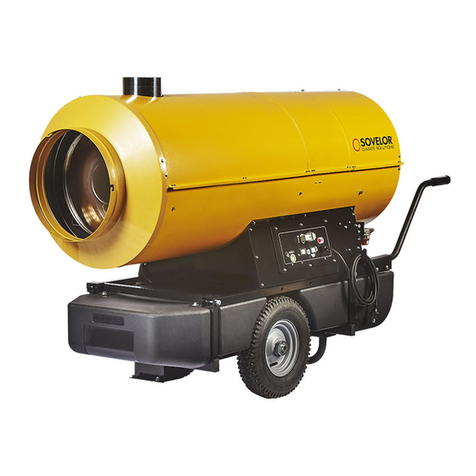
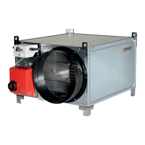
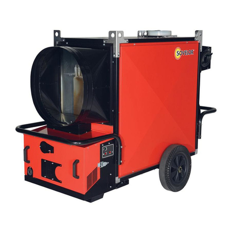
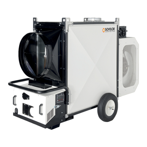
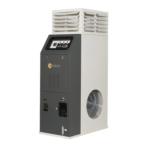
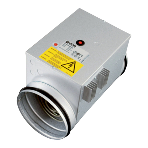
Sovelor ELITE C30 Manual

ELITE C30
86(5$1'0$,17(1$1&(%22.
en
0$18(/'ಬ87,/,6$7,21(7'(0$,17(1$1&(
fr

2
1LAMPE TEMOIN MISE SOUS TENSION
CONTROL LAMP
2COMMUTATEUR CHAUFFAGE - STOP - VENTILATION
CONTROL KNOB HEAT - STOP - VENTILATION ONLY
3CABLE ELECTRIQUE ALIMENTATION
POWER CORD
4THERMOSTAT VENTILATEUR, F
FAN THERMOSTAT, F
5THERMOSTAT DE SECURITE’ DE SURCHAUFFE, L1
OVERHEAT SAFETY THERMOSTAT, L1
6THERMOSTAT DE SECURITE A REARMEMENT MANUEL, L2
LIMIT THERMOSTAT WITH MANUAL RESTART, L2
7PORTE FUSIBLE POUR BRULEUR
BURNER FUSE HOLDER
8PRESSE ETOUPE POUR THERMOSTAT D’AMBIANCE
CABLE FASTENER FOR ROOM THERMOSTAT
9LAMPE TEMOIN SECURITE DE SURCHAUFFE, L1, L2
OVERHEAT THERMOSTATS CONTROL LAMP, L1, L2
10 LAMPE TEMOIN ARRET VENTILATEUR
FAN STOP CONTROL LAMP
11 REARMEMENT VENTILATEUR
FAN RESET
12 PRISE BRULEUR
BURNER PLUG
0
2
1
FL2 L1
2
9
11
12
7
1
8 11
6
5
4
3
CONSTRUCTEUR
MANUFACTURER
SOVELOR
Tel. 04 78.47.11.11
Fax 04 78.43.48.82
MODELES ELITE 30
MODEL
Avant d’utiliser le générateur, nous vous prions de lire attentivement toutes les instructions pour l’emploi, mentionnées ci après, et d’en suivre scrupu-
leusement les indications.
Le constructeur n’est pas responsable pour les dommages aux choses et/ou personnes dus à une utilisation impropre de l’appareil.
Before using the heater, read and understand all instructions and follow them carefully.
The manufacturer is not responsible for damages to goods or persons due to improper use of units.
Ed. 06/06
TABLEAU DE COMMANDE - CONTROL BOARD

DESCRIPTION
Le générateur d’air chaud ELITE 30 est destiné au chauffage de lo-
caux de moyennes ou de grandes dimensions qui imposent un système
de chauffage fixe.
L’air est chauffé grâce à l’énergie thermique développée pendant la
combustion et transmise par les fumées chaudes à l’air frais à travers
les superficies métalliques de la chambre de combustion, du type à
double tour de fumées, et à travers l’échangeur de chaleur.
Le conduit de passage de l’air et celui des fumées sont séparés et
ils sont réalisés avec des soudures et des joints à parfaite étanchéité.
Les produits de la combustion, après refroidissement, sont dirigés vers
un tuyau de décharge; ce tuyau doit être relié à une cheminée ou à un
conduit de fumées de dimensions suffisantes à garantir l’évacuation
des fumées.
L’air comburant, c’est à dire l’air nécessaire à la combustion, est
aspiré par le brûleur qui le prélève directement du milieu à chauffer; ce
milieu doit être bien aéré pour assurer un changement d’air suffisant.
Le générateur d’air chaud a deux vains (Fig.1): un antérieur conte-
nant le tableau de commende (a) et le brûleur (b) et un postérieur
contenant le réservoir (c) (seulement pour la version au fioul). Les deux
les vais sont accessibles en enlevant les panneaux (A) (exercer une lé-
gère traction sur la panneau).
Fig.1
Le générateur d’air chaud de la série peut-être utilisé avec des brû-
leur à fuel, a gaz naturel (G20) ou à G.P.L. (gaz propane G31 et gaz bu-
tane G30) ayant un système de fonctionnement ON-OFF.
Le générateur d’air chaud (Fig.2) a un gril d’aspiration de l’air et un
rideau d’envoyée de l’air (b), qu’ils doivent être mis toujours sur les cô-
tès des contraires. Le gril (a) et le rideau (b) peuvent être rangé indiffé-
remment sur un des deux côtés.
Fig.2
Attention
Seuls les brûleurs choisis et fournis par le constructeur
peuvent être utilisés. Le marquage CE déchoit si on sub-
stitue le brûleur avec un modèle non original, même si
ce dernier possède des caractéristiques similaires.
Enfin, le fonctionnement de l’appareil est contrôlé par trois disposi-
tifs de sécurité qui interviennent en cas de grave anomalie. Le coffret
de contrôle du brûleur, monté sur le châssis du brûleur-même et fourni
d’un bouton de réarmement, en provoque l’arrêt si la flamme s’éteint.
Le thermostat de sécurité à réarmement manuel, L, et le relais ther-
mique, RM, interviennent en arrêtant le fonctionnement du générateur.
Le thermostat intervient si la température de la chambre de combustion
dépasse la valeur limite présélectionnée (la lampe (8) s’allume). Le re-
lais thermique intervient si l’absorption de courant électrique du moteur
du ventilateur dépasse la valeur limite (la lampe (9) s’allume).
Si un de ces dispositifs intervient, il faut toujours chercher la cause
de cette intervention et l’éliminer avant de pousser le bouton de réar-
mement et faire démarrer le générateur (“ANOMALIES DE FONCTION-
NEMENT, CAUSES ET SOLUTIONS”).
RECOMMANDATIONS GENERALES
L’installation, le réglage et l’utilisation du générateur d’air chaud
doivent respecter les normes et les lois en vigueur relatives à l’utilisa-
tion de l’appareil.
Il convient de s’assurer que:
• les instructions contenues dans ce livret soient suivies scrupu-
leusement;
• le générateur ne soit pas installé dans des locaux ou il y aurait
des risques d’explosion ou d’incendie;
• des matériaux inflammables ne soient pas déposés à côté de
l’appareil (la distance minimun doit être d’au moins 3 m);
• des mesures suffisantes contre les incendies aient été prévues;
• l’aération du local dans lequel se trouve le générateur soit garan-
tie et suffisante aux nécessités de ce générateur;
• l’appareil soit placé à côté d’une cheminée et d’un tableau élec-
trique d’alimentation avec des caractéristiques conformes aux
caractéristiques déclarées;
• le générateur soit contrôlé avant sa mise en marche et régulière-
ment surveillé durant son utilisation; il faut éviter que des enfants
ou des animaux non surveillés s’approchent de l’appareil;
• à la fin de chaque période d’utilisation l’interrupteur de section-
nement soit débranché.
Il faut absolument respecter les conditions de fonctionnement du
générateur d’air chaud et en particulier:
• ne pas dépasser la puissance thermique maximum;
• s’assurer que le débit de l’air ne soit pas inférieur au débit nomi-
nal. Il faut donc contrôler qu’il n’y ait pas d’obstacles ou d’obs-
tructions aux conduites d’aspiration de l’air et/ou de sortie de
l’air, comme des toiles ou des couvertures placées sur l’appareil,
des murs ou des objets encombrants à côté du générateur, etc.
En effet, un faible débit d’air provoque la surchauffe de la
chambre de combustion et l’intervention du thermostat de sécu-
rité à réarmement manuel.
INSTRUCTIONS POUR L’INSTALLATION
Attention
Toutes les opérations décrites dans ce paragraphe doi-
vent être effectuées par le personnel spécialisé et auto-
risé à cet effet.
CONNEXIONS ELECTRIQUES ET REGLAGES
Le générateur d’air chaud est fourni avec tous les dispositifs de
contrôle et de sécurité indispensables au bon fonctionnement de l’ap-
pareil: un coffret électrique, un thermostat puor le ventilator et un ther-
mostat de sécurité à réarmememt manuel sont déjà branchés.
3
AA
c
ab
a
b
FR

Attention
La ligne électrique d’alimentation du générateur doit
être pourvue d’une mise à la terre et d’un interrupteur
magnéto- thermique avec un différentiel.
Le câble d’alimentation électrique doit être branché à un
tableau électrique muni d’un interrupteur de sectionne-
ment.
Il faut encore effectuer le branchement au réseau électrique. Cette
opération doit être effectuée avec un câble d’alimentation, après un
contrôle des caractéristiques de l’alimentation électrique qui se trou-
vent sur l’étiquette adésive.
Après avoir effectué toutes les opérations décrites et avant de
mettre en fonction la machine, il convient de contrôler les connexions
électriques effectuées avec celles reportées sur la schéma électrique et
de vérifier l’étalonnage du thermostat F (“LE TABLEAU DES CARACTÉ-
RISTIQUES TECHNIQUES”). Au premier démarrage il faut toujours
contrôler que l’absorption de courant du ventilateur ne dépasse pas
l’absorption déclarée.
RACCORDEMENT DU BRULEUR
Pour la version au fioul il n’est pas nécessaire faire des opérations
sur le brûleur car en celui-ci il est déja connecté soit à l’installation
électrique, soit au réservoir et il est réglé selon les indications du
constructeur.
Pour la version à gaz, par contre, le brûleur doit être monté sur le
générateur d’air chaud, uni à la ligne d’alimentation du combustible, uni
par la prise spéciale au tableau électrique et enfin il doit être réglé selon
les instructions reportées sur le manuel du brûleur en conformité aux
données techniques du générateur d’air chaud.
RACCORDEMENT AUX CONDUITS DE SORTIE DE L’AIR CHAUD
Le générateur d’air chaud est prévu pour fonctionner avec une dif-
fusion d’air chaud.
Ce dispositif peut être reliés à des conduits de section correcte, si
des exigences spécifiques d’utilisation le demandent; la valeur du débit
de l’air peut variée, pour ce motif il convient d’effectuer des contrôles et
des réglages. Ces contrôles et réglages sont absolument nécessaires
chaque fois qu’un changement significatif est apporté au circuit de dis-
tribution de l’air chaud (modifications de la longueur et du diamètre des
tubes, du nombre d’angles, etc.). Il faut:
• Vérifier que le courant absorbé par le moteur du ventilateur ne
soit pas supérieur à la valeur déclarée;
• Vérifier que le débit de l’air soit égal au débit nominal.
RACCORDEMENT AU CONDUIT D’EVACUATION DES FUMEES
Les conduites d’évacuation des fumées doivent être en acier et
conformes à la régle EN 1443.
Le rendement de la combustion et le fonctionnement correct du
brûleur dépendent du tirage de la cheminée. Le raccordement à la che-
minée doit être effectué en respectant les conditions des lois en vigueur
et en observant les prescriptions suivantes:
• le parcours du raccordement à la cheminée doit être le plus court
possible et en pente ascendante;
• il faut éviter les angles fermés ainsi que les réductions de section;
• il faut prévoir une cheminée pour chaque générateur;
• le tirage de la cheminée doit être au moins égal au tirage prescrit.
• le conduit de fumée doit avoir une longueur de 1 mètre.
ANALYSE DES PRODUITS DE LA COMBUSTION
Les sondes pour le contrôle des produits de la combustion et de la
température des fumées doivent être placées suivant les indications de
la Fig.3, en installant un conduit rectiligne muni de trou avec bouchon
pour prélèvement fumes.
Fig.3
BRANCHEMENT A LA LIGNE D’ALIMENTATION DU COMBUSTIBLE ET
PASSAGE D’UN TYPE DE GAZ A L’AUTRE
Ce branchement doit être exécuté en suivant les indications du livret
d’instructions du brûleur.
Le brûleur à gaz est du type polycombustible, il peut donc fonction-
ner avec du gaz naturel ou du G.P.L. Le générateur d’air chaud est four-
ni avec un brûleur déjà prédisposé pour fonctionner avec du gaz natu-
rel, G20. Pour le passage du gaz naturel au G.P.L. ou viceversa il faut
suivre les indications du livret d’instructions du brûleur. Ce livret est
joint au brûleur dans une enveloppe contenant l’éventuel orifice calibré
qu’il faut substituer (livret d’instructions du brûleur) et l’étiquette adhé-
sive indiquant le type de gaz pour lequel la machine est prédisposée.
INSTRUCTIONS POUR L’UTILISATION
DEMARRAGE
Pour mettre en marche le générateur:
• mettre le commutateur (2) sur la position “0”;
• alimenter électriquement le générateur en agissant sur l’interrupteur
de sectionnement placé sur le tableau électrique d’alimentation;
• si le fonctionnement est manuel, il faut déplacer le commutateur
(2) sur la position : le brûleur démarre et après quelques mi-
nutes de préchauffage de la chambre de combustion, le ventila-
teur démarre;
• si le fontionnement est automatique, il faut régler la valeur de la
température désirée sur le thermostat d’ambiance et placer le
commutateur (2) sur la position : le générateur démarre et
s’arrête automatiquement quand la température du local est res-
pectivement supérieure ou inférieure à la valeur sélectionnée;
• si après ces opérations le gènérateur ne fonctionne pas, il faut
consulter le paragraphe “ANOMALIES DE FONCTIONNEMENT
CAUSES ET SOLUTIONS” et découvrir la cause pour laquelle l’ap-
pareil ne fonctionne pas.
ARRET
Pour arrêter l’appareil il faut agir sur le commutateur (2), en le
mettant, sur la position “0” si le fonctionnement est manuel, ou sur le
thermostat d’ambiance si le fonctionnement est automatique. Le brû-
leur s’arrête et le ventilateur continue à fonctionner, en démarrant plu-
sieurs fois, jusqu’au refroidissement complet de la chambre de com-
bustion.
Attention
Il ne faut jamais arrêter le fontionnement du générateur
en débranchant l’interrupteur de sectionnement du ta-
bleau d’alimentation.
L’alimentation électrique doit être débranchée seule-
ment après l’arrêt du ventilateur.
VENTILATION
Pour obtenir la seule ventilation continue du générateur, il faut
mettre le commutateur (2) sur la position .
ENTRETIEN
Attention
Toutes les opérations décrites dans ce paragraphe doi-
vent être effectuées par le personnel spécialisé et auto-
risé à cet effet.
Pour un bon fonctionnement de l’appareil il est nécessaire d’effec-
tuer périodiquement les opérations suivantes. Avant de commencer, re-
tirez la prise électrique du générateur. Terminée tous les opérations
d’entretien, on doit remettre en service l’appareil, en vérifiant que
chaque fonction soit assurée.
Attention
Avant de commencer cette opération il faut:
• Arrêter l’appareil selon les indications du paragraphe
“ARRET”
• Débrancher l’alimentation électrique en agissant sur
l’interrupteur de sectionnement placé sur le tableau
électrique d’alimentation
• Attendre que le générateur se refroidisse
4
200 mm
FR

NETTOYAGE DE L’ECHANGEUR DE CHALEUR ET DE LA CHAMBRE DE
COMBUSTION
Pour prolonger la durée de la machine et en maintenir sa bonne ef-
ficacité, cette opération doit être effectuée au moins à la fin de chaque
saison de chauffe ou plus souvent s’il y a une présence excessive de
suie. Ce phénomème peut dépendre du tirage défectueux de la chemi-
née, de la mauvaise qualité du combustible, du mauvais réglage du
brûleur, de la succession plus ou moins fréquente des phases d’allu-
mage et d’arrêt du brûleur. Il est utile d’être attentif pendant le fonction-
nement: des pulsations au moment du démarrage peuvent être dues à
une présence excessive de suie.
Pour rejoindre la partie interne de la chambre de combustion et de
l’échangeur il faut d’abord enlever le brûleur (a), puis démonter le panel
postérieur (c) et celui d’inspection de l’échangeur (e) en enlevant les
turbolateurs (d): avec un écouvillon et un aspirateur enlever la suie et
les déchets.
Fig.4
NETTOYAGE DU VENTILATEUR
Il faut enlever d’éventuels déchets déposés sur la grille d’aspiration
(f), et si cela est nécessaire il faut nettoyer avec de l’air comprimé les
pales du ventilateur.
NETTOYAGE DU BRULEUR
Pour un bon fonctionnement du générateur il faut effectuer réguliè-
rement un entretien du brûleur en s’adressant à un centre d’assistance
technique autorisé.
Les opérations de nettoyage, entretien et réglage doivent de toutes
façons se dérouler en se conformant scrupuleusement aux instructions
spécifiques reportées sur le livret d’instructions.
Attenzione
Après chaque type de maintenance technique, vérifier
que l’appareille soit en fonction régulièrement.
TRANSPORT ET DEPLACEMENT
Pour le transport et le déplacement la machine doit être posée sur
une base et soulevée avec un chariot élévateur: aucun point d’accro-
chage n’a été prévu pour le soulèvement.
Attention
Avant de déplacer l’appareil il faut:
• Arrêter la machine selon les indications du paragraphe
“ARRET”
• Débrancher le courant électrique en enlevant la prise
• Attendre que le générateur se soit refroidi
Attention
N’essayer jamais de soulever manuellement le généra-
teur: son poids excessif pourrait vous provoquer des
dommages physiques importants.
e
a
f
b
c
d
5
FR

6
ANOMALIES DE FONCTIONNEMENT, CAUSES ET SOLUTIONS
ANOMALIE DE FONCTIONNEMENT CAUSE SOLUTION
• Vérifier le fonctionnement et laposition de
•l’interrupteur
• Vérifier les caractéristiques de laligne électrique
• Vérifier les branchements électri-ques
• Vèrifier l’efficacité des fusibles
• Mauvaise position de l’interrup-teur général • Sélectionner laposition correcte
• Vérifier laposition du thermostat et lacorriger
• Vérifier le bon fonctionnement du thermostat
• Dispositif de sécurité (brûleur, thermostat L,
•relais thermique) non réarmé après une
•réparation • Pousser le respectif bouton de réarmement
• Contrôler le dèbit du combustible
• Vérifier lacorrecte position d’é-ventuels
•rideaux, gâches, etc.
• Enlever d’éventuels déchets blo-qués dans les
•conduites de l’air ou dans les grilles de
•ventilation.
• Régler le raport de transmission entre le moteur
•et le ventilateur
• Intervention du relais thermique RM
•(lalampe (9) s’allume) • Absorption excessive de courant du moteur du
•ventilateur • Régler le rapport de transmission entre le
•moteur et le ventilateur.
• Le brûleur démarre, laflamme ne s’allume pas,
•lalampe témoin du bouton de réarmement
•s’allume • Mauvais fonctionnement du brûleur
• Si après avoir poussé le bouton de rèarmement
•et après avoir fait démarré le générateur,
•l’inconvé-nient se répète pour une seconde fois,
•il faut s’dresser au Service d’Assistance Tecnique
• Vérifier l’efficacité des fusibles
• Vérifier les branchements électri-ques
• Panne du thermostat F • Contrôler le thermostat, le régler et
•éventuellement le remplacer
• Bobinnage du moteur brûlé ou interrompu • Remplacer le moteur du ventila-teur
• Condensateur du moteur brûlé • Remplacer le condensateur
• Roulements du moteur bloqués • Remplacer les roulements
• Déchets déposés sur les pales du ventilateur • Enlever les déchets
• Circulation de l’air insuffisante • Eliminer tout obstacle possible au passage de
•l’air
• Lacourroie de transmission desserrée ou non
•alignée • Régler latension de lacourroie de
•transmission.
• Réchauffement insuffisant • Capacité du brûleur insuffisante • S’adresser au Service d’Assistance Technique
• Bruits et vibrations du ventilateur
• L’appareil ne démarre pas
• Le courant électrique n’arrive pas
• Mauvais fonctionnement du ther-mostat
•d’ambiance
• Le ventilateur ne démarre pas ou démarre en
•retard
• Le courant électrique n’arrive pas
• Intervention du thermostat L
•(lalampe (8) s’allume) • Surchauffe de lachambre de combustion
FR

7
DESCRIPTION
ELITE 30 space heater has been designed for use in small to medi-
um-sized rooms and buildings where a fixed heating system is re-
quired.
Heat is produced by combustion and the heat from the smoke is
transmitted to the fresh air through the metal walls of the combustion
chamber and the heat exchanger. The combustion chamber is of the
type where smoke circulates twice.
The air and smoke pass through separated ducts, both of which
are welded and sealed. When, after combustion, the waste gases have
cooled, they are expelled through a duct which must be connected to a
chimney or chimney flue. The chimney or chimney flue must be big
enough to guarantee that the smoke is expelled efficiently.
The air which is used in combustion is aspirated directly from the
room or building which is being heated. It is therefore of utmost im-
portance that the room or building be properly ventilated so that
enough fresh air is circulating at all times.
The space heater is equipped with two vain (Fig.1): a front one in-
cludes the control panel (a) and the burner (b), and a back one includes
the tank (c) (only for oil version). Both compartments are accessible
removing the panels (A) (practice a light traction on the panel).
Fig.1
ELITE 30 space heater can operate with burners that are fuelled by
heating oil, methane (G20) or L.P.G. (butane G30 and propane G31) of
the ON-OFF type.
The space heater (Fig.2) is equipped with air suction grate (a) and
a heat output shutter (b), that always have to be placed on opposite
sides. The air suction grate (a) and the heat output shutter (b) can be
placed indifferently on one of the two sides.
Fig.2
Warning
Only the burners which are chosen and supplied by the
manufacturer can be used. If another type of burner is
used the heater no longer complies with CE regulations.
There are three safety devices which are activated in case of serious
malfunction. The Burner Control Device, which is mounted on the
burner and has a restart button, automatically stops the burner if the
flame goes out. The Overheat Thermostat, L, of the manual restart
type, is activated if the temperature of the combustion chamber rises
above the set maximum limit; the warning light (8) lights up and the
heater stops working. The Thermal Relay, RM, is activated if the fan
motor starts to useelectrical current than the maximum permitted limit;
the warning light (9) lights up and the heater stops working.
If any of these safety devices are activated you should check careful-
ly what the problem actually is before pressing the restart button and
starting the heater off again (“OBSERVED FAULTS, CAUSES AND
REMEDIES”).
GENERAL ADVICE
The space heater must be installed, set up and used in accordance
with existing laws. Here are a few general guidelines which should be
followed:
• Follow the instructions in this booklet very carefully;
• Don’t install the heater in places where there may be a risk of fire
or explosion;
• Inflammable material should be kept at a safe distance from the
heater (minimum 3 meters);
• All fire prevention regulations must be adhered to;
• The room or building which is being heated must be sufficiently
ventilated so that the heater has enough air to function properly;
• The heater must be near a chimney or chimney flue and a suitable
electric switchboard;
• Don’t let animals or children near the heater;
• After use make sure the disconnecting switch is off;
When using any type of space heater it is obligatory:
• not to exceed the maximum level of heat output of the furnace.
• to make sure that there is adequate air circulation and air supply to the
heater and that nothing is obstructing the aspiration and expulsion of
air. Movement of air may be obstructed in various ways including plac-
ing covers or other objects on the heater or positioning the heater too
near a wall or other large object. If there is insufficient air supply the
combustion chamber overheats and the overheat thermostat with man-
ual restart is activated.
INSTALLATION
Warning
The following operations must be carried out by quali-
fied personnel only.
ELECTRICAL CONNECTIONS AND SETTINGS
Every space heater is supplied along with the safety and control
devices which are indispensable to the correct functioning of the unit.
The electric switchboard, the fan thermostat and the overheat thermo-
stat with manual restart have already been connected.
Warning
The mains supply to the heater must be earthed and
have a magneto-thermal switch with differential.
The power cord must be connected to a switch board
which has a disconnecting switch.
You still must connect the power cord having read the adhesive la-
bel which details electricity supply characteristics.
Having completed all these operations check carefully that all elec-
trical connections correspond to the wiring diagram and check the set-
ting of thermostat F (“TECNICAL SPECIFICATION”). When the heater is
first turned on you must check that the fan does not use more current
than the maximum permitted limit.
AA
c
ab
a
b
GB

8
CONNECTION OF THE BURNER
For the oil version is not necessary to do some operation on the
burner since it is already connected to the electric system, both to the
tank and it is regulated according to the indications of the builder.
For the gas version, on the contrary, the burner has to be assem-
bled on the space heater, connected to the fuel feeding line and
through the special taking to the electric panel and finally has to be
regulated following the instructions on the burner manual unanimously
to the technical data pointed for the space heater.
CONNECTION TO HOT AIR DUCTS
The space heater provides heat by releasing and dispersing hot air.
An air head is supplied with each unit and it can be connected to
new air ducts if the user wishes to satisfy specific needs. In this case
and in particular if the diameter and length of the ducts have been
changed or if the number of bends has been modified, air output may
vary. Consequently it is very important to check and regulate air output
when any modification is made to air heads or air ducts. In all circum-
stances you must ensure that:
• The fan motor does not absorb more current than the maximum
permitted limit.
• The volume of air flow corresponds to the recommended level.
DRAFT
The evacuation smoke flues have to be in steel and conforming to
the norm EN 1443.
Efficient combustion and trouble-free working of the burner de-
pend on efficient flue draft. The unit must be connected to the chimney
flue in accordance with current legal regulations and in line with the
following guidelines:
• the tube which carries the smoke should cover as short a dis-
tance as possible and should slant upwards;
• there should be no sharp bends in the tubes and the diameter of
the tubes must never be reduced;
• every heater must have its own chimney;
• flue draft must at least correspond to the minimum compulsory
level in the Technical Specifications;
• the chimney flue has to have a length of 1 meter.
ANALYSIS OF COMBUSTION WASTE PRODUCTS
The probes which check the composition of combustion waste
products and smoke temperature must be positioned as indicated in
Fig.3, installing a rectilinear duct provided of hole with plug for collect-
ing smokes.
Fig.3
CONNECTION TO FUEL SUPPLY AND CHANGING FROM ONE TYPE OF
GAS TO ANOTHER
To connect the burner to the fuel supply, follow the instructions in
the Burner Instruction Manual.
The burner can use both methane gas and L.P.G. This heater has
been predisposed to use methane gas, G20. To change from methane
gas to L.P.G. or vice versa consult the Burner Instruction Manual
which accompanies this manual. With the Burner Instruction Manual
there is an envelope, which contains a spare choke and an adhesive la-
bel that indicates the type of gas that the burner should use.
INSTRUCTIONS FOR USE
SWITCHING ON
• Set the control knob (2) in position “0”.
• Turn on the disconnecting switch on the electric switchboard.
• If the unit is operated manually turn the control knob to . The
burner starts up, the combustion chamber heats up and then the
fan starts.
• If the unit operates automatically set the room thermostat at the
desired level and turn the control knob (2) to : the heater will
now start and stop automatically.
• If the heater doesn’t start after you have completed the above
operations consult the Troubleshooting section of this manual.
TURNING OFF
In manual operation turn control knob (2) to “0” or turn off control
in automatic operation.
The burner stops while the fan turns itself on and off until the
combustion chamber has completely cooled down.
Warning
Never stop the heater by simply turning off the discon-
necting switch on the electric switchboard. The electri-
cal supply must only be disconnected when the fan has
come to a complete stop.
VENTILATION
When the control knob is turned to the symbol the heater oper-
ates in continuous fan mode.
MAINTENANCE
Warning
The following operations must be carried out by quali-
fied personnel only.
Finished all operation of maintenance, you have to restart the ma-
chine, verifying that every function is insured.
Warning
Before carrying out any maintenance operation the
heater must be disconnected from the mains. Therefore:
• Stop the machine as instructed above
• Turn off the disconnecting switch on the electric
switchboard
• Wait until the heater has cooled
Cleaning the heat exchanger and the combustion chamber.
For the heater to operate efficiently the heat exchanger and com-
bustion chamber must be cleaned after a period of prolonged use and
more frequently if too much soot builds up. Soot builds up when there
is not enough chimney draft, when the fuel is of very poor quality,
when the burner is regulated incorrrectly or when the heater is
switched on and off too frequently. If the heater starts vibrating when it
is turned on there is probably too much soot.
To reach the internal part of the heat exchanger and the combus-
tion chamber remove the burner (a) and the back panel (c) as well as
the exchanger inspection panel (e) and the baffle plates (d): Remove
soot and extraneous material with a vacuum cleaner or tube cleaner.
Fig.4
CLEANING THE FAN
Remove any dirt or extraneous material from the mesh of the aspi-
ration grill (f) and if necessary clean the propeller with an air-suction
tool.
200 mm
e
a
f
b
c
d
GB

9
CLEANING THE BURNER
For the heater to work efficiently the burner must be serviced reg-
ularly by an Authorized Service Technician. All cleaning,servicing and
regulation operations must be carried out as indicated in the Burner In-
struction Manual.
Warning
After every type of technical maintenance, please verify
that the machine starting regularly.
TRANSPORTING AND MOVING THE HEATER
To move or transport the heater place it on a raised base and then
lift with a forklift truck. There are no eyebolts or other hooking points.
Warning
Before moving a unit:
• Turn it off as indicated above
• Disconnect electricity by pulling out the plug
• Wait until the heater cools down
Warning
Never try to lift the heater manually. Doing so could re-
sult in physical injury.
GB

10
OBSERVED FAULTS, CAUSES AND REMEDIES
OBSERVED FAULT CAUSE REMEDY
• Check function and positioning of main switch
• Check power cord
• Check electrical connections
• Check fuses
• Wrong positioning of main switch • Put main switch in correct position
• Check setting of room thermostat
• Check function of room thermo-stat
• Safety device (burner, thermostat L, Thermal
•relay) not restarted after repairs • Press the appropriate restart button
• Check fuel flow
• Check position registers, draw-holes, etc.
• Remove extraneous material from air ducts and
•ventilation grills
• Increase air flow adjusting transmission
•between motor and fan
• Thermal relay RM cuts in (warning light (9)
•lights up) • Fan current absorption is excessive • Adjust transmission between motor and fan
• The burner starts up, the flame doesn’t light up
•and the restart light comes on • Burner not working correctly • Press the restart button to turn on the heater. If
•the same problem arises again call an
•Authorized Service Technician
• Check fuses
• Check electrical connections
• F thermostat out of order • Check the thermostat, set it and replace it if
•necessary
• Winding of motor burnt or interrupted • Replace the fan motor
• Condenser burnt • Replace the condenser
• Motor bearings blocked • Replace the bearings
• Extraneous material on fan blades • Remove extraneous material
• Not enough air circulation • Remove obstacles to air circulation
• Drive belt loose or not aligned • Adjust drive belt tension
• Not enough heat • Wrong burner • Call an Authorized Service Technician
• The combustion chamber has overheated
• Thermostat L cuts in
•(warning light (8) lights up)
• No electrical power
• The fan doesn’t start up or starts up late
• The fan vibrates or makes unusual noise
• Wrong setting of room thermostat
• Faulty electrical supply
• The heater won’t start
GB

FTHERMOSTAT VENTILATEUR, F
FAN THERMOSTAT, F
FB
FUSIBLE BRULEUR 6A
BURNER FUSE 6A
TM
TELERUPTEUR VENTILATEUR
FANS TELE-CONTACTOR
RM
RELAIS THERMIQUE DES VENTILATEUR
FANS THERMAL RELAY
ST
LAMPE TEMOIN MISE SOUS TENSION
CONTROL LAMP
SB
LAMPE TEMOIN ARRET VENTILATEUR
FAN STOP CONTROL LAMP
BR
BRULEUR
BURNER
TA
THERMOSTAT D’AMBIANCE
ROOM THERMOSTAT
PB
PRISE BRULEUR
BURNER
L1
THERMOSTAT DE SECURITE DE SURCHAUFFE, L1
OVERHEAT SAFETY THERMOSTAT, L1
L2
THERMOSTAT DE SECURITE A REARMEMENT MANUEL, L2
LIMIT THERMOSTAT WITH MANUAL RESTART, L2
R9
COMMUTATEUR CHAUFFAGE-STOP-VENTILATION
CONTROL KNOB HEAT-STOP-VENTILATION ONLY
SL
LAMPE TEMOIN SECURITE DE SURCHAUFFE, L1, L2
OVERHEAT THERMOSTATS CONTROL LAMP, L1, L2
PA
PRISE THERMOSTAT D’AMBIANCE
ROOM THERMOSTAT PLUG
SCHEMA ELECTRIQUE - WIRING DIAGRAM
M
MOTEUR VENTILATEUR
FAN MOTOR
C
CONDENSATEUR
CONDENSER
&
&211(;,21',5(&7(0(77(855(&(37(85
IDLUHEDVFXOHPHQWVURWDWLIUDSLGHVXUOHWKHUPRVWDW
OD/('GHOHPHWWHXUGDQVOHWKHUPRVWDWVHPHWDORUVDFOLJQRWHUUDSLGHPHQWSHQGDQWVHFRQGHV
LQGLTXDQWDLQVLODWWHQWHGHFRQQH[LRQ
3HQGDQWTXHOD/('GHOHPHWWHXUFOLJQRWWHIDLUHXQDSSXLFRXUWDYHFXQRXWLOLVROpVXUOHERXWRQ
FRQQHFWGXUHFHSWHXUGDQVOHWDEOHDXpOpFWULTXHOD/('GHOHPHWWHXUVDUUHWHGHFOLJQRWHU
$77(17,21/(*(1(5$7(85'2,7(75(62867(16,21
VLODFRPPDQGHHVWLQYHUVpHPLVHHQURXWHGHODSSDUHLOTXDQGOHWKHUPRVWDWWHQGYHUV]HUR
0HWWUHOHWKHUPRVWDWDXPLQLPXP&RXSHUODOLPHQWDWLRQVHWUHEUDQFKHU

Hi [kcal/h]
[kW]
[m3/h]
[kcal/h]
[kW]
[°C]
[°C]
[V]
[Hz]
Gsl G20 G30 G31
[kg/h] 2,93 - 2,74 2,70
[Nm3/h] ** - 3,49 - -
[mbar] - 202937
[mm]
øxL [mm]
[dm3]
[Nm3/h]
[W]
[W]
[mm H2O]
[mbar]
[mbar]
[mm]
[mm]
[°C]
[°C]
[dBA]
Minima [°C]
Massima [°C]
[mm]
[kg]
* Avec brûleur Ecoflam - With Ecoflam burner
** 15 °C - 1013,25 mbar
Attention: Pour le type de gaz utilisé voir la prédisposition du brûleur d'air soufflé
Note: For the type of used gas to see the predisposition of the air burner blown
Poids
Weight
Contre pression fumées *
Burned gases pressure *
Température limite de sécurité
Safety limit temperature setting
Température démarrage ventilateur
Fan starting temperature
Niveau sonore à 1 m *
Noise level at 1 m *
Dimensions, L x P x H *
Dimensions, L x W x H *
Tirage minimum nécessaire *
Compulsory flue draft *
Diamètre sortie fumèes
Flue diameter
Sortie air
Air outlet
Température d'exercice
Temperature of exercise
CARACTERISTIQUES TECHNIQUES
TECHNICAL SPECIFICATIONS
Pression gaz
Gas pressure
Consommation
Consumption
Combustible
Fuel
Puissance thermique max
Max heating output
Débit d'air
Air output
Puissance thermique nette *
Net heating output *
Alimentatione électrique
Power supply
Phase
Phase
Tension
Voltage
Fréquence
Frequency
Pression statique disponible
Available static pressure
Puissance électrique ventilateur
Fan power consumption
Chambre de combustión
Combustion chamber
Pénétration du
brûleur
Penetration burner
Dimensions
Dimensions
Volume
Volume
Débit des fumées *
Smokes flow *
Puissance électrique *
Total power consumption *
180
29.900
34
,
8
2.100
26.060
30
,
3
1
230
50
1
70
64,9
1355 x 560 x 1370
35
90
0,1
150
617 x 249
-20
50
514
677
5
ELITE 30
350 x 470
30
66,16
Protection IP
IP protection IP 20
Bruleur Gaz
Burner Gas
Ecoflam
AZUR 40 TC
Température min. de service
Min. service temperature -5
Type
Type B23
Température max. de service
Max. service temperature 40
CARATERISTIQUES TECNIQUES - TECHNICAL SPECIFICATIONS

ELITE 30
Ed. 06/06
B
A C
35 36
38
34
33
32 37
01
06
04
03
05
02
31
26
19
30
09
10
07
08
05
11
12
13 14 15
18 19
23
27
28
29
25 22
20
21
06
42 41
32
39 40
D
E
F
F
16
17
D
E
A
B
24
30
F

66
Ed. 06/06
Filtro Gasolio - Filtre - Filter - Filter OPTIONAL
46
48
47
57
56
51 55
54
53
50
44
45
43
51
49
41
75
82
76
77
78
79
80
73
74
81
83
84
85
71
68
70
69
67
72
51
09
63
64 65
60 59
61
62
51
HG
58
41

ELITE 30 06-06
Pos. Cod. LÉGENDE Pos. Cod. LÉGENDE Pos. Cod. LÉGENDE
1G05095 Panneau latéral antérieur 33 I20409 Raccord droit 1/4" Mx8 66 G04014 Chambre de combustion
2G05096 Panneau sortie air 34 I31018 Bouchon PL réservoir 67 I25001 Bouchon
3T40257 Coffre diffuseur air 35 M20404 Ressort 68 G05121 étrier blocage turbulateur
4G05097 Panneau de sortie air 36 M20406 Tourillon pour ressort 69 T10669 Joint isolant 513x248x5
5G05098 Support sortie air 37 M20301 Rondelle élastique Ø4 70 G05122 Porte visite cheminée
6G05099 Panneau frontal 38 M10702 Ecrou M4 71 G01850 Turbulateur
7G01098 Support brûleur 39 M10531 Capuchon vis 72 M10511 Vis TE AF14x5/8”
8T10602 Joint de bride 210x210x5 40 M10507 Vis TC 8x1" 1/2 73 T20201 Filtre 1/4"
9G05100 Support bulbe thermostat 41 I20410 Raccord 90°1/4” Mx8 74 T20205 Couvercle filtre 1/4"
10 G05101 Support coffret de commande 42 M20418 Serrure Ø22 75 T20202 OR du filtre
11 G05102 Support brûleur 43 E20640 Fiche thermostat 3P + T 76 T20214 Joint supérieur
12 G05103 Protection couvercle 44 M10514 Vis TC 4x1/2" 77 T20206 Cartouche filtre
13 G05104 Couvercle 45 E20627 Plaque de prise 3P + T 78 T20213 Joint inférieur
14 G05105 Panneau latéral antérieur 46 E11021 Lampe témoin rouge Ø12 V230 79 T20212 Cuve filtre
15 G05106 Plaque de centrage 47 E10109 Commutateur 1-0-2 80 T20234 KIT OR
16 G05107 Cheminée 48 E10302 Fusible A 6 81 T20236 Support
17 G05108 Bride cheminée 49 E20506 Porte fusible 82 M10509 Vis TE14x1/2" FR
18 G05109 Panneau latéral supérieur 50 E20707-49 Coffret électrique 83 02AC282 Cheminée Ø150mm Inox
19 G05110 Panneau latéral postérieur 51 E20918 Presse câble PG 9 84 02AC379 Raccord Ø150mm Inox
20 G05111 Porte visite 52 E20301 Barrette de connections 12 el. mmq 10 85 02AC378 Tuyau fumée Ø150mm Inox
21 G05112 Réservoir 54 G04042 Plaque support
22 G05113 Support réservoir 55 E10418 Contacter Wimex KN16 V220 G + H G00139 Coffret électrique
23 G05114 Protection support réservoir 56 E20913 Presse câble PG 11
24 G05115 Protection latéral supérieur 57 E11134 Relais Iskra TRB14 A. 2,4 - 4
25 AN012 Ventilateur DDM 10/8 IP55 58 E30442 Câble électrique
26 G05116 Fond 59 E20719-03 Coffret électrique
27 G05117 Support ventilateur centrifuge 60 E50747 Thermostat TY95 20/60 °C Campini
28 G05092 Panneau aspiration air 61 P30163 Porte-bulbes
29 G05124 Protection 62 C30712 Collier
30 G05119 Protection latéral inférieur 63 E50748 Thermostat TY95 50/90 °C Campini
31 G05120 Panneau latéral inférieur 64 E50750 Protection pour thermostat de sécurité
32 I40306 Tuyau Rilsan Ø8x6 65 E50749 Thermostat TY95H 120 °C Campini

Dantherm S.p.A.
Via Gardesana 11, -37010-
Pastrengo (VR), ITALY
Dantherm S.p.A.
ȼɢɚȽɚɪɞɟɫɚɧɚ11, 37010
ɉɚɫɬɪɟɧɝɨȼɟɪɨɧɚɂɌȺɅɂə
Dantherm Sp. z o.o.
ul. Magazynowa 5A,
*ąGNL32/$1'
Dantherm Sp. z o.o.
ɭɥɆɚɝɚɡɢɧɨɜɚ$
62-023 ȽɚɞɤɢɉɈɅɖɒȺ
Dantherm SAS
9(1,66,(8;&HGH[)5$1&(
Dantherm SAS
23 ɭɥȿɜɝɟɧɢɹɏɟɧɚɮɮɚ±ɐɋ
ȼȿɇɂɋɖȿɐɟɞɟɤɫɎɊȺɇɐɂə
Dantherm LLC
ul. Transportnaya 22/2,
6783,120RVFRZUHJLRQ5866,$
ɈɈɈ©Ⱦɚɧɬɟɪɦª
ɍɥɌɪɚɧɫɩɨɪɬɧɚɹ
ɝɋɬɭɩɢɧɨɆɨɫɤɨɜɫɤɚɹɨɛɥɊɎ
Dantherm China LTD
8QLW% YXQFKXDQ5G
6KDQJKDL&+,1$
Dantherm China LTD
ɘɧɶɱɭɚɧɶɪɨɚɞɫɬɪɨɟɧɢɟȼ
ɒɚɧɯɚɣɄɂɌȺɃ
Dantherm SP S.A.
&&DODER]RV3ROtJRQR,QGXVWULDO
$OFREHQGDV0DGULG6P$,1
Dantherm SP S.A.
ɐɄɚɥɚɛɨɡɨɫɉɨɥɢɝɨɧɨɂɧɞɭɫɬɪɢɚɥ
ȺɥɤɨɛɟɧɞɚɫɆɚɞɪɢɬɂɋɉȺɇɂə
This manual suits for next models
3
Table of contents
Languages:
Other Sovelor Heater manuals
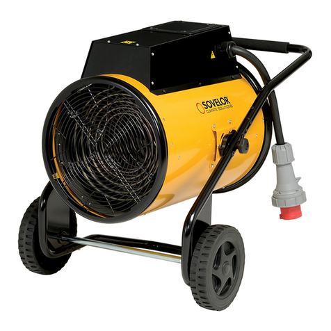
Sovelor
Sovelor C40G Manual
Sovelor
Sovelor MINISUN DC Manual
Sovelor
Sovelor HP30 User manual
Sovelor
Sovelor GP 35 User manual
Sovelor
Sovelor GA/N45C Operating instructions
Sovelor
Sovelor HP30 User manual

Sovelor
Sovelor TITAN GAZ Manual
Sovelor
Sovelor F35 User manual
Sovelor
Sovelor MASTER CED2 Manual
Sovelor
Sovelor CYNOX50F Manual
Popular Heater manuals by other brands

Vaillant
Vaillant uniSTOR VIH GB 260 S Instructions for and... Instructions for installation
DeLonghi
DeLonghi TRD40615ECA Instructions for use
VOLTOMAT HEATING
VOLTOMAT HEATING FH-110692.1 instruction manual

Sealey
Sealey ABI1000 manual
TREVIDEA
TREVIDEA G3Ferrari G60008 user manual

Sure Flame
Sure Flame ID400 Operation and maintenance manual

