SP PARTNERS Rainbow Attic Stair Galaxy G2755 User manual
www.RainbowAtticStair.com
By SP Partners, LLC
INSTALLATION GUIDE
Galaxy

IMPORTANT
READ THIS FIRST
●Inspect stair for any damage prior to installation.
●Stair is NOT to be installed while home is under construction and
used as a construction stair.
●The correct number of treads for floor-to-ceiling height MUST be
attached. The stair may have had one of the 3 extra steps pre-
installed at the factory. To determine the correct number of treads
that should be installed for your height, refer to Table A on page 3.
Do not add or remove treads solely for changing the angle of the stair.
This will cause an unsafe condition and damage the stair.
●Adjustment Screw on stabilizer arm MUST be set before climbing
stair. This adjustment provides structural support necessary for
use. See page 7.
Failure to follow any or all of these
guidelines can result in damage to
the stair and will void the warranty.
If you have any problems or concerns with stair,
call SP Partners LLC immediately at 877-369-6996
Page 1 July 2014
Drill, tape measure, 1/4” wood drill bit, hammer, crescent wrench, wood shims, ladder, lumber
with same dimensions as joists, keyhole saw or utility knife to cut ceiling material.
Page 2 July 2014
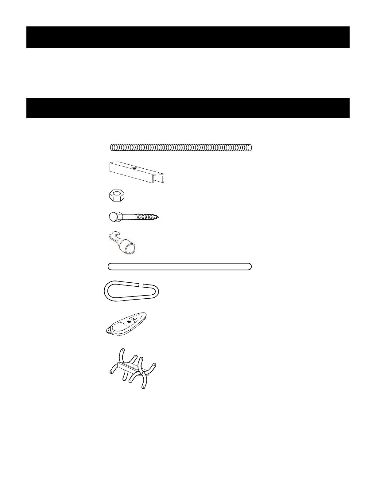
Parts Included
Tools / Materials Required
(4) 3/8” Threaded Rod
(4) Joist Hanger
(8) 3/8” Hex Nut
(10) 3” Lag Screw
(1) Door Hook
(1) Wood Dowel
(1) Door Opening Ring
(3) Extra Steps
Remote Control

Determine whether the chosen location allows sufficient “projection” and “landing space” for your unit. See
TABLE A above and Figure 1 below.
Figure 1
Locating the Stair
This stairway is for residential use only.
Maximum capacity is 350 lbs.
Installer should be experienced in the construction or modification of structural framing
supports. Improper installation can result in stair collapse and bodily injury.
Determine location of electrical lines or plumbing before cutting ceiling.
WARNING
Page 3 July 2014
Table A
MODEL # COLOR ROUGH
OPENING SIZE FRAME
DIMENSIONS TREAD
WIDTH FLOOR TO CEILING
HEIGHT RANGE NUMBER OF
STEPS PROJECTION LANDING
SPACE
G2755 - as assembled GRAY 27 3/4” X 55 1/4” 27 1/4” X 54 3/4” 14” 7’-2” to 7’ - 10” 9 6” 51”
- Add one step Over 7’ - 10” to 8’ - 6” 10 11” 56”
- Add two steps Over 8’ - 6” to 9’ - 6” 11 15” 61”
- Add three steps Over 9’ - 6” to 10’ - 2” 12 20” 65”
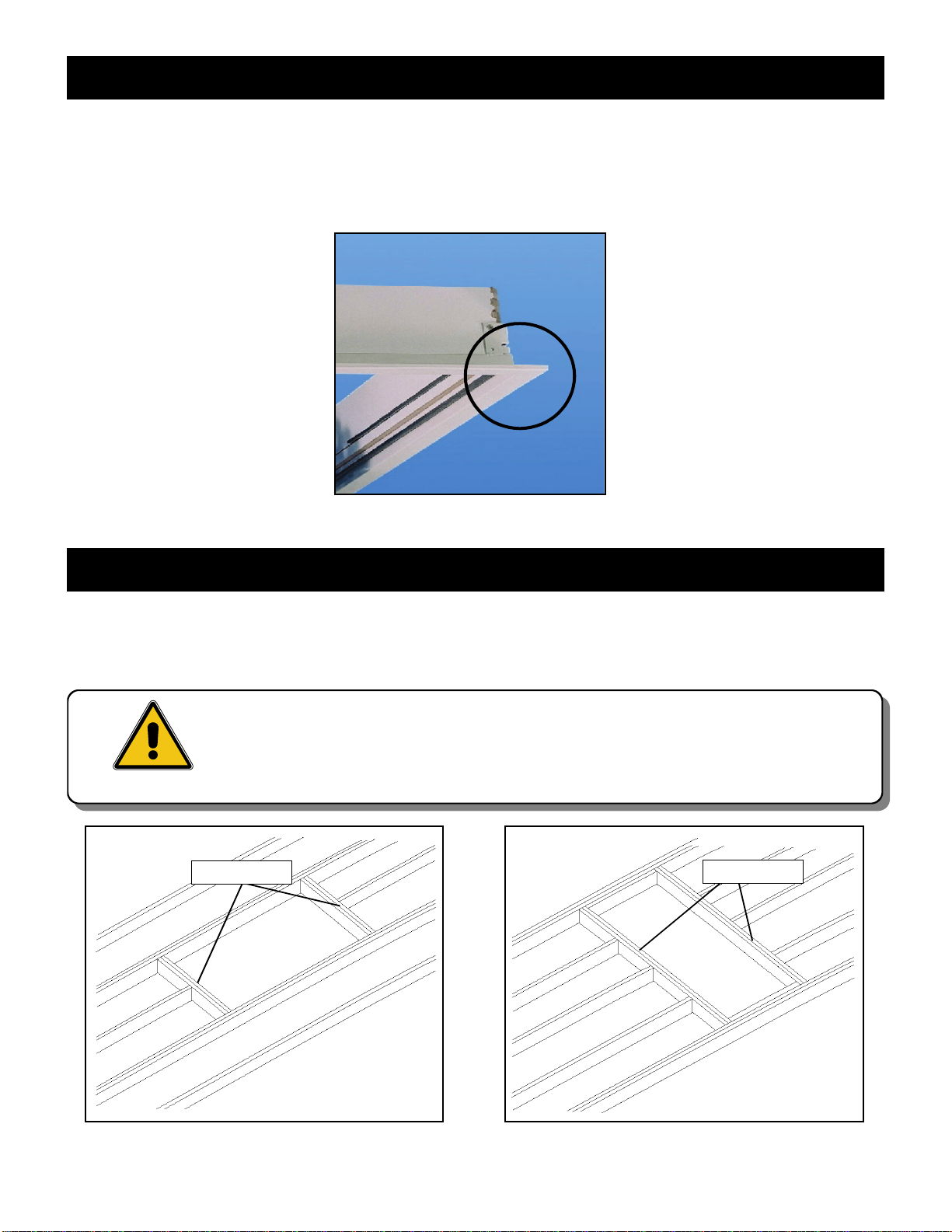
1. Mark out the rough opening size for your unit according to TABLE A. Note that the finished metal
trim extends about 2” beyond the rough opening when the unit is installed (Figure 2). Allow
clearance for this on all four sides.
2. Cut the rough opening through the ceiling material.
Figure 2
Preparing the Opening
Most attic stairs will be installed parallel to the ceiling joists (Figure 3). In cases where they are installed
perpendicular to joists (Figure 4), some joists will need to be cut and tied-in to other joists with “headers”
of the same dimensions as the joists and will form the box frame into which the stair will be secured.
Before cutting any joists, watch out for electrical wiring.
If your attic is constructed using trusses, DO NOT CUT CEILING JOISTS WITH-
OUT CONSULTING AN ENGINEER AND OBTAINING APPROVAL.
WARNING
Framing the Opening
Page 4 July 2014
Figure 3 Figure 4
HEADERS
HEADERS
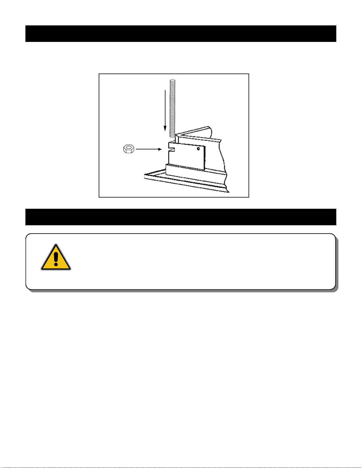
Insert hex nuts provided into slot in metal frame corner and insert threaded rod into channel. Thread rod
into nut as far as possible. Repeat process for all corners. See Figure 5.
Figure 5
Preparing the Stair
Page 5 July 2014
1. Person in attic should have the four joist hangers and hex nuts ready.
2. Have two additional helpers below lift the stair straight up into the framed opening until the tops of the
threaded rods clear the top of the frame opening headers.
3. Starting at one end, slide a joist hanger onto the threaded rod and thread nut down until there is only
about 1/2” slack. Do not tighten fully. Turn joist hanger at a 45 degree angle to span the frame cor-
ner. Figure 6. Repeat the process until all hangers are installed. With hangers holding stair in place,
helpers can let go.
4. Square stair to frame. Try to maintain an even gap all around between stair and headers.
5. Tighten nuts in stages all around. Do not over-tighten as this may distort metal trim on ceiling side.
6. Attach door opening hook to wood dowel using (2) 1/2” wood screws. Figure 7.
7. Door can now be opened but DO NOT EXTEND OR STAND ON STAIR YET.
Note: Rainbow “Galaxy” stairs are designed to be installed with both steel joist
hangers and lag bolts. Do not install with lag bolts alone.
Be sure that there is adequate light in the attic since the stair will block
any light from the room below when raised into place.
Make sure door is closed and latch is engaged
DUE TO ITS WEIGHT, TWO ADDITIONAL HELPERS MUST BE USED TO
SAFELY RAISE STAIR INTO OPENING AND HELD FOR A FEW MOMENTS
UNTIL TEMPORARILY ANCHORED BY INSTALLER ABOVE.
WARNING
Installing the Stair

Figure 6
HEADERS
1/2” SLACK
Figure 7
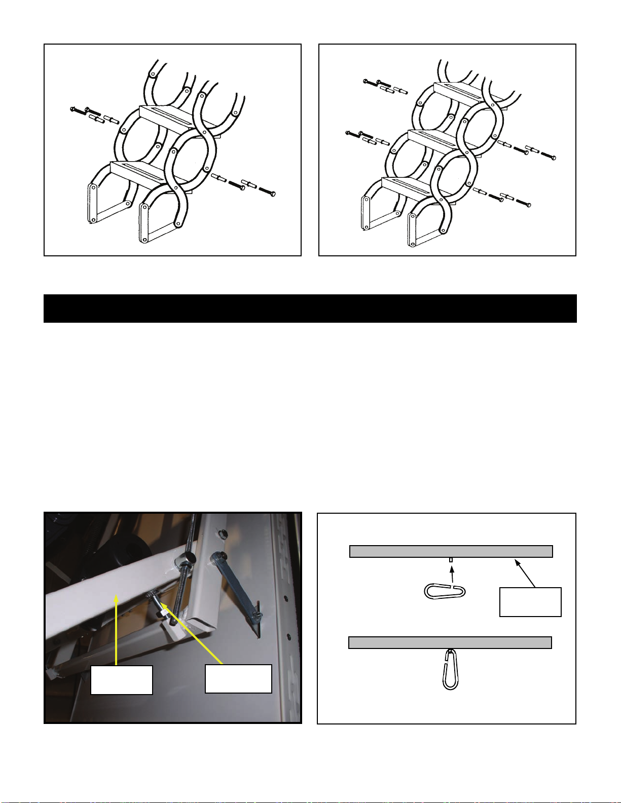
Adding Treads
Determine the correct number of steps required for your floor-to-ceiling height (See Table A on page 3).
Make sure the unit is plugged into a power supply. If no additional steps are needed, skip this section.
1. Lower stair and stop to within two feet of the floor to allow space for added treads. Remove bottom
tread of unit by removing the four bolts, washers and sleeves. Figure 9. This will be reattached at the
end.
2. Add one or both treads as required by reinserting sleeves, washers and bolts. Figure 10. (Additional
hardware is provided with extra treads).
3. Re-attach bottom tread.
Page 6 July 2014
There are two buttons on the remote. The center button
will lower the stair, other button will raise it. See Figure 8.
You will see a red light at tip when pressed.
As a safety feature, the remote control will send a signal
to the stair unit and raise or lower the stair only while the
buttons are depressed and held. When the button is
released, the stair unit will stop. Press and hold again and
the stair will resume operation.
Should there be a power outage, the stair can be oper-
ated manually. The long pole with hook (Figure 7) is sup-
plied for this purpose. See Page 9 for manual operation.
Press here to
Lower Stair Press here to
Raise Stair
Figure 8
Page 7 July 2014
Figure 9 Figure 10
1. Press and hold button to lower stair until halfway down.
2. Lower adjustment screw by turning as far as it will go. Do both sides. Figure 11
3. Lower stair using remote until stair touches floor. If stair should rise slightly from floor, have someone
push down and hold while performing next step.
4. Raise adjustment screws until they touch bottom of stabilizer arm. These screws will stabilize and sup-
port stair against door as you climb up and down.Screws set too high will prevent stair from making
contact with floor and create leverage that can cause damage to stair.
5. Insert door opening ring into eyelet on face of door. Figure 12
6. Press and hold remote button to raise stair. Hold button until door is fully closed and the latch engages.
Note: If stair opens and closes fully and door latch engages, stair is operating properly.
Final Adjustments
Adjustment
Screw
Figure 11
Stabilizer
Arm
Bottom Face
of Door
Figure 12

Page 8 July 2014
Please read the following section on manual operation of stair carefully.
Improper or excessive use of force to extend stair can result in damage to
stair unit. Due to the interlocking nature of the “scissor treads”, some stiff-
ness is normal. Should you encounter unusual resistance, STOP and re-read
the operating instructions below. If the problem persists, call your dealer or
SP Partners at 877-369-6996.
WARNING
Figure 13
PRE-DRILL
LAG SCREW
POSITIONS
Mark location of lag screws. Be sure there is no
hardware too close to lag screws. Positions in
Figure 13 are approximate.
Pre-drill pilot holes, shim and screw stair frame to
headers using the lag screws provided.
Final Adjustments - continued
Lag Bolting The Frame
Manual Operation of Stair
In the event of a power outage, the stair can be operated manually. The long pole with hook (Figure 7) is
supplied for this purpose.
To Open Stair:
1. Insert hook provided into ring on door face and pull door down until fully open. Figures 14. (Door
should stay in place at full open position.)
2. Grab bottom tread with hook and pull slightly away from door to start unfolding stair. Figures 15.
(Never pull straight down as the stabilizer arm must swing steps out and away from door before
it can be pulled straight down.) Figures 16 & 17.
To Close Stair:
1. Grab bottom of last tread and lift upward while pushing towards door to start folding steps.
2. Continue pushing until unit folds completely and wheel on last step rests on door. If you cannot reach
stair to complete folding, turn stick and using rounded end, push stair up and onto door until folded.
3. Lift door, then using rounded end of stick, push door up at recessed area near ring (to avoid damaging
finish) to close. Be sure latch is fully engaged.

Congratulations!
You are now ready to begin using your Rainbow Attic Stair. As with any
product, be sure to follow instructions for safe, efficient and trouble-free
operation for years to come.
*** Children should never be allowed to operate or climb any attic stair. ***
Figure 14 Figure 15
Figure 16 Figure 17
Stabilizer
Arm
Page 9 July 2014

Page 10 July 2014
Press and release black button
“A” (top or bottom light go on) .
You have 10 seconds to pro-
gram as in step # 2.
Press and hold remote control
button “B”. Bottom light in control
box will blink rapidly and then
turn off. Release button.
Step # 1 Step # 2 Step # 3
Press black button “A” twice.The
other light comes on. Press and
hold button “C” until top light blinks
rapidly and turns off. Release but-
ton.
Remote is now programmed.
B
C
Addendum
Programming A Second Remote
A
Press and hold black button “A” until top light blinks, then goes out, and bottom light turns on. Release
button. Program is now cleared. To reprogram, repeat Steps # 2 and 3 above.
Erasing and Reprogramming The Remote
Page 11 July 2014
Addendum - Continued
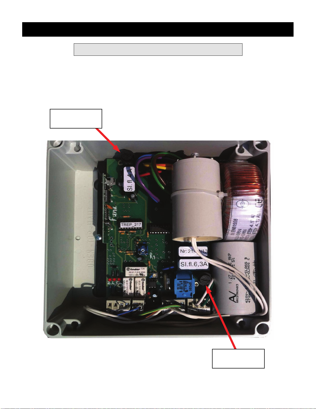
There are two fuses located in the control box. They are spring loaded in a barrel housing.
To remove, push down and turn counter-clockwise to release. Remove cap to check or re-
place fuse. Re-insert cap and push down while turning clockwise to lock.
Fuses - Checking / Replacing
Fuse # 1
4 amp
Fuse # 2
6.3 amp
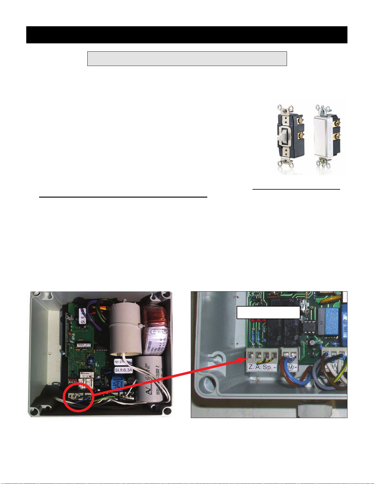
The Galaxy stair can be operated by use of the remote control (provided), a hard-wired wall switch
(optional) or both. This guide will help you set up your unit for wall switch operation.
The switch itself is purchased separately and is available at most hardware /
home improvement stores or electrical supply houses.
It should be a low voltage, momentary contact, center OFF type. One offered
by Leviton, (Product # 56081-2), is available in both toggle style and Decora
style as shown at right and works well in this application.
Step 1.
Locate the position of the electrical box to house the switch on the wall. The switch should be set at
a height which will prevent children from reaching it.
Run three low voltage wires from electrical box to where stair control box is located in attic. It may be
useful to use three different wire colors for easy identification.
Step 2.
Unplug the control box in attic from the power outlet and remove cover.
Remove wiring module from control box by grasping module and rocking slowly while pulling up to re-
lease it.
Control Box
Wiring Module
Addendum - Continued
Hard Wiring Instructions
Page 12 July 2014
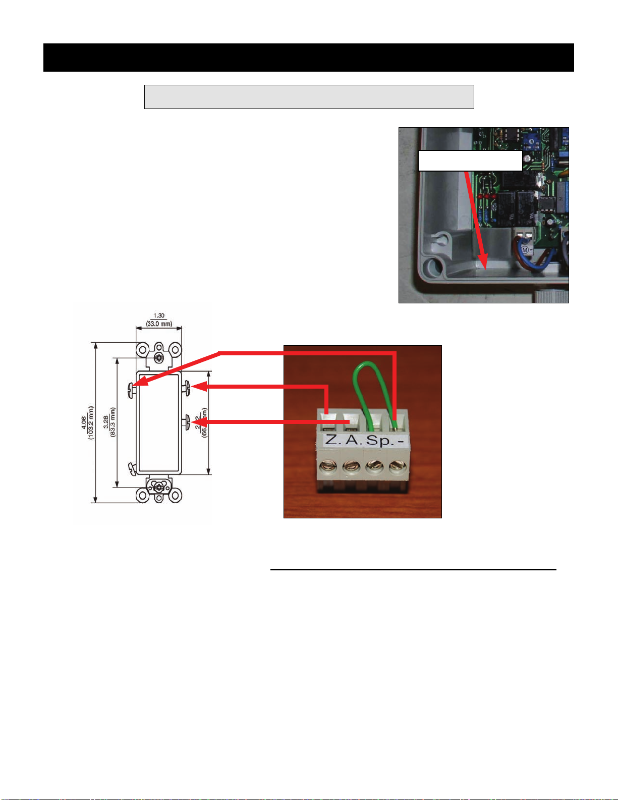
Step 3.
After removing module, drill small access hole for wiring into con-
trol box. Drill from the outside so shavings don’t enter.
Thread wiring through hole before connecting to module.
Step 4.
Slot “-” is for power to the switch.
Slot “Z” is for Up (Close the stair)
Slot “A” is for Down (Open the stair)
Loosen the three screws on front of module for slots shown above. Insert individual wires as shown
and secure each by re-tightening screws. Do not remove existing wire already in slot marked “-”.
Carefully press module back onto circuit board.
Note: It is advisable to fill hole around wires with clear rubber sealant to prevent insects, dirt or
moisture from entering box.
Step 5.
Plug the control box back into the power outlet
Drill Hole Here
Addendum - Continued
Hard Wiring Instructions
Page 13 July 2014
Addendum - Continued
Hard Wiring Instructions
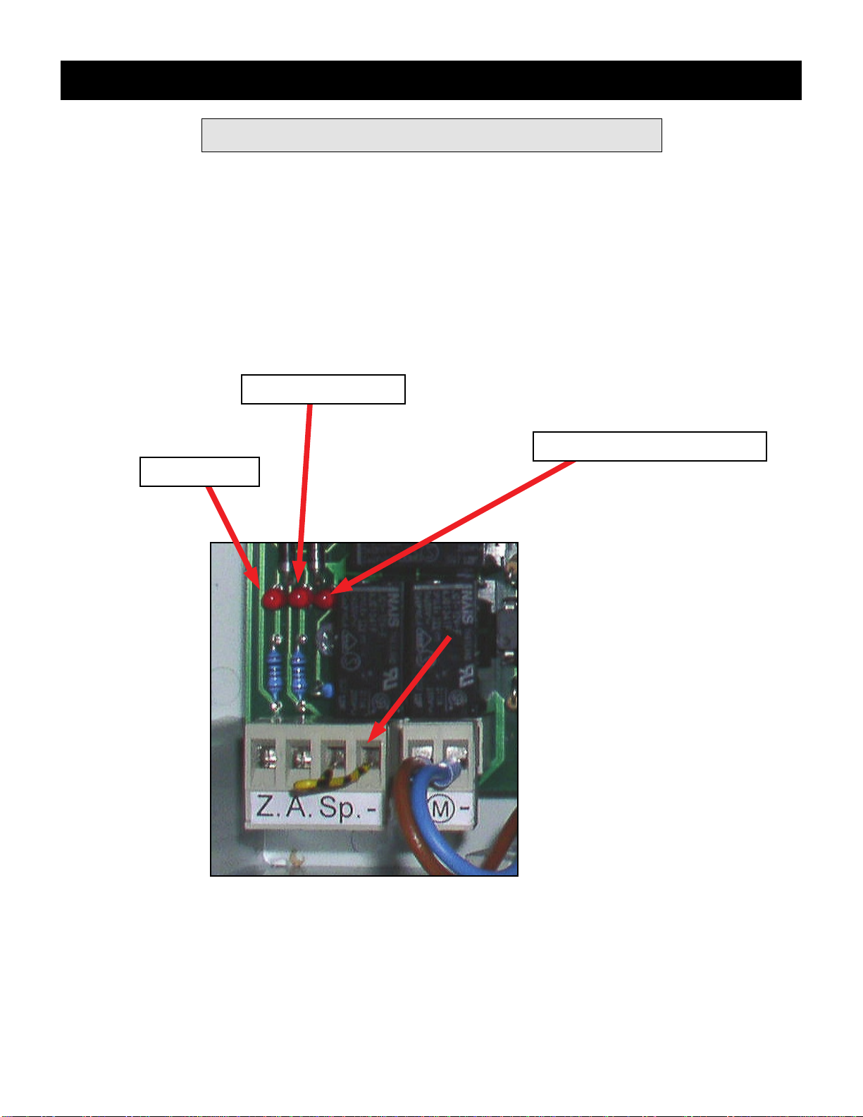
The power light at the far right should be on.
Test by having someone at the switch press the switch for both Up and Down. Corresponding light
should go on when pressed, as shown below.
If all is working properly, replace cover on control box. Your unit is now ready for use.
If you encounter any problems, contact Shelter Products LLC at 877-369-6996.
Down Light
Up Light Power Light - Always On
Page 14 July 2014

Addendum - Continued
Troubleshooting Guide
Condition Check
- Door will not open or close. - Check remote battery (battery is good if tip lights red when
buttons pressed).
- Check outlet where control unit is plugged in for power.
- Open control box and check if power light is on. See page 14.
- Check fuses. See Page 11.
- Check whether up / down light indicators on circuit board
light when remote buttons depressed. There will also be an
audible click when depressed.
- If you experienced a power outage at any time, reprogram
remote. See Page 10.
Power surges can also damage electronic circuit boards.
Using a surge protector is highly recommended.
- Door will not open - Open door and / or stair manually if closed. Press remote to
open and check if door latch retracts automatically.
- Door opens but stair will not fully
unfold. (starts and stops) - Is there a metal roof on the building? Metal roofs create dead
spots which can interfere with the remote’s signal.
- While closing, door stops short of
closing fully. (Does not go fully up into
frame).
- Check that bolts holding extra treads together at bottom of
stair are not over-tightened, as this will create resistance and
stop motor.
- While closing, door goes fully up into
frame but will not latch shut. - Steel hangers may have been over-tightened during installa
tion, slightly bowing steel trim and not allowing latch to enter
slot. Lightly file down lower edge of slot to allow latch to
engage.
Do not file too much as this will cause door to hang
lower than trim.
- For any other operating problems - Call us at 877-369-6996 for further assistance

LIMITED WARANTY
SP Partners, LLC warrants that the unit will be free from any defects in material and workmanship
for one year from purchase date provided that the stair is installed in compliance with the preceding
instructions and operated and maintained in accordance with these instructions and applicable
warnings.
This warranty specifically excludes any and all non-defect damage, any and all damage, injuries and
losses arising from improper installation of this product, unreasonable use to include exceeding the
specified weight limitations, and any and all labor charges incurred for removing or reinstalling a
repaired stair unit or any of its components.
During the warranty period stated, should the stair unit or any of its components exhibit a manufac-
turing defect please first call SP Partners, LLC at 877-369-6996 before dismantling the product in
order to determine the extent of the defect and what course of action needs to be taken to correct
the problem. A proof of purchase will be required in all cases.
ADDITIONAL EXCLUSIONS
SP Partners, LLC’s above-stated express limited warranty is being made in lieu of all implied
warranties of any kind, including those as provided by the Uniform Commercial Code for merchant-
ability of the product and for fitness of the product for a particular purpose. All such implied warran-
ties, including those of merchantability and/or fitness for a particular purpose, are excluded and
disclaimed. Furthermore, all claims for consequential damages and for incidental damages that may
arise from a breach of the above-mentioned express warranty are also excluded. In no event shall
SP Partners, LLC be liable for any breach of warranty and/or for any negligence and/or for any strict
liability which would exceed in damage amount the cost of the stair unit.
No representative or person is authorized to assume for SP Partners, LLC, any responsibility which
would be either an alternative to or in addition to the express product warranty as stated above. This
warranty gives you certain specific legal rights as were set forth above and any other rights that may
vary from state to state. If any portion of this express warranty is deemed to be unenforceable at any
time hereafter, any such provision shall be severed from this agreement, but all other terms, condi-
tions and provisions shall remain in full force and effect.
Tel: 877-369-6996
Website: www.RainbowAtticStair.com
Email: info@RainbowAtticStair.com
SP Partners, LLC
Table of contents
Other SP PARTNERS Ladder manuals


Popular Ladder manuals by other brands


Confer Plastics
Confer Plastics 8100X instructions

MONDELIN
MONDELIN Ninja Use and safety instructions

Stromberg Carlson Products
Stromberg Carlson Products LA-401 quick start guide

Easy Access
Easy Access WHDP OPERATIONAL SAFETY AND ASSEMBLY INSTRUCTIONS

Vorel
Vorel 17701 instructions

Roto
Roto Columbus installation manual

Dolle
Dolle LOFT LADDER Installation instruction

FACAL
FACAL GENIA Series Use and maintenance handbook

GRE
GRE AR-116802 installation manual

pixima fontanot
pixima fontanot RING Assembly instructions

brennenstuhl
brennenstuhl 1420440 Use and Operating Instructions

GIERRE
GIERRE AL065 Operating and maintenance instructions