SPAN PressureGuard EASY AIR Series User manual
P09564 R4 CO# 2340
OWNER’S MANUAL
PressureGuard®
EASY AIR®
Series
Span-America Medical Systems, Inc.
800-888-6752
www.spanamerica.com
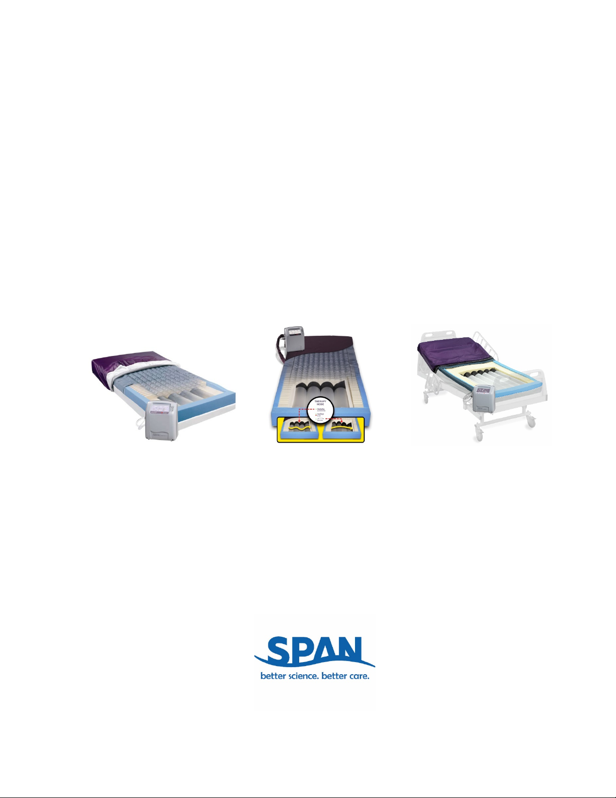
PressureGuard®
EASY AIR®
PressureGuard®
EASY AIR® LR
PressureGuard®
EASY AIR® XL

2
P09564 R4 CO# 2340

3
P09564 R4 CO# 2340
TABLE OF CONTENTS
DOCUMENT SYMBOLS .................................................................................................................................................................5
INTRODUCTION ..............................................................................................................................................................................6
INTENDED USE
INDICATIONS FOR USE
GENERAL DESCRIPTION
MODES OF OPERATION
PRODUCT DESCRIPTION.............................................................................................................................................................8
THE SCIENCE BEHIND THE EASY AIR LOW AIR LOSS DESIGN.................................................................................9
MATTRESS and CONTROL UNIT SETUP DIRECTIONS ..................................................................................................8
ELECTROMAGNETIC OR OTHER INTERFERENCE.......................................................................................................12
CONTROL UNIT SETTINGS – ALL MODELS .....................................................................................................................13
DIRECTIONS FOR USE
EASY AIR STANDARD..............................................................................................................................................................14
EASY AIR XL.................................................................................................................................................................................14
EASY AIR LR.................................................................................................................................................................................16
GENERAL DIRECTIONS FOR USE
ELEVATING HEAD OF BED....................................................................................................................................................17
BED RAILS ....................................................................................................................................................................................17
CPR...................................................................................................................................................................................................17
PATIENT TRANSPORT ............................................................................................................................................................17
POWER LOSS ...............................................................................................................................................................................17
BED LINENS.................................................................................................................................................................................17
INCONTINENCE PADS.............................................................................................................................................................17
SERVICE.........................................................................................................................................................................................17
ENVIRONMENTAL CONDITIONS FOR USE....................................................................................................................17
STORAGE AND TRANSPORTATION ..................................................................................................................................18
CLEANING
MATTRESS COVERS .................................................................................................................................................................
18
AIR CONTROL UNIT .................................................................................................................................................................19
PREVENTIVE MAINTENANCE
FILTER MAINTENANCE..........................................................................................................................................................20
POWER CORDS ...........................................................................................................................................................................21
MATTRESS....................................................................................................................................................................................21
SPECIFICATIONS..........................................................................................................................................................................23
ORDERING INFORMATION .....................................................................................................................................................23
TROUBLE SHOOTING GUIDE.................................................................................... Error! Bookmark not defined.
APPENDIX: PREVENTIVE MAINTENANCE LOG.............................................................................................................28

4
P09564 R4 CO# 2340
5
P09564 R4 CO# 2340
DOCUMENT SYMBOLS
This manual contains different typefaces and symbols to make the content easier to read and understand:
• Standard text – used for regular information.
• Boldface text – stresses a word or phrase.
• NOTE: - sets apart special information or important instruction clarification.
• The symbol below identifies a WARNING or CAUTION:
- A WARNING identifies situations or actions that may have an effect on patient or user
safety. Ignoring a warning could cause patient or user injury.
- A CAUTION points out special procedures or precautions that persons must obey to
avoid equipment damage.
• The symbol below identifies an ELECTRICAL SHOCK HAZARD WARNING:
• The symbol below identifies ALTERNATING CURRENT:
• The symbol below identifies TYPE B APPLIED PART:
6
P09564 R4 CO# 2340
INTRODUCTION
PRESSUREGUARD EASY AIR®Standard, XL and LR Models
WARNING: READ ALL INSTRUCTIONS BEFORE USING THIS UNIT.
INTENDED USE: A pressure management system used for the prevention and treatment of pressure injuries.
INDICATIONS FOR USE: The PressureGuard Easy Air is a unique powered, flotation therapy mattress providing
1) a pressure management surface for the prevention and treatment of pressure injuries, and 2) low air loss for
the removal of excess perspiration and body heat. It is intended for use on any standard hospital bed frame.
DESCRIPTION: The system consists of a two-part low air loss system of cover and coverlet, a foam shell, air
cylinder inflation system, and a control-unit housing a blower and a compressor. The foam shell has a high-
density foam topper, a patented Safety Edge™ contoured foam bolster around the perimeter and ends of the
mattress for added patient stability and positioning, and the unique Heel Slope™ feature designed to further
reduce pressure for the sensitive heel area. The air-cylinder inflation system is housed within the foam shell, and
consists of air-cylinders oriented lengthwise within the mattress. The control unit connects to the mattress at the
patient foot-end.
MODES OF OPERATION: On all versions of the PressureGuard Easy Air, the air flow for low air loss can be
turned ON or OFF. Standard Easy Air and Easy Air XL (bariatric) versions provide choice of two therapy modes of
operation, FLOAT or ALTERNATING. Easy Air LR version provides choice of three therapy modes of operation,
FLOAT, ALTERNATING, or ROTATION.
To reduce the risk of burns, electrocution, fire or injury to persons:
READ ALL INSTRUCTIONS BEFORE USING THIS UNIT.
1. Use this unit only for its intended use and with recognized accessories which are described in the operating
instructions; use of other accessories or materials may degrade minimum safety level.
2. Never operate the product’s powered control unit if it has a damaged cord or plug, is not working properly,
has been dropped or damaged, or has been exposed to water. Contact Span-America Medical Systems, Inc.
for examination and repair.
3. Keep the cord away from heated surfaces. Discontinue use if power cord is damaged or worn.
4. Never drop or insert any object into any opening or hose. Keep away from sharp objects.
5. Do not use outdoors.
6. Do not place or store product where it can fall or be pulled into a tub or sink.
7. Do not place in or drop into water or other liquid.
8. Do not reach for a product that has fallen into water. Unplug immediately.
9. Possible explosion hazard if used in the immediate proximity of flammable gases (risk of explosion).
10. Use only original spare parts and consumables.
11. Plug this product into a correctly grounded outlet only.
12. Before cleaning, unplug unit from its power source. Failure to do so could result in personal injury or

7
P09564 R4 CO# 2340
equipment damage.
13. Do not use harsh cleansers, solvents, or detergents. Do not expose the unit to excessive moisture.
Equipment damage could occur.
Warning: This product contains/may contain chemicals known to the state of California to cause cancer
and/or birth defects or other reproductive harm.
We believe the PressureGuard Easy Air sets a new standard for
low air loss mattress systems.
Thank you for choosing Span-America!
8
P09564 R4 CO# 2340
PRODUCT DESCRIPTION
Span-America’s patented use of non-collapsible “air diffusion matrix” fabric in both the inner air delivery cover
and the outer removable coverlet maintains an air pathway underneath the user, thus transporting moisture
vapor away from the user’s skin. Both the inner air-delivery cover and the outer removable coverlet are
bacteriostatic, flame resistant and fluid proof. Since they do not allow fluids to penetrate the surface to the
mattress, maintenance is minimal. The air-cylinder inflation system and the foam shell work in concert to
maintain low interface pressures throughout the surface, making the Easy Air effective for treatment of pressure
injuries by preventing further tissue breakdown.
Close-up illustrations of the Outer Removable Coverlet and the Inner Air-Delivery Cover, and an
explanation of the Science behind the design are found on page 9.
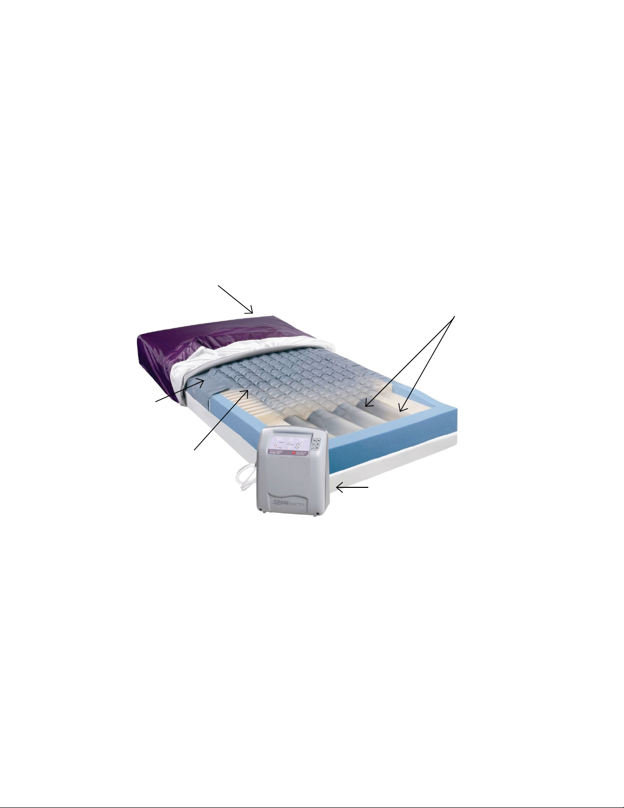
Illustration of individual parts of the PressureGuard Easy Air:
1. Outer Removable Coverlet
3. Air Cylinders
2. Inner Air Delivery Cover
4. Foam Shell with Geo-Matt
topper and Safety-Edge
bolster design
5. Control Unit

9
P09564 R4 CO# 2340
ILLUSTRATION DESCRIPTIONS
1. Outer Removable
Coverlet:
The purple-colored coverlet is fluid proof, cleanable and flame resistant. It can
be replaced if damaged or worn. The outer coverlet is highly vapor permeable
(4500 grams/meter2/24 hours) and fluid-proof. Both of its fabrics (smooth top
fabric and the crush-proof air diffusion matrix fabric) are bacteriostatic.
Coverlet can be routinely wiped clean and disinfected in place, or can be
removed and machine laundered according to directions in this manual.
2. Inner Air-Delivery
Cover The gray, multi-layered cover serves as a barrier, protecting the inside of the
mattress from both fluids and vapors, while supplying air to the
microenvironment between the cover and coverlet. Unlike the purple removable
coverlet, it is intended to remain on the mattress at all times. It can be cleaned
and disinfected in place using standard hospital, medical grade products. The air
delivery cover is a greenish gray urethane coated fabric with a welded pattern
and air holes designed to deliver air flow to the top of the mattress to flow
underneath the patient in the removal of moisture from the patient’s skin.
3. Air Cylinders The inflation system consists of air cylinders that run lengthwise underneath the
body. Unlike typical low air loss systems, the cylinder inflation system does not
lose air from the inflation system for "low air loss", and can be programmed to
perform either Flotation or Alternating Pressure; in the LR model they can also
perform Lateral Rotation. The cycles and inflation levels are designed to provide
and maintain low interface pressures throughout the mattress, and to
redistribute peak interface pressure points during all Therapy Modes.
4. Foam Shell The Geo-Matt®style foam topper is a high density, medical grade foam. The
unique geometric design consists of over 800 individual cells, each of which acts
individually to customize patient comfort, support, and pressure reduction and
redistribution. This foam topper is 1.5" in height and includes the unique Heel
Slope™ feature, designed to further reduce pressure for the sensitive heel area.
The patented Safety Edge™ consists of contoured foam bolsters around the
perimeter and ends of the mattress for added patient stability and positioning.
5. Control Unit The quiet, energy efficient control unit houses both a high volume air blower and
a lower volume air compressor. The blower component provides air for the low
air loss function through the cover/coverlet,
while the compressor component provides air to the air-cylinder inflation system.
The filters on the control unit need to be cleaned regularly.

10
P09564 R4 CO# 2340
THE SCIENCE BEHIND EASY AIR LOW AIR LOSS DESIGN
Easy Air’s exclusive “Air Diffusion Matrix” design maximizes removal of
excess moisture (i.e., perspiration) from the user’s skin. Moisture passes in
vapor form down through the cover, where a continuous air current takes it
away before it can re-form as liquid.
The Air Diffusion Matrix fabric is not collapsible, ensuring a pathway for a
constant flow of air beneath the patient. Compare to typical low air loss
designs that cause the patient’s body to press the cover directly onto the air
holes, closing off the flow of air beneath the patient.
Outer Removable Coverlet
and
Inner Air-Delivery Cover
11
P09564 R4 CO# 2340
MATTRESS AND CONTROL UNIT SET-UP DIRECTIONS
1. Place the mattress on a standard hospital bed frame or on a box spring, with the purple coverlet facing up,
and the connector access at the foot-end of the bed, to the patient's right. Note that the connector access is
on the inner gray top surface air delivery cover, which should also be facing up, under the purple coverlet.
2. Hang the air-control unit on the foot-end of the bed or place on the floor as desired. Avoid blocking vent
holes for filter on the back of the control unit housing.
3. Plug the power cable into the connector module on the air-control unit (on lower lefthand side when facing
the control unit) and plug the opposite end into the wall outlet.
Always plug the power cable securely into the wall outlet. Make sure the wall-
mounted outlet will accommodate a heavy duty or hospital-grade plug and that the outlet is in good
working order. The plug of the power cord should fit tightly into the wall outlet. The plug body, the wall
outlet, and the wall plate should not be cracked or chipped. The plug blades should be securely retained
in the plug body. The ground pin of the plug should be intact and secure.
Do not connect the power cord to an extension cord or to a multiple outlet strip. If the use of extension
cords or multiple outlet strips cannot be avoided, use only heavy duty or hospital-grade connectors that
are approved by the facility engineering department. Multiple outlet strips should be mounted on a
fixed object to reduce the risk of liquid spills and physical damage. In addition, if multiple-receptacle
outlet boxes are used, they also should be protected from the risk of liquid spills and physical damage.
All extension cords and multiple outlet strips should be tagged and inspected routinely.
Do not cover the power cord with a rug or carpet. Rugs or carpets can prevent normal air flow, which
can lead to greater heat built-up. Place the cord in a low or no traffic area. Check to be sure the motion
of the bed does not interfere with the bed’s power cord or plug.
Never thread power cords through mechanical parts of the bed or bed rails where normal bed
movement may damage or cut the cord.
Note: If the pump is quickly restarted after a power interruption, you may encounter fluctuating power
indicated by blinking lights. Turn power off. Wait at least 5 seconds before restarting.
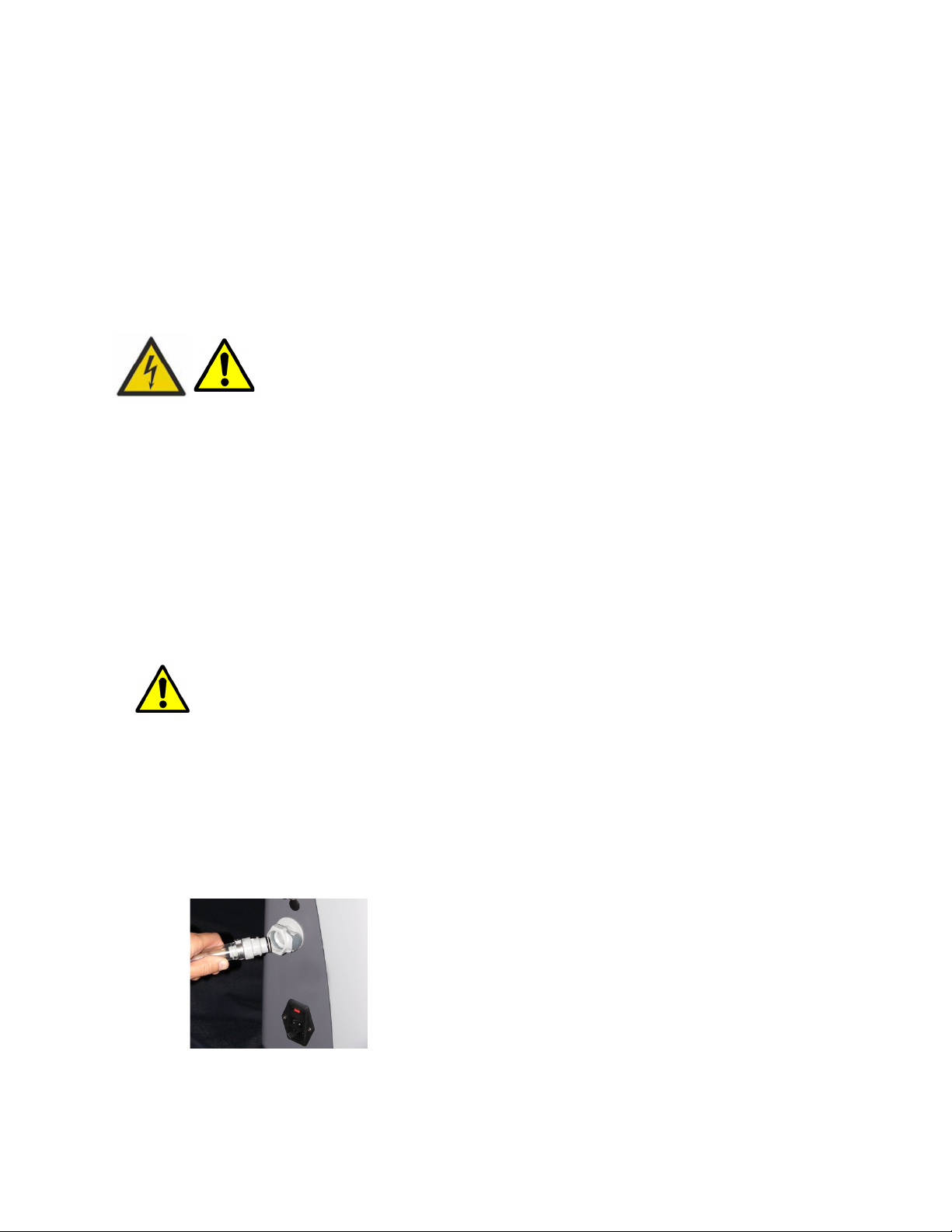
4. Connect the air lines extending from the mattress into place on the side of control unit.
- Air Delivery Line: The large diameter air line delivers a high volume air flow to the top layer of
mattress. For all models, click the male fitting of the large diameter air line into place in the female
air outlet on the side of the control unit. To disconnect, press grey button on the outlet. This will
release and eject the air line.
- Support Cylinder Air lines: The small diameter air lines deliver lower volume air flow to the support
cylinders inside the mattress. On Standard model, click in place the two separate male elbow fittings,
Attaching main air delivery line

12
P09564 R4 CO# 2340
which are interchangeable. Verify secure connection with two clicks. On the LR model (four fittings
mounted into one connection plate.) and XL (six fittings mounted into one connection plate) models,
click connectors into place in appropriate fittings on side of control unit. Verify secure connection
with “click” for both metal connectors.
- To disconnect: On standard unit, press silver release button located on each air line connector. On LR
and XL versions, use thumb and forefinger to press concurrently the
two silver release buttons located on the uppermost left and lowermost right connectors. This will
release and eject the air line connector plate.
!
Never thread air lines through mechanical parts of the bed or bed rails where raising, lowering,
or gatching of the bed may damage the air lines or the control unit itself. Check to be sure the
routing of the air lines or the motion of the bed does not impede air flow by crimping the air lines.
ELECTROMAGNETIC OR OTHER INTERFERENCE
This equipment generates, uses and can radiate radio frequency energy and, if not installed and used in
accordance with the instructions, may cause harmful interference to other devices in the vicinity. However,
there is no guarantee that interference will not occur in a particular installation.
If this equipment does cause harmful interference to other devices, which can be determined by turning the
equipment off and on, the user is encouraged to try to correct the interference by one or more of the following
measures:
-Reorient or relocate the receiving device.
-Increase the separation between the equipment.
-Connect the equipment into an outlet on a circuit different from that to which the other device(s)
are connected.
-Consult the manufacturer for help.
Attaching support cylinder
connection plate on Easy Air LR
(model 8200)
Attaching support cylinder
connection plate
On Easy Air XL (model 8300)
Easy Air Standard Model
(model 8000)

13
P09564 R4 CO# 2340
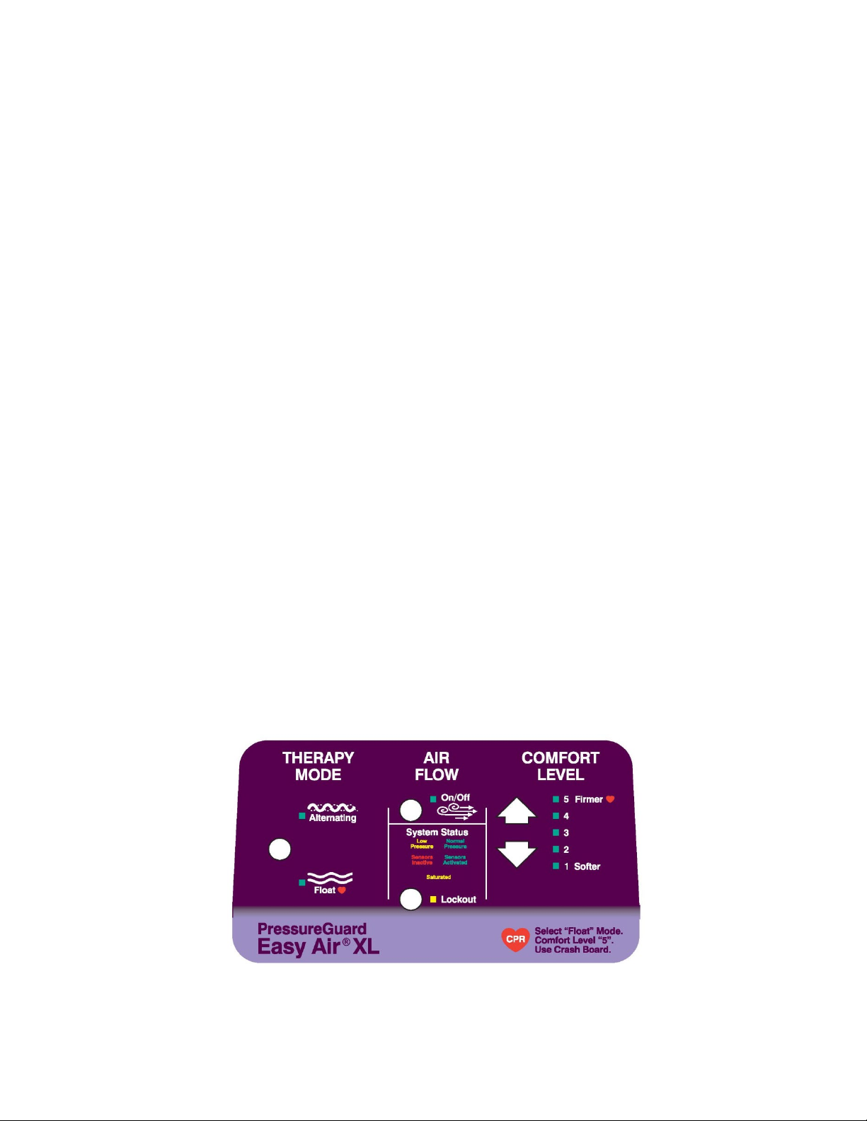
CONTROL UNIT SETTINGS
1. Turn unit ON at the switch provided on the lower left-hand side of the air-control unit.
2. Select the desired THERAPY MODE.
- For Standard and XL models, select FLOAT or ALTERNATING as desired.
- For LR model, select FLOAT or ALTERNATING or ROTATION.
3. AIR FLOW - Select OFF or ON as desired. Air flow ON is recommended where prevention of skin maceration
is desired.
4. LOCKOUT – This feature can be used to eliminate accidental or
unintended changes to the control unit settings. To engage, press
LOCKOUT firmly and hold for three to four seconds until indicator light
turns on. To disengage, press LOCKOUT again and hold firmly for 3-4
seconds until light turns off, indicating that the control unit settings are
again unlocked and can be adjusted as desired.
5. COMFORT LEVEL: For best possible pressure management, maximize immersion and envelopment by
initially setting the “COMFORT LEVEL” on the control panel to the softest selection appropriate for the
patient, in accordance with the stated weight limits:
Easy Air, Easy Air LR:
•For patients up to 120 lbs., begin with level 1 (“Max. Immerse”).
•For patients weighing more than 120 lbs. (up to 500 lbs.) begin with Level 2.
Adjust for user comfort as desired, using up and down arrow buttons.
Easy Air XL:
•Because it is not necessary for bariatric patient, the XL model does not include
“Max. Immerse” setting. Begin in lowest setting and adjust for comfort.
NOTE: Allow the mattress to inflate for about 20 minutes before putting a patient on it.

14
P09564 R4 CO# 2340
DIRECTIONS FOR USE
PRESSUREGUARD EASY AIR®STANDARD MODEL
1. Immediately after the control unit is switched ON, all lights on the control panel will illuminate for 1-2
seconds while the system performs a self check. If correct system air pressure is not reached within 60
seconds, the amber LOW PRESSURE indicator will illuminate. LOW PRESSURE indicator will remain until
being replaced by the green NORMAL PRESSURE indicator, signaling that the mattress is ready for patient
use. If NORMAL PRESSURE indicator does not illuminate within 20 minutes of power up, contact Span-
America for assistance.
2. Select the preferred mode of operation by pressing the toggle button under THERAPY MODE on the control
unit’s front panel. Select:
ALTERNATING: Air cylinders 1 and 3 deflate while 2 and 4 inflate. Pairs will go through one complete
alternation cycle every 15 minutes.
OR
FLOAT evenly inflates all 4 air cylinders, providing powered flotation.
3. Press the AIR FLOW toggle button to select AIR FLOW ON or OFF as preferred. AIR FLOW is ON when light
is illuminated, and OFF when light is not illuminated.
4. In normal operation, the green NORMAL PRESSURE indicator should be illuminated. If the amber LOW
PRESSURE indicator illuminates, verify air lines are not crimped or kinked preventing proper air flow and
that all air line connections are secure. If the problem is not resolved, remove the patient from the surface
and discontinue use. For assistance, contact Span-America at 800-888-6752 8:00 AM – 5:00 PM EST Monday
through Friday.
5. Set COMFORT LEVEL as described on page 11.
15
P09564 R4 CO# 2340
DIRECTIONS FOR USE
PRESSUREGUARD EASY AIR®XL MODEL
1. Immediately after the control unit is switched ON, all lights on the control panel will illuminate for 1-2
seconds while the system performs a self check. If correct system air pressure is not reached within 60
seconds, the amber LOW PRESSURE indicator will illuminate. LOW PRESSURE indicator will remain until
being replaced by the green NORMAL PRESSURE indicator, indicating that the mattress is ready for patient
use. If NORMAL PRESSURE indicator does not illuminate within 20 minutes of power up, contact Span-
America for assistance.
2. Select the preferred mode of operation by pressing the toggle button under THERAPY MODE on the control
unit’s front panel. Select:
ALTERNATING: The six cylinders work in pairs. Air cylinders 1 and 4 deflate, then 2 and 5, then 3 and 6.
Pairs will go through one complete deflation/inflation cycle every 22 minutes.
OR
FLOAT evenly inflates all 6 air cylinders, providing powered flotation.
3. Press the AIR FLOW toggle button to select AIR FLOW ON or OFF as preferred. AIR FLOW is ON when light
is illuminated, and OFF when light is not illuminated.
4. In normal operation, the green NORMAL PRESSURE indicator should be illuminated. If the amber LOW
PRESSURE indicator illuminates, verify air lines are not crimped or kinked preventing proper air flow and
that all air line connections are secure. If the problem is not resolved, remove the patient from the surface
and discontinue use. For assistance, contact Span-America at 800-888-6752 8:00 AM – 5:00 PM EST Monday
through Friday.
5. On the XL model, the COMFORT LEVEL is not intended to be set according to the individual user’s specific
weight. Instead, for best possible immersion and pressure distribution, begin with the softest setting, setting
1. If user expresses discomfort, level can be adjusted as desired to accommodate comfort.
DIRECTIONS FOR USE

16
P09564 R4 CO# 2340
PRESSUREGUARD EASY AIR®LR MODEL
1. Immediately after the control unit is switched ON, all lights on the control panel will illuminate for 1-2
seconds while the system performs a self check. If correct system air pressure is not reached within 60
seconds, the amber LOW PRESSURE indicator will illuminate. LOW PRESSURE indicator will remain until
being replaced by the green NORMAL PRESSURE indicator, indicating that the mattress is ready for patient
use. If NORMAL PRESSURE indicator does not illuminate within 20 minutes of power up, contact Span-
America for assistance.
2. Select the preferred mode of operation by pressing the toggle button under THERAPY MODE on the control
unit’s front panel.
ALTERNATING: Air cylinders 1 and 3 deflate while 2 and 4 inflate. Pairs will go through one complete
alternation cycle every 15 minutes.
FLOAT: Stops the alternating or rotating movement of the mattress and evenly inflates all four air
cylinders. The FLOAT indicator light will illuminate and the mattress will achieve uniform support with
no movement within five minutes.
ROTATION: Air cylinders 1 and 2 inflate while 3 and 4 deflate, gently rolling the patient laterally. Cycles
complete every 15 minutes, rotating the patient from side to side, approximately 20 degrees in each
direction.
3. Press the AIR FLOW toggle button to select AIR FLOW ON or OFF as preferred. AIR FLOW is ON when light
is illuminated, and OFF when light is not illuminated.
4. In normal operation, the green NORMAL PRESSURE indicator should be illuminated. If the amber LOW
PRESSURE indicator illuminates, verify air lines are not crimped or kinked preventing proper air flow and
that all air line connections are secure. If the problem is not resolved, remove the patient from the surface
and discontinue use. For assistance, contact Span-America at 800-888-6752 8:00 AM – 5:00 PM EST Monday
through Friday.
5. Set COMFORT LEVEL as described on page 11.

17
P09564 R4 CO# 2340
GENERAL DIRECTIONS FOR USE OF ALL EASY-AIR MODELS
ELEVATING HEAD OF BED (HOB): All support surfaces using air as a support medium are designed for
distributing pressures over the body in a flat, horizontal position. Bending the support surface and the body at
the midpoint when elevating the HOB concentrates the body weight over the center of the surface, stressing that
small area. This extreme change in dynamics creates a challenge for all air support surfaces. Maximum pressure
management benefits are realized between zero and 30 degrees HOB elevation. Beyond 30 degrees, the
amplitude of the changes in the air cylinders begins to decrease in proportion to the increased elevation of the
HOB. Although the Easy Air will maintain its support and therapeutic capabilities up to and including 70 degrees
HOB, for maximum benefit we recommend that any pressure management surface be used with the head of the
bed elevated as little as possible, and for limited periods at a time.
BED RAILS: Due to concerns over the possibility of patient entrapment, Span-America recognizes that the use of
rails of any length is a matter currently addressed by federal and state laws/guidelines, and by individual facility
protocol. It is the responsibility of the facility to be in compliance with these laws, which typically require that
decisions on the use of bed rails of any type are based on assessment of the physical and mental status of each
patient individually. If bedrails are needed by the patient to prevent fall-related injury, as determined by this
facility assessment, we recommend that the bedrails be locked in the up position at all times. We do not require
use of bedrails with the Easy Air mattress unless the patient is deemed to be safer with them than without them.
CPR (Cardiopulmonary Resuscitation): The face plate of all Easy Air models indicates
recommended settings for CPR. The standard for life support recommended by the American Heart Association
recommends a hard level surface such as a crashboard, or moving the person to the floor if possible.
For performing CPR on all PressureGuard Easy Air Models: 1) Select the FLOAT Mode; 2) Select the firmest
COMFORT LEVEL; 3) Place a crash board underneath the user; 4) Follow standard CPR procedures.
PATIENT TRANSPORT: The patient can remain on the mattress while the mattress and bed frame are being
moved, with proper safety precautions taken. Unplug the power connector from the wall receptacle. The
inflation of the mattress will be maintained and the air will equalize in the air cylinders.
CAUTION: DO NOT MOVE PATIENT ON MATTRESS ONLY.
Mattress should not be used alone for patient transport.
POWER LOSS: If power is lost, DO NOT UNPLUG the control unit, and DO NOT DISCONNECT the air lines from
the control unit. The air-cylinder system will equalize pressure in the support cylinders, and maintain inflation
for days or weeks, functioning as a non-powered air flotation mattress. All models will restart to the exact
therapy mode and air flow mode programmed in before power was lost or turned off. As a safety measure,
comfort level will reset to setting “2” upon power up (see Comfort Level page 13). Allow approximately 5
minutes after power is restored to achieve normal therapy mode functions upon power up.
BED LINENS: Seven-inch deep fitted sheets are recommended.
INCONTINENCE PADS: Pads specifically designed for use with low air loss mattresses are recommended.
SERVICE: Return the control unit for repair or service to Span-America Medical Systems. Repairs to be
performed by manufacturer only. Call 800-888-6752, 8 am – 5 pm EST M-F.
ENVIRONMENTAL CONDITIONS FOR USE:
• Indoor Use
Altitude up to 2000 meters
• Temperature 5° C to 40° C
• Maximum relative humidity 80% for temperatures up to 31° C, decreasing linearly by 50% relative
humidity at 40° C

18
P09564 R4 CO# 2340
• Mains Supply Voltage Fluctuation up to 10 +/-% of the nominal voltage
• Overvoltage Category II
• Pollution Degree 2
STORAGE AND TRANSPORTATION
Store the mattresses in a clean, dry place. Once the mattress is removed from the box, store flat on a clean
surface. When removing mattress from storage, always ensure the internal inflation system is aligned correctly
prior to placing a patient on the surface. Avoid temperature extremes (below freezing or above 120oF). Allow to
acclimate to room temperature before use. Do no stack more than 10 high. Do not stack other equipment on top
of the mattresses.
Store the controllers in a clean, dry place, protected from accidental damage or falls. Avoid temperature
extremes (below freezing or above 120oF). Do not stack other equipment on top of the controller. For
transportation, secure to prevent damage or falls. For shipment, use box and packaging as provided by the
manufacturer.
CLEANING:Clean and disinfect mattress covers following contamination with bodily fluids and between
patients. Both the inner cover and the removable coverlet can be cleaned in place by wiping with neutral suds
and lukewarm water. Rinse and allow to air dry for approximately 20-30 minutes before use. For hard to clean
spots, use liquid cleaner with soft sponge in the concentration recommended by the manufacturer. DO NOT USE
HARSH CLEANERS OR SOLVENTS.
If desired, removable coverlet can be machine-laundered using cold or warm water and a cold rinse cycle. Begin
wash cycle, add detergent, allow to agitate for two minutes, then place coverlet in washer. Tumble dry using low
heat or no heat, or allow to air dry.
CAUTION: USE OF HIGH HEAT IN WASHING OR DRYING WILL DESTROY THE COVERLET.
For long-term incontinent applications, clean and disinfect cover daily. A scented cleaner/disinfectant is
recommended. Iodophor type disinfectants (e.g. Betadine) will stain the fabric.
For disinfection, phenolic or quaternary type disinfectants are recommended. Disinfectants should be hospital
grade (tuberculocidal). Follow manufacturer’s instructions for use concentrations, contact times and rinsing.
Contamination with blood on the fabric can be disinfected with a 1:10 dilution of household bleach (5.25%
sodium hypochlorite) as recommended by the CDC. The use of bleach at improper dilutions may result in fabric
discoloration and fluid pass-through.
Where surveillance and epidemiology indicate ongoing transmission of C. difficile, an EPA registered
hypochlorite-based disinfectant is recommended. Follow the manufacturer’s instructions for use concentrations,
contact times and rinsing. Generic sources of hypochlorite (e.g. household chlorine bleach) may also be used.
Prepare the disinfection solution fresh daily at a 1:10 dilution. Improper dilutions may result in ineffectiveness
and higher than recommended concentrations will damage the fabric.
Note: Alcohol-based disinfectants are not effective against C. difficile and should not be used to disinfect
environmental services. For further information relative to this organism and infection control in the healthcare
setting, please refer to www.cdc.gov/ncidod/hip.
Do not puncture the mattress with needles or sharp instruments. This may result in loss of
integrity of the mattress air system or top surface low air loss bladder, and will void the warranty. Inspect the
covers and zipper area for signs of damage, puncture, or wear that could result in fluid pass-through. If the cover
is stained, soiled, or torn, inspect the internal components for signs of contamination. If contamination is evident,
quarantine the mattress and remove from service following infection control procedures.

19
P09564 R4 CO# 2340
If required, the air control unit can be cleaned and disinfected.
Turn unit off and unplug from wall before cleaning. [Note: The mattress will maintain air with the
unit unplugged. The unit will resume previous setting when powered back up].
Wipe down with using damp sponge or cloth that has been thoroughly wrung out to remove
excess liquid. Do not allow liquids to penetrate the user panel.
For cleaning, use neutral suds and lukewarm water. For disinfection, phenolic or quaternary type disinfectants
are recommended. Disinfectants should be hospital grade (tuberculocidal). Follow manufacturer’s instructions
for concentrations and contact times.
20
P09564 R4 CO# 2340
PREVENTIVE MAINTENANCE
FILTER MAINTENANCE
• The control unit contains a high volume air blower that requires filtered air for proper
operation.
• The two-part filter system is located on the bottom rear of the unit.
•The larger outer filter is designed to be removed, cleaned, and re-used. [Fig. 1 & 2]
•The smaller inner filter is located directly beneath the larger removable filter [Figure 3]. THE SMALLER
FILTER IS NOT TO BE REMOVED. It is designed to be cleaned in place, from outside of the unit.
CAUTION: For maximum effectiveness, and to prolong the life of the unit, cleaning of the two-part filter
system should be performed at least once every 180 days of use. If the control unit is used in an area with
high concentration of dust or cigarette smoke, the filter should be cleaned as frequently as once every 30 or
60 days for maximum operation.
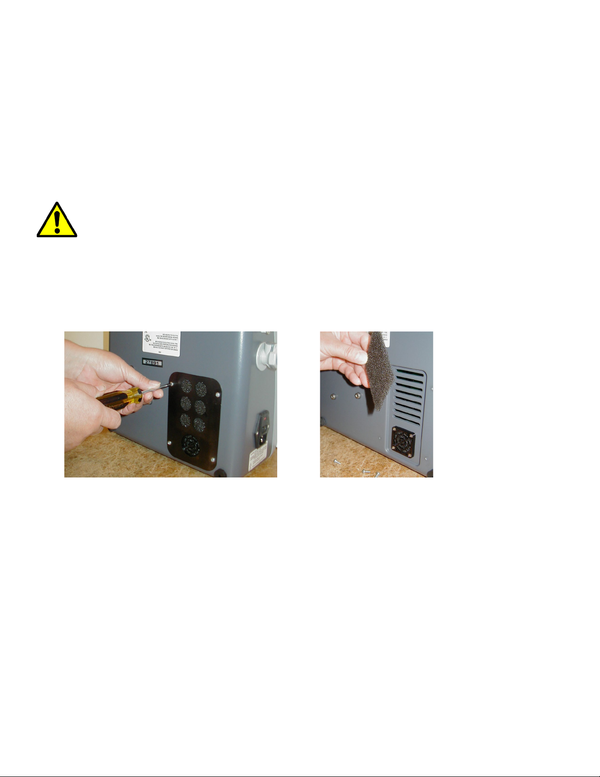
TO CLEAN THE TWO-PART FILTER SYSTEM
1. Turn unit OFF. Remove the four screws on the filter housing plate, which is found at the bottom rear of the
control unit [Figure 1].
Figure 1 Figure 2
2. With plate off, pull filter out [Figure 2].
3. Wash filter using mild soap and water. Pat dry with towel.
NOTE: If filter is damaged or cannot be easily cleaned, it should be discarded and replaced with a new filter,
Span-America part number P02549.
This manual suits for next models
19
Table of contents
Other SPAN Medical Equipment manuals


Popular Medical Equipment manuals by other brands


Chattanooga
Chattanooga INTELECT RPW LITE Operation / installation instruction

Canon
Canon AX-C4343W Technical document

Gima
Gima 34020 Use and maintenance book

Mercado Medic
Mercado Medic REAL 8100 USER and CARE INSTRUCTIONS

Game ready
Game ready GRPro 2.1 Use guide

United Care B.V.
United Care B.V. Wendy 3 manual