SPAN PressureGuard CustomCare User manual
OWNER’S MANUAL
Span-America Medical Systems, Inc.
Greenville, SC 29615
800-888-6752
®


P09588, Rev. 6 CO # 1848
TABLE OF CONTENTS
DOCUMENT SYMBOLS .................................................................................................................................................................2
INTRODUCTION ..............................................................................................................................................................................3
General Description
Indications
Modes of Operation
CONSTRUCTION AND DESIGN FEATURES..........................................................................................................................5
Illustration Descriptions.....................................................................................................................................................5
DIRECTIONS FOR MATTRESS SET-UP
Models for flat deck frames, including CareAssist®. ..............................................................................................7
DIRECTIONS FOR POWERED USE (all models) ................................................................................................................8
Control Unit Functions ..........................................................................................................................................................8
On/Off
Comfort Level
Therapy Mode
Low Pressure
Auto Firm
Audible Alarm On/Off
Disconnect/Wait: Resetting
ELECTROMAGNETIC OR OTHER INTERFERENCE.......................................................................................................11
POWER LOSS .................................................................................................................................................................................11
PATIENT TRANSPORT ..............................................................................................................................................................11
HEAD-OF-BED ELEVATION ....................................................................................................................................................11
TROUBLESHOOTING PATIENT COMPLAINTS ...............................................................................................................12
GENERAL DIRECTIONS.............................................................................................................................................................13
•Bed Linens
•Bed Rails
•CPR
•Storage and Transportation
•Environmental Conditions of Use
•Service
•Warranty
•Use in Wound Care
•Cleaning
•Waste Disposal
•Air Filter Preventive Maintenance
•Routine Inspection of Power Cords
•Mattress
•EMC
SPECIFICATIONS..........................................................................................................................................................................19
ORDERING INFORMATION ....................................................................................................................................................20
TROUBLE-SHOOTING GUIDE .................................................................................................................................................
21
PRODUCT WARRANTY .............................................................................................................................................................22
MAINTENANCE AND REPAIR LOG .....................................................................................................................................24


2
P09588, Rev. 6 CO # 1848
DOCUMENT SYMBOLS
This manual contains different typefaces and symbols to make the content easier to read and
understand:
•Standard text – used for regular information.
•Boldface text – stresses a word or phrase.
•NOTE: - sets apart special information or important instruction clarification.
Document Symbols
WARNING or CAUTION
Direct Current
WARNING: Situations or actions that
may have an effect on patient or user
safety. Ignoring a warning could cause
patient or user injury. IP21
Protection against the ingress of
fingers or similar objects and
dripping water
CAUTION: Points out special procedures
or precautions that persons must obey to
avoid equipment damage. Authorized Representative in the
European Community
See the user manual for use instructions
Potential trip hazards
Electrical shock hazard warning
Manufacturer
WEEE
Double Insulated system
Type BF applied part EN 60601-1-2 Electromagnetic Emissions
European Conformity Marking IEC 60601-1 Electrical Safety
Foot End
Keep Dry or Do Not Wet
Alternating current Not made with natural rubber latex
Serial number Quantity
Non Sterile
Catalogue Number
Batch Code
Humidity limitation
Temperature limitation

3
P09588, Rev. 6 CO # 1848
INTRODUCTION
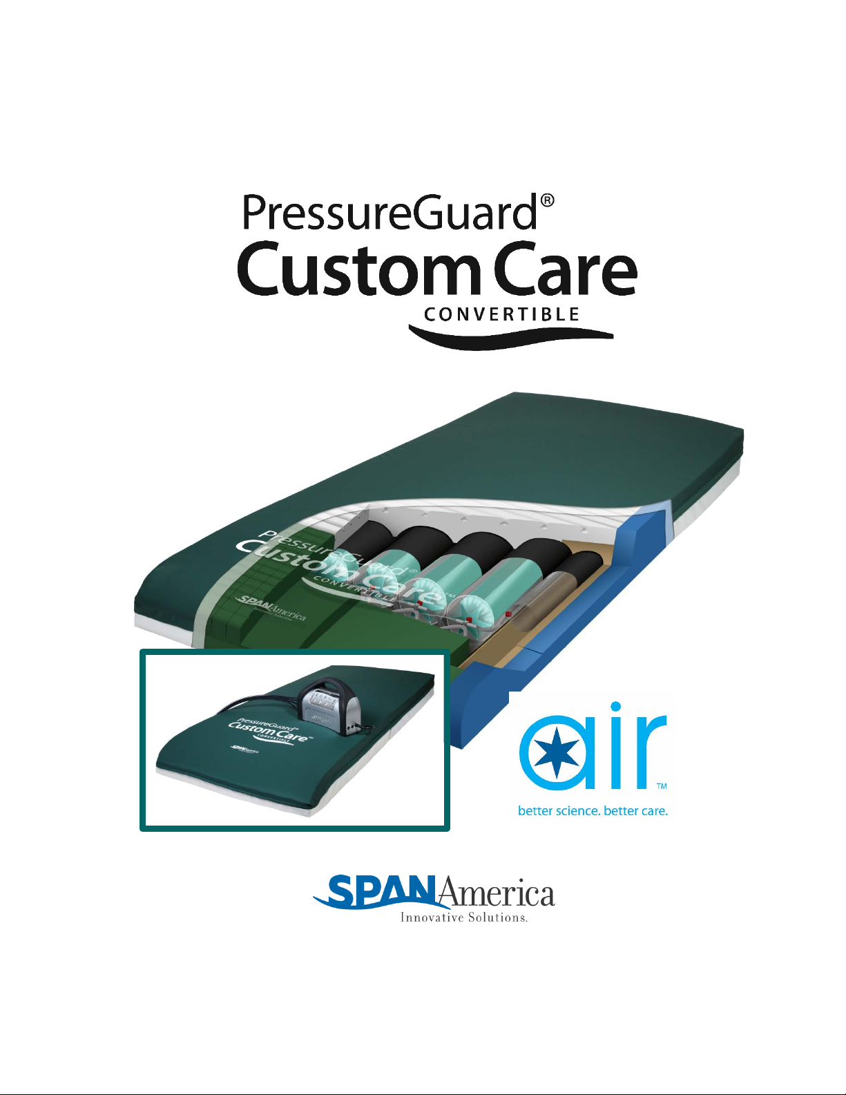
PressureGuardCustom CareConvertible
Non-powered therapy surface with add-on powered control unit
Introduction
The Custom Care®Convertible is a non-powered treatment surface featuring a patented air therapy
design that automatically adjusts a network of interconnected air cylinders and elasticized
reservoirs to the appropriate, therapeutic level, regardless of the user’s weight or position. It is
intended for use as a non-powered reactive therapy surface, or as a powered active therapy surface
via the addition of a powered air control unit.
DESCRIPTION: The system consists of a foam shell with a high-density, zoned foam topper
serving as the support surface underneath the patient. The foam shell also includes contoured
foam bolsters at the sides and ends of the mattress, providing added patient stability and
positioning. The system also includes the unique Heel Slope®feature, designed to further reduce
pressure for the sensitive heel area. Within the foam shell is housed the inflation system,
consisting of air cylinders which run lengthwise within the mattress. The optional, add-on
powered control unit connects to the mattress at the patient foot-end and provides alternating
pressure and rotation therapy modes. The system also includes an auto firm mode to provide a
firm support surface to use while providing patient care and to assist in patient transfer. A
disconnect feature resets the inflation level back to an ideal therapeutic setting for use of the
support surface without the control unit.
INDICATIONS FOR USE: Custom Care®Convertible models are intended for the prevention and
treatment of pressure ulcers. Powered modes are intended for active wound treatment, and may
be indicated for use as a preventive tool against further complications associated with critically
ill patients or immobility.
Contraindication: The PressureGuard Custom Care Convertible™ is not for use by
those with unstable spinal cords. Patient injury could occur.
WARNING - To reduce the risk of burns, electrocution, fire or
injury to persons: READ ALL INSTRUCTIONS BEFORE USING THIS
UNIT.
1. Use this unit only for its intended use and with recognized accessories which are described
in the operating instructions; use of other accessories or materials may degrade minimum
safety level.
2. Never operate the product’s powered control unit if it has a damaged cord or plug, is not
working properly, has been dropped or damaged, or has been exposed to water. Return the
unit to Span-America Medical Systems, Inc. for examination and repair.
3. Keep the cord away from heated surfaces. Discontinue use if power cord is damaged or
worn.
4. Never drop or insert any object into any opening or hose. Keep away from sharp objects.
5. Do not use outdoors.

4
P09588, Rev. 6 CO # 1848
6. Do not place or store product where it can fall or be pulled into a tub or sink.
7. Do not place in or drop into water or other liquid.
8. Do not reach for a product that has fallen into water. Unplug immediately.
9. Possible explosion hazard if used in the immediate proximity of flammable gases (risk of
explosion).
10. Use only original spare parts and consumables.
11. Plug this product into a correctly grounded outlet only.
12. Before cleaning, unplug unit from its power source. Failure to do so could result in personal
injury or equipment damage.
13. Do not use harsh cleansers, solvents, or detergents. Do not expose the unit to excessive
moisture. Equipment damage could occur.
Warning: This product contains/may contain chemicals known to the state of California to cause
cancer and/or birth defects or other reproductive harm.

5
P09588, Rev. 6 CO # 1848
CONSTRUCTION AND DESIGN FEATURES
5. Control Unit
Airline connections
2. Foam shell with Geo-Matt® topper
1. Stretch cover with LifeSpan™ fortified healthcare
fabric and patented Shear Transfer Zones ™
3. Safety Edge™ bolster system
4. Star Chamber™ air cylinder system

6
P09588, Rev. 6 CO # 1848
CONSTRUCTION AND DESIGN FEATURES
Illustration Descriptions
1. LifeSpan™ stretch cover
with
Shear Transfer Zones ™
Standard cover features a bi-directional stretch fabric designed to allow full integration of
the user into the surface. Top is made from proprietary LifeSpan™ polycarbonate-fortified
healthcare fabric, which provides unsurpassed resistance to the damaging effects of
diluted bleach and other aggressive cleaners and disinfectants. It wipes clean easily with
standard, hospital-grade cleaners. It has an ultra-low moisture vapor transmission rate
(MVTR) and is fully radiolucent.
Patented “Shear Transfer Zones” incorporated beneath top fabric creates shear-minimizing
bands beneath heels, sacrum and scapula. Zones help prevent these bony prominences
from digging into the surface, while protecting against the damaging effects of micro shear,
macro shear, and rotational (pivot-induced) shear. Design also helps “glide” the user back
to their original position following HOB elevation. Exclusive split bottom design helps
reduce sliding of mattress while also reducing the “gatching noise” typical of non-slip
fabrics.
2. Foam shell with Geo-Matt
topper
The clinically proven Geo-Matt®segmented design incorporated into the top surface of the
mattress is a high-density, medical grade foam. The unique geometric design consists of
over 800 individual cells, each of which acts individually to redistribute pressure, to reduce
heat and moisture buildup on the skin, and to reduce shear to underlying tissues. This
foam topper is approximately 2" in height and tapered at the foot end of the mattress.
The unique Heel Slope® feature helps further reduce interface pressures on vulnerable
heels.
3. Safety Edge™ bolster
system
The supportive Safety Edge™ consists of engineered inner and outer foam bolsters for
added patient stability in sitting and lying down.
4. Star Chamber™ air cylinder
system
The heart of the system consists of four “Star Chamber™” (patent pending) air cylinders
and two pairs of elasticized reservoirs arranged longitudinally (head-to-foot) and
constructed from RF- (radio-frequency) welded urethane. The system is designed to
provide and maintain low interface pressures throughout the mattress in the non-powered
mode. In the powered mode, it provides active therapy in the alternating pressure or
lateral rotation modes via inflation and deflation in a fixed 15-minute cycle. In lateral
rotation, the user typically achieves a rotation arc of approximately 40°—roughly 20° in
each direction. The system is pre-inflated at the factory to the ideal pressure setting for the
elevation to which it is being shipped. Once set, it requires no adjustment or maintenance
for the five-year duration of its warranty. If desired, powered control unit can be used to
reset system at any time.
5. Control Unit
Model 6500 PressureGuard®Custom Care®control unit.
With respect to electric shock, fire and mechanical hazards only in accordance with IEC
60601-1, UL 60601-1, and CAN/CSA C22.2 NO. 601.1
6500CE-G (UK) or 6500CE-I (Australia) or 6500CE-C (Ger/EU)

7
P09588, Rev. 6 CO # 1848
DIRECTIONS FOR MATTRESS SET-UP
Flat deck frames
1. Confirm that the bed frame is appropriate for use with the mattress, and that the length
and width of the mattress are appropriate for the frame. If frame is Hill-Rom
CareAssist®model1, ensure that the Custom Care®Convertible is the appropriate model
(CJ80CA29 or CJ84CA29) for the frame. Place directly on a healthcare bedframe only,
never on top of another mattress.
WARNING: The fit of the mattress to the bed frame is important. Minimizing
spaces or gaps between the mattress and frame will help prevent patient
entrapment issues.
2. The mattress should be placed so that the green stretch fabric top surface is facing up
toward the user. The white screenprinting on the cover should be located at the foot end
of the bed. The screenprinting should read correctly when being viewed by a person
facing the frame from the foot end of the bed. The gray vinyl bottom of the cover should
face down onto the bed frame. The foot end is clearly marked on the mattress cover.
3. The surface is now ready for use in the non-powered mode (that is, without the
powered control unit attached) by users who are within the 500 lbs. (226.8 kg) weight
limit for the product.
4. The surface is designed to be used with appropriate linens in place. See page 13.
Connecting control unit:
5. Expose the four air lines that extend from the mattress by
unsnapping the flap nearest to the foot end of the mattress.
6. Then, tuck the flap behind the air lines
and snap shut, which will leave the air lines
on the outside of the flap and available for
connection to the control unit.
7. Bring the four air lines from the pump around to the four air lines
extending from the mattress. Ensure that the airlines are not kinked
or twisted.
CAUTION: Never thread airline through mechanical parts of the bed or bed rails
where normal bed movement may damage the airlines or the air control unit
itself. Check to be sure the motion of the bed does not interfere with the airlines.
8. Click each of the four male connectors into place in its corresponding,
color-coded female fitting.
Proceed to “Directions for Powered Use” page 8.
1.Hill-Rom is a mark, and CareAssist®is a registered mark, of Hill-Rom®Services, Inc.
8
P09588, Rev. 6 CO # 1848
DIRECTIONS FOR POWERED USE
All models
WARNING: Always plug the power cable securely into the wall outlet. Make sure
the wall-mounted outlet will accommodate a heavy duty or hospital-grade plug
and that the outlet is in good working order. The plug of the power cord should fit
tightly into the wall outlet. The plug body, the wall outlet, and the wall plate
should not be cracked or chipped. The plug blades should be securely retained in
the plug body. The ground pin of the plug should be intact and secure.
Do not connect the power cord to an extension cord or to a multiple outlet strip. If
the use of extension cords or multiple outlet strips cannot be avoided, use only
heavy duty or hospital-grade connectors that are approved by the facility. Multiple
outlet strips should be mounted on a fixed object to reduce the risk of liquid spills
and physical damage. In addition, if multiple-receptacle outlet boxes are used,
they also should be protected from the risk of liquid spills and physical damage.
All extension cords and multiple outlet strips should be tagged and inspected
routinely.
Do not cover the power cord with a rug or carpet. Rugs or carpets can prevent
normal air flow, which can lead to greater heat built-up. Place the cord in a low or
no traffic area. Check to be sure the motion of the bed does not interfere with the
bed’s power cord or plug.
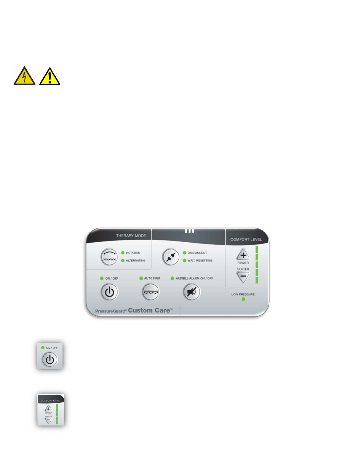
CONTROL UNIT FUNCTIONS:
ON/OFF: Ensure On/Off switch is “Off”. Plug power cord into wall outlet.
On/Off indicator light will illuminate in amber, indicating that the unit is
drawing current but not yet powered up.
Press On/Off switch to “ON”. Indicator light will change to green, along with
additional lights on control panel, indicating that the unit is powered up. Unit
will resume the settings it was in when last powered down.
COMFORT LEVEL: Initially set the “Comfort Level” on the control panel to
softest selection. Adjust for user comfort as desired, using “Softer” and “Firmer”
buttons.

9
P09588, Rev. 6 CO # 1848
NOTE: In powered mode, elevating the head of bed may require adjusting
comfort level to ensure appropriate support, especially if elevated beyond 30°
(see “Head of Bed Elevation”, below). With HOB elevated in this way, caregivers
may find the following body mass index (BMI) setting suggestions helpful in
determining an ideal comfort setting: Suggestions for comfort setting with HOB
elevated: BMI 12-20: setting 1; BMI 21-35: setting 2, BMI 36-50: setting 3;
BMI 51-70: setting 4; BMI 71-100: setting 5. A simple hand check can be used
to verify adequate seat support.
THERAPY MODE: Toggle between “Alternating” or “Rotation” mode as
desired.
The use of ROTATION should be viewed only as an adjunct to manual
repositioning of the patient for whom this repositioning is possible,
never as a replacement for it. “Frequent repositioning of the patient has
long been recommended as a means for preventing pressure ulcers.”¹
“All patients at risk for pressure ulcers continue to require regular
manual repositioning (turning), even those who are benefitting from the
use of a specialty lateral rotation surface”¹ Routine manual repositioning
should be used to provide opportunities for total offloading of pressure
from the sacrum, assessing the skin and maintaining proper alignment
and position on the support surface.
Note: when using wedges or pillows for manual repositioning (turning),
discontinue ROTATION and activate either FLOAT or ALTERNATING.
¹Krapfl, LA, Gray, M; Does Regular Repositioning Prevent Pressure
Ulcers? JWOCN. 2008; 35(6):571-57
LOW PRESSURE: If “Low Pressure” indicator light comes on after initial set-
up or when moving mattress or control unit, first check that all airlines are
properly connected and that they are not kinked. If light is still on after 30
minutes, call for service.
AUTO FIRM: Select the Auto Firm mode to stop the alternating or rotation
movement of the mattress. The AUTO FIRM indicator light will illuminate and
the mattress will achieve uniform support. The mattress will remain in the
Auto Firm mode for 20 minutes.
During this time, all five Comfort Level indicator lights will be illuminated in
amber, and the Comfort Level, Therapy Mode, Disconnect, and On/Off selectors
will be inactive. The Audible alarm is not affected.
After 20 minutes, the system will automatically resume the comfort and
therapy mode settings that had been previously selected.
Pressing the Auto Firm selector at any time prior to the elapsing of 20 minutes
will immediately return the system to the comfort and therapy mode settings it
was in prior to the pressing of AutoFirm.

10
P09588, Rev. 6 CO # 1848
AUDIBLE ALARM ON/OFF: When the “Alarm On” light is on, alarm will sound
if “Low Pressure” indicator light comes on. Press Alarm button to silence.
DISCONNECT / WAIT: RESETTING: The Disconnect function resets the
system to the ideal inflation level required for use of the mattress in the non-
powered therapy mode without an attached, powered control unit. To
maximize pressure redistribution, the disconnect procedure should be
performed at a time when no patient is on the mattress.
Press “Disconnect” button. Amber “Wait: Resetting” indicator will illuminate
while the mattress air system is being reset to the ideal inflation level.
During this time, the selector buttons and indicator lights of the Comfort Level,
Therapy Mode, Audible alarm, and Auto Firm will be inactive. The On/Off
selector will be also be inactive, but its green indicator light will remain active.
Pressing the “Disconnect” button again while the “Wait: Resetting” indicator
light is on will return unit to the settings it was in prior to the “Disconnect”
button being pressed.
Once the system has reached its ideal setting, the “Wait: Resetting” light will
turn off, replaced by the green “Disconnect” light. The green On/Off light will
change to amber, indicating that the unit is no longer powered up but is still
plugged in and drawing a current. The control unit can now be disconnected
from the mattress.
WARNING: Do not remove the control unit before it has properly re-set
the air system through use of the Disconnect function. Failure to wait for
completion of the disconnect function—or attempting to set the mattress
at a particular inflation level by disconnecting the control unit while it is
in another mode—can result in a pressure management profile that is
inappropriately high or low for a particular user. This could have
negative impact on pressure ulcer prevention, wound healing, and user
support.
NOTE: If circumstances make it necessary to disconnect the control unit before
the patient can be removed from the mattress:
•lower HOB to flat position
•ensure patient is in the center, supine position
•place the surface in “Autofirm” mode for 3-5 minutes prior to
performing the disconnect function.
While the resulting air level will be safe for non-powered use, the system may
not be at the ideal non-powered setting. Therefore, the control unit should be
reattached and the Disconnect procedure performed at the first opportunity
with the patient off the mattress.

11
P09588, Rev. 6 CO # 1848
Powered use: Other considerations
ELECTROMAGNETIC OR OTHER INTERFERENCE: This equipment generates, uses
and can radiate radio frequency energy and, if not installed and used in accordance with the
instructions, may cause harmful interference to other devices in the vicinity. However, there is
no guarantee that interference will not occur in a particular installation.
If this equipment does cause harmful interference to other devices, which can be determined by
turning the equipment off and on, the user is encouraged to try to correct the interference by one
or more of the following measures:
-Reorient or relocate the receiving device.
-Increase the separation between the equipment.
-Connect the equipment into an outlet on a circuit different from that to which the
other device(s) are connected.
-Consult the manufacturer for help.
See Additional Information, page 16.
POWER LOSS: In the case of a power outage, the system will equalize and maintain the air
within the support cylinders. When power is restored, control unit will resume the settings it
was in when power was interrupted.
PATIENT TRANSPORT: While transporting a patient on the mattress when the powered
mode has been in use, it is recommended to perform the disconnect function prior to powering
down the control unit. This will ensure that the system provides level, even support during
transport.
HEAD-OF-BED (H.O.B.) ELEVATION: All support surfaces using air as a support
medium are designed for distributing pressures over the body in a flat, horizontal position.
According to the guidelines of the National Pressure Ulcer Advisory Panel (NPUAP, caregivers
should limit the head-of-bed elevation to 30° or less for an individual on bed rest, unless
contraindicated by medical condition. Caregivers should encourage individuals to sleep in a 30
to 40° side-lying position or flat in bed if not contraindicated and avoid prolonged HOB elevation
that can result in a slouched position that places pressure and shear on the sacrum and coccyx.
Although the Custom Care Convertible will maintain its support and therapeutic capabilities up
to and including 70° HOB, in accordance with NPUAP guidelines any support surface should be
used with the head of the bed elevated as little as possible, and for limited periods at a time. If
HOB is elevated at 30° or beyond, a regular pattern of pressure relief in the form of a return to
non-elevated position is warranted. Adjustment of comfort level setting may also be required.
See “Comfort Setting”, above.
WARNING: To minimize the possibility of patient falls, lateral rotation
mode should not be used with head of bed elevated beyond 30°.
NOTE: In powered mode, elevating the head of bed may require adjusting comfort level to
ensure appropriate support, especially if elevated beyond 30°. Caregivers may find the following
body mass index (BMI) recommendations helpful in determining an ideal comfort setting: BMI
12-20: setting 1; BMI 21-35: setting 2, BMI 36-50: setting 3; BMI 51-70: setting 4; BMI 71-

12
P09588, Rev. 6 CO # 1848
100: setting 5.
TROUBLESHOOTING/PATIENT COMPLAINTS: Occasionally a patient may complain
of feeling as if he/she is “sinking into a hole”.
1) Sometimes this occurs when the head of the bed is elevated and the mattress is in either
lateral rotation or alternating pressure. This sensation is a combination of the deflation of the
cylinders during their cycle and the increased weight of the patient on the sacrum and pelvis
when the head of the bed is elevated. This demonstrates the need to minimize elevation of the
head of the bed, or to select alternating pressure mode if HOB elevation is necessary.
2) A patient may complain when he/she is supine or side-lying and are not used to the changing
pressures within the air system. Reassure the patient that this is normal functioning, as the
cylinders alternately inflate and vent. The vented tubes are not fully deflated. Some air is
always maintained in them to prevent bottoming out. After reassurance, patients typically
become acclimated to the changing pressures.

13
P09588, Rev. 6 CO # 1848
GENERAL DIRECTIONS
BED LINENS: Seven-inch deep fitted sheets are recommended. Multiple layering of linens or
underpads beneath the patient should be avoided for the prevention and treatment of pressure
ulcers.
CAUTION: Be careful not to puncture the mattress with needles or sharp
instruments. This may result in loss of integrity of the cover or internal air
system. Regularly inspect the mattress cover for cuts, rips, cracks or tears.
Do not use the mattress if the cover is damaged.
BED RAILS: Due to concerns over the possibility of patient entrapment, Span-America
recognizes that the use of rails of any length is a matter currently addressed by federal and state
laws/guidelines, and by individual facility protocol. It is the responsibility of the facility to be in
compliance with these laws, which typically require that decisions on the use of bed rails of any
type are based on assessment of the physical and mental status of each patient individually. If
bedrails are needed by the patient to prevent fall-related injury, as determined by this facility
assessment, we recommend that the bedrails be locked in the up position at all times. We do not
require use of bedrails unless the patient is deemed to be safer with them than without them.
CPR: The Standards for Life Support recommended by the American Heart Association suggests
a hard level surface for performing CPR. This means moving the person to the floor if possible.
If that is not possible, do the following: For performing CPR:
1. Press “Auto Firm” Button
2. Place a crash board beneath the patient.
3. Follow CPR procedures.
STORAGE AND TRANSPORTATION: Store the mattresses in a clean, dry place. Once the
mattress is removed from the box, store in a flat position if possible. Protect from damage.
Avoid temperature extremes (below freezing or above 120° F). Allow to acclimate to room
temperature before use. Do no stack more than 10 high. Do not stack other equipment on top of
the mattresses.
Store and transport controllers in a clean, dry place, protected from accidental damage or falls.
Avoid temperature extremes (below freezing or above 120°F); suggested storage and
transportation temperature 15~50°C, humidity 40%~80%. Do not stack other equipment on
top of the controller. For transportation, secure to prevent damage or falls. For shipment, use
box and packaging as provided by the manufacturer.
ENVIRONMENTAL CONDITIONS FOR USE:
•Indoor Use
•Altitude up to 2000 meters
•Temperature 5 °C to 35° C
•Maximum relative humidity 80% for temperatures up to 31° C, decreasing linearly by 50
per cent relative humidity at 40° C
•Mains Supply Voltage Fluctuation up to 10 +/-% of the nominal voltage
•Overvoltage Category II
•Pollution Degree 2

14
P09588, Rev. 6 CO # 1848
SERVICE: Return the control unit for repair or service to Span-America Medical Systems.
Repairs to be performed by manufacturer only.
Call 800-888-6752, 8 am – 5 pm EST M-F.
WARRANTY: The Custom Care is unconditionally guaranteed against failure due to
manufacturing defects under normal use for 24 months for the controller and 5 years for the
mattress. See page 22.
USE IN WOUND CARE: Use of PressureGuard®Custom Care models is only one element of care
in the prevention and treatment of pressure ulcers. Frequent repositioning, proper care, routine
skin assessment, wound treatment and proper nutrition are but a few of the elements required
in the prevention and treatment of pressure ulcers. As there are many factors that may influence
the development of a pressure ulcer for each individual, the ultimate responsibility in the
prevention and treatment of pressure ulcers is with the health care professional.
CLEANING: For the mattress, only the cover requires cleaning and maintenance. Disassembly of
the support surface for maintenance of internal components is not recommended. Clean and
disinfect mattress covers following contamination with bodily fluids and between patients.
The cover can be cleaned in place by wiping with neutral suds and lukewarm water. Rinse and
allow to air dry for approximately 20-30 minutes before use. For hard to clean spots, use liquid
cleaner with soft sponge in the concentration recommended by the manufacturer. DO NOT USE
HARSH CLEANERS OR SOLVENTS.
Reference the Cleaning Recommendations instruction sheet for additional cleaning
information.
For long-term incontinent applications, clean and disinfect cover daily. A scented cleaner/
disinfectant is recommended. Iodophor type disinfectants (e.g. Betadine) will stain the fabric.
For disinfection, phenolic or quaternary type disinfectants are recommended. Disinfectants
should be hospital grade (tuberculocidal). Follow manufacturer’s instructions for use
concentrations, contact times and rinsing.
Contamination with blood on the fabric can be disinfected with a 1:10 dilution of household
bleach (5.25% sodium hypochlorite) as recommended by the CDC. The use of bleach at improper
dilutions may result in fabric discoloration and fluid pass-through. Rinse and allow to air dry.
Where surveillance and epidemiology indicate ongoing transmission of C. difficile, an EPA
registered hypochlorite-based disinfectant is recommended. Follow the manufacturer’s
instructions for use concentrations, contact times and rinsing. Generic sources of hypochlorite
(e.g. household chlorine bleach) may also be used. Prepare the disinfection solution fresh daily at
a 1:10 dilution. Improper dilutions may result in ineffectiveness and higher than recommended
concentrations will damage the fabric.
Note: alcohol-based disinfectants are not effective against C. difficile and should not be used to
disinfect environmental services. For further information relative to this organism and infection
control in the healthcare setting, please refer to www.cdc.gov/ncidod/hip.
Do not puncture the mattress with needles or sharp instruments. This may result in loss of
integrity of the mattress air system or top surface low air loss bladder, and will void the
warranty. Inspect the covers and zipper area for signs of damage, puncture, or wear that could
result in fluid pass-through. If the cover is stained, soiled, or torn, inspect the internal
components for signs of contamination. If contamination is evident, quarantine the mattress and
remove from service following infection control procedures.
15
P09588, Rev. 6 CO # 1848
If required, the air control unit can be cleaned.
Turn unit off and unplug from wall before cleaning. [Note: The mattress will
maintain air with the unit unplugged. The unit will resume previous setting when
powered back up].
Wipe down using damp sponge or cloth that has been thoroughly wrung out to
remove excess liquid. Do not allow liquids to penetrate the user panel.
For cleaning, use neutral suds and lukewarm water. For disinfection, phenolic or quaternary
type disinfectants are recommended. Disinfectants should be hospital grade (tuberculocidal).
Follow manufacturer’s instructions for concentrations and contact times.
WASTE DISPOSAL: This Product has been supplied from an environmentally aware
manufacturer that complies with the WEEE.
This product may contain substances that could be harmful to the environment if disposed of in
locations (landfills) that are not appropriate according to legislation. Please be
environmentally responsible and recycle this product through your recycling facility at its end
of life.
AIR FILTER PREVENTIVE MAINTENANCE: The air filter for the Control Unit should be checked
routinely for signs of dirt or contamination. The frequency for cleaning depends on the air
quality. The air filter is accessible from the backside of the Control Unit. As the filter is white,
the need to clean is obvious. Simply turn the controller off and remove the plastic cover, remove
the filter, and hand wash using warm water and mild detergent. Rinse thoroughly and allow to
air dry. Replace the filter and the plastic cover.
ROUTINE INSPECTION OF POWER CORDS AND SAFETY TIPS TO PREVENT FIRES
1. Assure that the electrical resistance of the safety ground conductor and the level of
leakage current (line conductor-to-safety ground and neutral conductor-to-safety
ground) meet applicable standards for resistivity and leakage current. Protection
afforded by the ground pin is negated if the receptacle is not properly grounded. If you
have questions about the adequacy of your facility’s building wiring, contact qualified
electrician or consult the code authority in your jurisdiction.
2. Check all electrical outlets, including accessory outlets for cleanliness, physical integrity
and functionality. The IEEE standard 602-1996, section 4.2.2 advises that hospital-grade
outlets be used and that they should be mounted with the ground pin or neutral blade up
to assure that any metal that may drop between the plug and the wall will most likely
contact an unenergized blade.
3. Check the power cord to assure that contact pins are straight and secure.
4. Routinely inspect the power cord for damage sustained from crushing, pinching,
shearing, cutting, or from being worn through. They can be damaged by bed movement,
deterioration from use or aging, or human or equipment traffic. The cord’s insulation

16
P09588, Rev. 6 CO # 1848
should be intact and there should be no evidence of bulging, stretching, crimping,
cracking, or discoloration, especially at the ends, where the cord is attached to the plug
body and the control unit
5. Regularly inspect as parts of the bed frame, motor, mattress and controller, and the floor
beneath and near the bed for build-up of dust and lint.
6. Inspect the cover of the control panel to assure that the covering is not cracked or
damaged, allowing liquids or other conductive material to penetrate to the switches.
7. Report any unusual sounds, burning odors, or anything unusual to maintenance
personnel. Discontinue use of the power cord immediately and contact Span-America
Medical Systems for replacement.
Mattress
Inspect the covers and zipper area for signs of damage, puncture, or wear that could result in
fluid pass-through. If the cover is stained, soiled, or torn, inspect the internal components for
signs of contamination. If contamination is evident, quarantine the mattress and remove from
service following infection control procedures.
You may use the Preventive Maintenance Log provided on the last page (24) of this manual to
monitor and document regular inspection and maintenance of your PressureGuard Custom Care
Surfaces.
EMC
Electric devices may interact due to electro-magnetic radiation. We recommend a safety
distance of at least one –meter, especially for sensitive equipment.
Upon request, we will provide you with a table for more detailed information.
Guidance and manufacturer’s declaration – electromagnetic emissions
The 6500 is intended for use in the electromagnetic environment specified below. The customer or the user of the 6500
should assure that it is used in such an environment.
Emissions test
Compliance
Electromagnetic environment – guidance
RF emissions
CISPR 11 Group 1
The 6500 uses RF energy only for its internal
function. Therefore, its RF emissions are very
low and are not likely to cause any
interference in nearby electronic equipment.
RF emissions
CISPR 11
Class B
The 6500 is suitable for use in all
establishments, including domestic
establishments and those directly connected
to the public low-voltage power supply network
that supplies buildings used for domestic
purposes.
Harmonic emissions
IEC 61000-3-2
Class A
Voltage fluctuations/
flicker emissions
IEC 61000-3-3
Complies
Guidance and manufacturer’s declaration – electromagnetic immunity
The 6500 is intended for use in the electromagnetic environment specified below. The customer or the user of the 6500 should assure that it is used in such
an environment.
Immunity test
IEC 60601
test level
Compliance level
Electromagnetic environment – guidance
Electrostatic
discharge (ESD)
±6 kV contact ±6 kV contact Floors should be wood, concrete or ceramic tile. If floors are covered
with synthetic material, the relative humidity should be at least 30 %.
17
P09588, Rev. 6 CO # 1848
IEC 61000-4-2
±8 kV air
±8 kV air
Electrical fast
transient/burst
IEC 61000-4-4
±2 kV for power
supply lines
±1 kV for input/output
lines
±2 kV for power
supply lines
±1 kV for input/output
lines
Mains power quality should be that of a typical commercial or hospital
environment.
Surge
IEC 61000-4-5 ±1 kV line(s) to line(s)
±2 kV line(s) to earth
±1 kV line(s) to line(s)
±2 kV line(s) to earth
Mains power quality should be that of a typical commercial or hospital
environment.
interruptions and
voltage variations
on power supply
input lines
IEC 61000-4-11
<5 % UT
(>95 % dip in UT)
for 0,5 cycle
40 % UT
(60 % dip in UT)
for 5 cycles
70 % UT
(30 % dip in UT)
for 25 cycles
<5 % UT
(>95 % dip in UT)
for 5 sec
<5 % UT
(>95 % dip in UT)
for 0,5 cycle
40 % UT
(60 % dip in UT)
for 5 cycles
70 % UT
(30 % dip in UT)
for 25 cycles
<5 % UT
(>95 % dip in UT)
for 5 sec
Mains power quality should be that of a typical commercial or hospital
environment. If the user of the 6500] requires continued operation
during power mains interruptions, it is recommended that the 6500 be
powered from an uninterruptible power supply or a battery.
Power frequency
(50/60 Hz)
magnetic field
IEC 61000-4-8
3 A/m
3 A/m
Power frequency magnetic fields should be at levels characteristic of a
typical location in a typical commercial or hospital environment.
NOTE UT is the a.c. mains voltage prior to application of the test level.
Conducted RF
IEC 61000-4-6
Radiated RF
IEC 61000-4-3
3 Vrms
150 kHz to 80 MHz
3 V/m
80 MHz to 2,5 GHz
3 Vrms
3 V/m
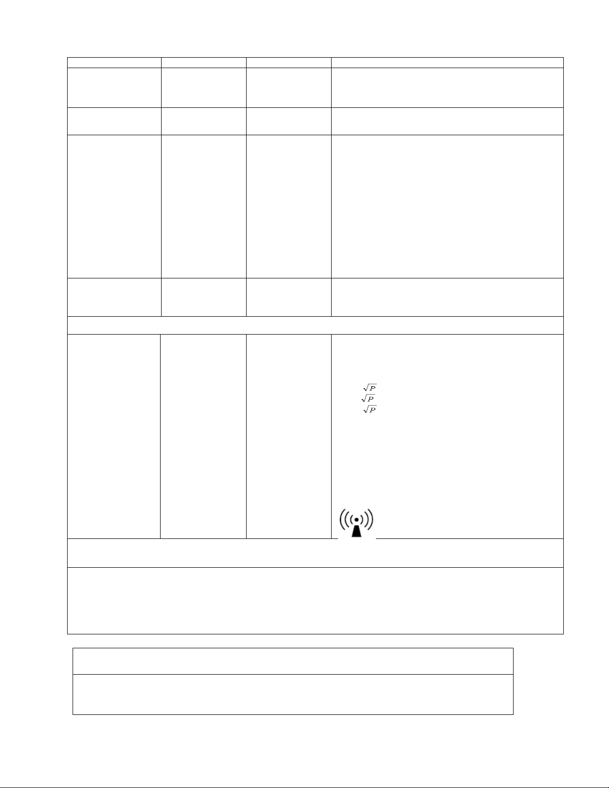
Portable and mobile RF communications equipment should be used no
closer to any part of the 6500, including cables, than the recommended
separation distance calculated from the equation applicable to the
frequency of the transmitter.
Recommended separation distance
d = 1,2
d = 1,2 80 MHz to 800 MHz
d = 2,3 800 MHz to 2,5 GHz
where P is the maximum output power rating of the transmitter in watts
(W) according to the transmitter manufacturer and d is the
recommended separation distance in metres (m).
Field strengths from fixed RF transmitters, as determined by an
electromagnetic site survey,a should be less than the compliance level
in each frequency range.b
Interference mayoccur in the vicinity of equipment marked with the
following symbol:
NOTE 1 At 80 MHz and 800 MHz, the higher frequency range applies.
NOTE 2 These guidelines may not apply in all situations. Electromagnetic propagation is affected by absorption
and reflection from structures, objects and people.
a Field strengths from fixed transmitters, such as base stations for radio (cellular/cordless) telephones and land mobile radios, amateur radio, AM and FM
radio broadcast and TV broadcast cannot be predicted theoretically with accuracy. To assess the electromagnetic environment due to fixed RF
transmitters, an electromagnetic site survey should be considered. If the measured field strength in the location in which the 6500 is used exceeds the
applicable RF compliance level above, the 6500 should be observed to verify normal operation. If abnormal performance is observed, additional
measures may be necessary, such as reorienting or relocating the 6500.
b Over the frequency range 150 kHz to 80 MHz, field strengths should be less than 3 V/m.
Recommended separation distances between
portable and mobile RF communications equipment and the 6500
The 6500 is intended for use in an electromagnetic environment in which radiated RF disturbances are controlled. The
customer or the user of the 6500 can help prevent electromagnetic interference by maintaining a minimum distance
between portable and mobile RF communications equipment (transmitters) and the 6500 as recommended below,
according to the maximum output power of the communications equipment.
Table of contents
Other SPAN Medical Equipment manuals


Popular Medical Equipment manuals by other brands


Getinge
Getinge Arjohuntleigh Nimbus 3 Professional Instructions for use

Mettler Electronics
Mettler Electronics Sonicator 730 Maintenance manual

Pressalit Care
Pressalit Care R1100 Mounting instruction

Denas MS
Denas MS DENAS-T operating manual

bort medical
bort medical ActiveColor quick guide

AccuVein
AccuVein AV400 user manual


