SPAN PressureGuard EASY AIR LR User manual
OWNER’S MANUAL
PressureGuard®
Easy Air®LR


3
P11544 R3 CO#2643
TABLE OF CONTENTS
DOCUMENT SYMBOLS........................................................................................... 4
INTRODUCTION ..................................................................................................... 6
INDICATIONS FOR USE
GENERAL DESCRIPTION
MODES OF OPERATION
PRODUCT DESCRIPTION ........................................................................................ 7
THE SCIENCE BEHIND THE EASY AIR MICROCLIMATE MANAGEMENT DESIGN... 10
MATTRESS AND CONTROL UNIT SETUP DIRECTIONS .......................................... 11
ELECTROMAGNETIC OR OTHER INTERFERENCE .................................................. 13
CONTROL UNIT FUNCTIONS ................................................................................ 20
GENERAL DIRECTIONS FOR USE
ELEVATING HEAD OF BED.................................................................................... 23
BED RAILS ............................................................................................................ 23
CPR ...................................................................................................................... 23
PATIENT TRANSPORT .......................................................................................... 24
POWER LOSS ....................................................................................................... 24
BED LINENS.......................................................................................................... 24
INCONTINENCE PADS .......................................................................................... 24
SERVICE ............................................................................................................... 24
ENVIRONMENTAL CONDITIONS FOR USE............................................................ 25
STORAGE AND TRANSPORTATION ...................................................................... 25
CLEANING
MATTRESS COVERS ............................................................................................. 26
AIR CONTROL UNIT.............................................................................................. 27
PREVENTIVE MAINTENANCE
FILTER MAINTENANCE......................................................................................... 28
POWER CORDS .................................................................................................... 29
MATTRESS ........................................................................................................... 30
SPECIFICATIONS .................................................................................................. 32
ORDERING INFORMATION .................................................................................. 35
TROUBLE SHOOTING GUIDE................................................................................ 38
APPENDIX: PREVENTIVE MAINTENANCE LOG ..................................................... 42
4
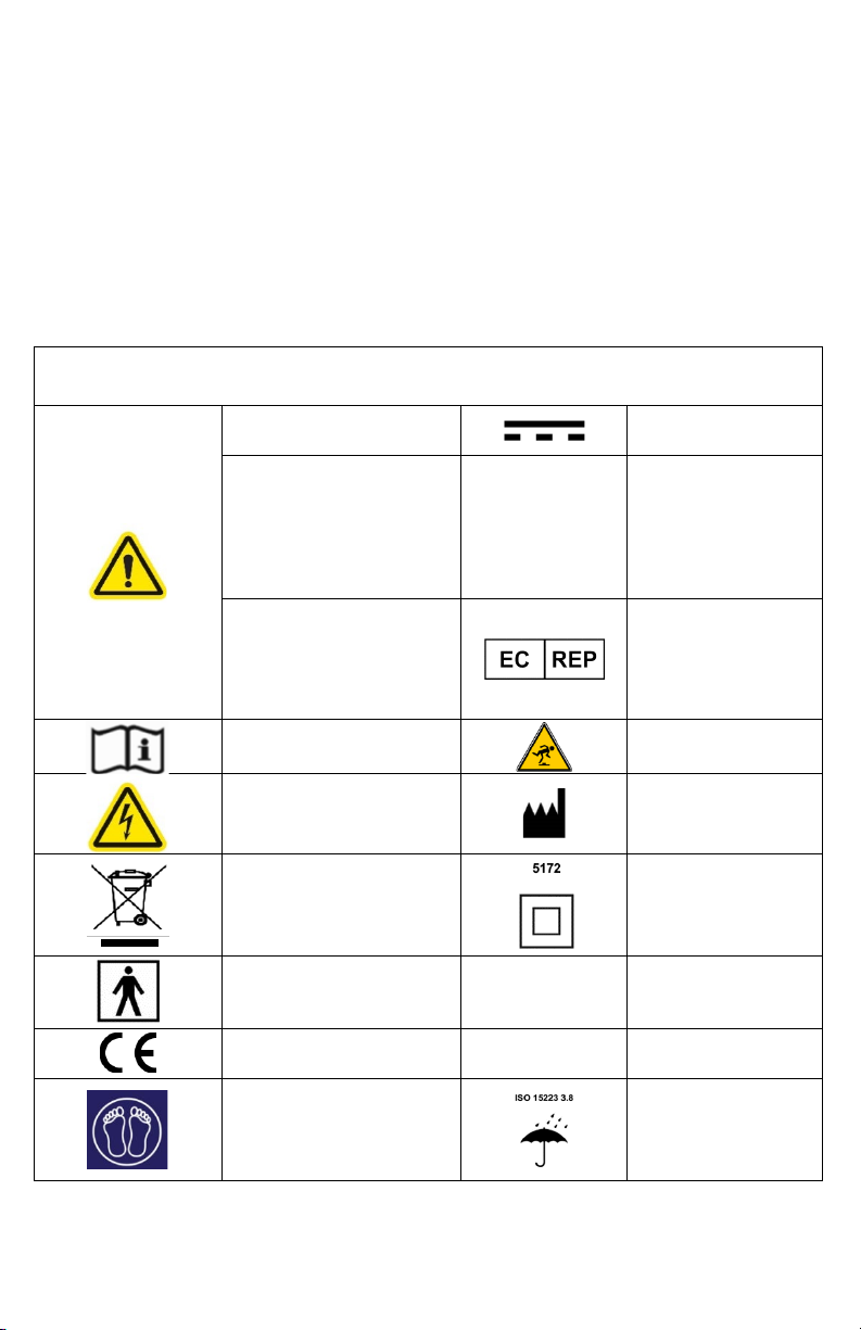
DOCUMENT SYMBOLS
This manual contains different typefaces and symbols to make
the content easier to read and understand:
•Standard text – used for regular information.
•Boldface text – stresses a word or phrase.
•NOTE: - sets apart special information or important
instruction clarification.
Document Symbols
WARNING or CAUTION Direct Current
WARNING: Situations or
actions that may have an
effect on patient or user
safety. Ignoring a warning
could cause patient or user
injury.
IP21
Protection against
the ingress of fingers
or similar objects and
dripping water
CAUTION: Points out
special procedures or
precautions that persons
must obey to avoid
equipment damage.
Authorized
Representative in the
European
Community
See the user manual for
use instructions
Potential trip hazards
Electrical shock hazard
warning Manufacturer
WEEE
Double Insulated
system
Type BF applied part EN 60601-1-2 Electromagnetic
Emissions
European Conformity
Marking
IEC 60601-1
60601-1-11
Electrical Safety
Home Healthcare
Foot End
Keep Dry or Do Not
Wet
5
P11544 R3 CO#2643
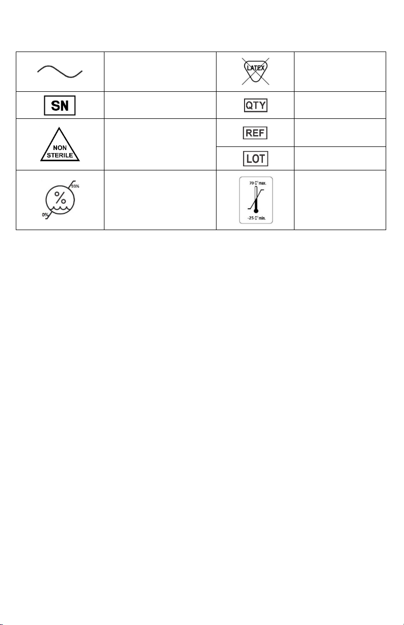
Alternating current
Not made with
natural rubber latex
Serial number Quantity
Non Sterile
Catalogue
Number
Batch Code
Humidity limitation
Temperature
limitation
Table of contents
Other SPAN Medical Equipment manuals


Popular Medical Equipment manuals by other brands


Getinge
Getinge Arjohuntleigh Nimbus 3 Professional Instructions for use

Mettler Electronics
Mettler Electronics Sonicator 730 Maintenance manual

Pressalit Care
Pressalit Care R1100 Mounting instruction

Denas MS
Denas MS DENAS-T operating manual

bort medical
bort medical ActiveColor quick guide

AccuVein
AccuVein AV400 user manual


