Spartan Ultimaster Purolator User manual

NST13165-2_A 2019-02-12 Page 1
KEYLESS ENTRY
SECURITY SYSTEM
16517738
SERVICE MANUAL

X
NST13165-2_A 2019-02-12 Page 2
OPERATION
KEYLESS ENTRY OPERATION LE
USING KEYCHAIN TAG
Present (swipe) Keychain Tag to antenna reader located near door to be unlocked. Tag should
be swiped within 3-4 inches of antenna reader.
• Door should unlock.
• After six (6) seconds the door will automatically re-lock whether it is opened or closed.
Note: After tag has been swiped three (3) times in succession, the system will not allow another
swipe for 20 seconds.
USING SWITCH
Press and release switch located near door to be unlocked (switch is momentary switch).
• Door should unlock immediately.
• After six (6) seconds the door will automatically re-lock whether it is opened or closed.
Keychain Tag
16517728
Antenna Reader
16517737
Note Tag can ONLY be enrolled at Curbside antenna location
Press switch at Bulkhead location five times.
- All tags are unenrolled (single tags cannot be unenrolled).
Press switch at Curbside location five times.
- Antenna Red LED flashes for 20 seconds.
During this flash time, swipe tag at antenna.
- Antenna Red LED double flashes indicting tag enrolled
TAG ENROLLMENT
TAG UNENROLLMENT

X
NST13165-2_A 2019-02-12 Page 3
MOD-QC TEST INPUTS - ALL DOORS SHOULD BE CLOSED
Any time the Antenna/Reader is powered-up, the Mod-QC Test is executed and takes about
30-seconds. The red and green status LEDs emit a series of flashes which indicate the status of the
inputs to the Antenna/Reader. The Mod-QC Test interrogates the Antenna/Reader location inputs, the
data bus input and the inputs to the unlock switch and the RFID circuit. The Curbside door is the
Master Node which controls ALL of the data traffic.
DOOR LOCATION - First QC Test (5-10 Seconds)
Note: the red LED will flash the location sequence twice
Curbside Door 1-flash or single flash
Bulkhead Door 3-flashes or triple flash
Rear Door 4-flashes or quad flash
DATA BUS - Second QC Test (10 Seconds)
If the data bus on the Bulkhead and Rear door Antenna/Readers is communicating with the Curbside
door (the master node), the red LED will flicker-flash for 10-seconds. If you are testing the Curbside
door, the red LED will flicker-flash for about 3-seconds then be off for about 7-seconds.
INPUTS - Third QC Test (15 Seconds)
In this test, each of the inputs is tested: the RFID circuit and the unlock switch input.
RFID
Present any RFID key (Keychain Tag) to the Antenna/Reader. It does not need to be enrolled.
When any Tag is detected, both LEDs will turn off and back on when the Tag is removed.
UNLOCK SWITCH
Press the unlock switch. If the unlock switch input is detected, the green LED will turn off and
back on when the switch is released.
KEYLESS ENTRY

X
NST13165-2_A 2019-02-12 Page 4
REAR Roll Up DOOR
Purolator
Solenoid
Switch
Antenna
Chassis GND
Chassis GND
Chassis GND
Solenoid
Switch
Antenna
Connect to Truck
Wire Harness
16517730
HNS13111-2
BLUE
16517732
HNS13111-4
Lt. Blue
16517729
HNS13111-1
BLUE
16517731-14 (14 ft.)
HNS13111-14
Magenta
16517731-16 (16 ft.)
HNS13111-16
16517731-18 (18 ft.)
HNS13111-18
16517733
HNS13111-5
Red
SYSTEM DIAGRAM

NST13165-2_A 2019-02-12 Page 5
BLOCK DIAGRAM
(+) (-)
BATTERY
A B C D
A B C D
X X X
X X X
SW Part #
Right Side
C/S Switch
1
2
3
4
X
COWL HNS
16517729
GN/YL
WT
RD
1
2
3
4
1 2 3 4
5 6 7 8
X
XX
1 2 3 4
5 6 7 8
RIGHT SIDE
C/S ANTENNA
/ READER
- MASTER
RIGHT SIDE
C/S SOLENOID
PASS SIDE HNS
16517730
1
2
1
2
1 2 3 4
5 6 7 8
BULKHEAD
BK ANTENNA
/ READER
NOTE 2
1 2 3 4
5 6 7 8
REAR DOOR
RR ANTENNA
/ READER
NODE 3
1
2
3
1
2
3
1
2
3
1
2
3
10A AT
FUSE
PANEL
1 2 3 4
5 6 7 8
1 2 3 4
5 6 7 8
BULKHEAD
BK SOLENOID
1
2
1
2REAR DOOR
RR SOLENOID
1
2
1
2
SW Part#
Bulkhead
BK Switch
1
2
3
SW Part #
Rear Door
RR Switch
1
2
3
X
XX
X
ROOF EXT HNS
16517731-14 (14 ft)
16517731-16 (16 ft)
16517731-18 (18 ft)
REAR DOOR HNS
16517733
DK GN
LB
WT
GN/YL
TN
RD
WT
WT
TN
RD
OR
PK/YL
WT
PK
WT
TN
RD
WT
TN
RD
BULKHEAD HNS
16517732
CHASSIS
GROUND
16517738 16517738 16517738
Keychain
Tag
16517737
Keychain
Tag
16517737
Keychain
Tag
16517737

NST13165-2_A 2019-02-12 Page 6
TROUBLESHOOTING
SYMPTOM - KEYLESS ENTRY
DOOR DOES NOT UNLOCK ANTENNA / READER
1 Door Does Not Unlock When a Keychain Tag is Swiped
POSSIBLE CAUSE
CORRECTIVE ACTION
1.1.3
Enroll new Keychain Tag - See Code Enrollment
section. (Page 2)
1.1
Keychain Tag is not enrolled correctly
Note: Door unlocks when unlock
switch is pressed.
1.2
The Keychain Tag is damaged or
defective
1.2.1
If the door will unlock using the switch, but
will not unlock with the Keychain Tag, then
the Keychain Tag is defective. Replace the
Keychain Tag and enroll it. See Code
Enrollment section (Page 2).
1.3
The Antenna/Reader RFID circuit has
failed
1.4
Wire Harness, crimp, ground
connection or solenoid had failed
1.3.1
Unplug the Antenna/Reader from the
wire harness and recoonnect it. Obseve
the Mod-QC Test. First, the location code
will be flashed. Second, the data
bus operation is tested. Third, both LEDs will turn on
solid for 15-seconds to check the Antenna/Reader
RFID circuit. Present a Keychain Tag. If the Keychain
Tag is detected, both LEDs turn off and back on; the
Antenna/Reader RFID circuit is OK. If the Tag is not
detected, the RFID circuit is failed. Replace the
Antenna/Reader.
1.4.1
If the red LED flashes when swiped
with the Keychain Tag or the Unlock
switch is pressed, but the door does
not unlock, check the truck harness
and connector. The solenoid output
voltage on pin #3 (gray wire) should
be +12V any time the green LED is on for 6-seconds.
If +12V is present on pin #3 (gray wire), check the
truck wire harness and the ground and solenoid
connections. Repair as needed.
1.1.1
Swipe Antenna/Reader with Keychain
Tag - Does red LED on Antenna/Reader
flash twice? If yes, Keychain Tag is
enrolled correctly.
1.1.2
If no, press the unlock switch to verify the
Antenna/Reader and solenoid are operating correctly.
The red LED should flash once when the unlock switch
is pressed and the door should unlock.
Antenna/Reader
Connector
Pigtail

NST13165-2_A 2019-02-12 Page 7
TROUBLESHOOTING
SYMPTOM - KEYLESS ENTRY
2 Door Does Not Unlock When Pressing the Unlock Switch
POSSIBLE CAUSE
CORRECTIVE ACTION
2.1.1
Try unlocking the door using
the Keychain Tag. If the door
unlocks, the unlock switch or
wire harness is defective.
2.1
The unlock switch is damaged or defective
Note: Door does unlock when swiped
2.2
The harness connection between the
switch and the Antenna/Reader has
failed
2.3
The connector or terminal crimps have
failed
2.2.2
If the switch is OK, check the wire harness and
connectors and repair as needed.
2.3.2
If the Antenna/Reader red LED does not
flash and you have verified there is an
input on pin #5 when the switch is
pressed, then replace the antenna.
Verify that a ground signal is present at the switch on
the #2 COM terminal when the switch is NOT pressed
to check the wire harness connection.
2.1.2
If there is a ground signal present on the
#2 COM terminal, press the switch and
check for ground on the normally open
(NO) terminal. If ground is not detected
on both terminals, the switch is
defective.
2.2.1
If the switch is OK, check the input pin on
the Anntenna/Reader connector, pin #5.
There should be a ground on this terminal
when the switch is pressed. If there is no
ground, correct or replace the harness.
2.3.1
Using a ground input, touch pin #5 on the
Antenna/Reader connector. If the red LED flashes
once and the door unlocks, the Antenna/Reader and
connector are OK. Locate the connector or crimp
problem and repair or replace the wire harness.

NST13165-2_A 2019-02-12 Page 8
TROUBLESHOOTING
SYMPTOM - KEYLESS ENTRY
3 Door Does Not Unlock When Keychain Tag Is Swiped or Unlock Switch is Pressed,
But the Green LED Turns On for 6-Seconds
POSSIBLE CAUSE
CORRECTIVE ACTION
3.1.1
Using a voltmeter, check the ground wire to the
solenoid and verify it is making good contact with the
truck chassis ground. If there is no ground, correct the
ground connection.
3.1
The solenoid does not have a ground
connection
3.2
No power to the solenoid
3.3
Solenoid rod is jammed
3.4
Door is jammed
3.5
There is a short in the wire harness or
solenoid
3.6
There is an internal short in the
Antenna/Reader
Using a volmeter, verify there is +12V
on pin #1 red wire), then check for
+12V on pin #3 (gray wire) of the
Antenna/Reader connector when
the green LED is on. If there is no +12V, check the
connector to make sure a crimp or pin is not damaged.
If the harness and crimps are OK, replace the
Anetnna/Reader.
3.2.2
If there is +12V on the Antenna/Reader connector
when the LED is green, check +12V on the solenoid. If
there is no +12V at the solenoid, repair the wire
harness.
3.3.1
If there is power and ground at the correct pins to the
solenoid, check the solenoid itself. if the solenoid rod
does not move when the solenoid or door locking
mechanism is energized, either the solenoid is jammed
or defective. Repair or replace the solenoid.
3.4.1
If the Antenna/Reader and solenoid appear to be
working corrrectly, check the door’s alignment. Adjust
the door as required to operate properly.
3.6.1
If you have verified there is no short in the wire
harness, connection or solenoid, AND YOU
HAVE RESET POWER TO THE
ANTENNA/READER, then the Antenna/Reader
is defective. Replace the Antenna/Reader.
*Note: “Smart switches” with internal circuit breakers protect the
outputs. When the short is corrected, the smart switch must be
reset. To reset the Antenna/Reader, swipe it using the Keychain
Tag or unplug the unit to reset the circuit. There is NO visual
indication that the internal circuit protection has been tripped.
3.2.1
3.5.1
The internal circuit breaker in the
Antenna/Reader module will detect a short in
the wire harness, connector or solenoid.
Locate the short and repair it. Reset the
system by swiping the Antenna/Reader or
pressing the unlock switch (see note below*).

NST13165-2_A 2019-02-12 Page 9
TROUBLESHOOTING
SYMPTOM - KEYLESS ENTRY
4 Unlock Response Is Slow When Keychain Tag is Swiped
POSSIBLE CAUSE
CORRECTIVE ACTION
4.1.1
Determine if there is a failure in the ID location pins in
one of the Antenna/Readers and there is a “location
conflict” on the data bus. For example, the ground
input on pin #7 has failed (no ground) and the system
thinks there are two Master (Curbside) nodes present.
The Master node is the Curbside which controls the
data bus traffic. Unplug each Antenna/Reader and
observe the Mod-QC test. If the first test, which
identifies the Antenna/Reader location, indicates two
units with the same location ID, then you have found
the problem. Fix the connector or wire harness.
4.1
Data bus has failed due to wire harness or
connector problem
4.2
There is an internal short in the
Antenna/Reader causing a data bus issue
4.2.1
If you have verified there is no wire harness or
connector problem and all of the Antenna/Reader
locations are correctly identified, unplug the
Antenna/Reader from the wire harness and reconnect
it. Observe the Mod-QC Test. First the location code
will be flashed twice. Second, the data bus operation is
tested and if the data bus is present, the red LED will
flicker-flash 10-seconds (if the Antenna/Reader is at
the Curbside door, the flicker-flash is a short 3-second
burst). If the red LED does not flicker-flash, the data
bus circuit has failed. Replace the Antenna/Reader.
SYMPTOM - DATA BUS
1 Red Status LED on Antenna/Reader Flashes @ 1-Sec Rate When Door Unlocked -
Indicates a Data Bus Failure
POSSIBLE CAUSE
CORRECTIVE ACTION
1.1.1
If the harness is not shorted to power, disconnect the
wire harness connector for power and ground located
under the hood. Check different points in the wire
harness and see if the chassis ground is present. With
the wire harness disconnected from the truck, there
should be NO chassis ground detected. if there is a
ground detected, locate the problem and repair it.
1.1
There is a short in the wire harness
between the Antenna/Reader’s tan, red or
black wires
1.1.2
If the harness is not shorted to power or chassis
ground, it can be shorted to the ground or power wire
in the harness. With the harness disconnected from the
battery, check for +12V and ground between the power
and ground wires in the harness. If +12V or ground is
connected to the data wire (tan), locate the problem
and repair it.
NST13165-2_A 2019-02-12 Page 10
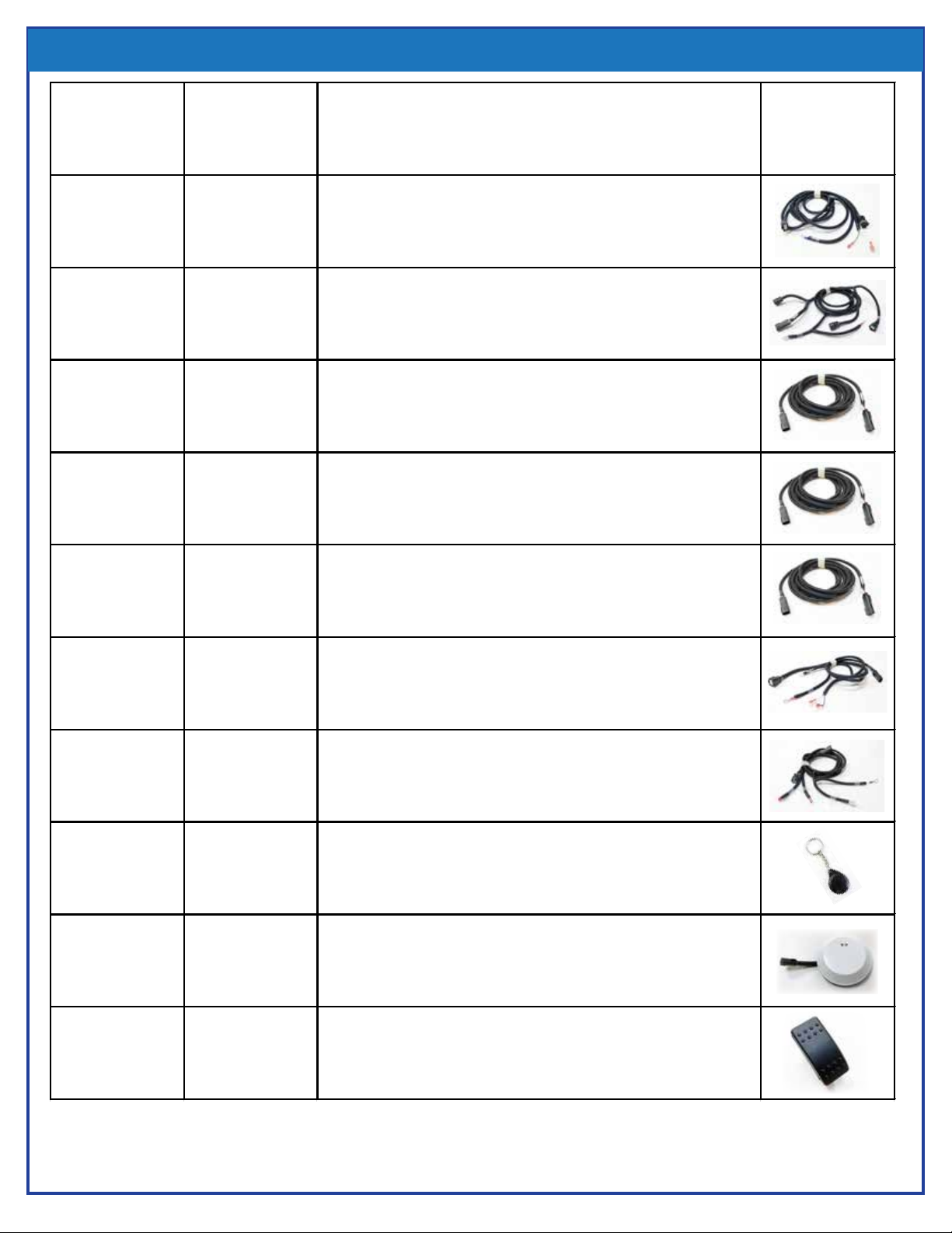
SERVICE PARTS
Utilimaster
Part #
TouchTronics
Part # Description
16517729 HNS13111-1 Cowl Harnesses
16517730 HNS13111-2 Passenger Side Door Harness
16517731-14 HNS13111-14 Roof Extension Harness - 14 feet
16517731-16 HNS13111-16 Roof Extensin Harness - 16 feet
16517731-18 HNS13111-18 Roof Extension Harness - 18 feet
16517732 HNS13111-4 Bulkhead Door Harness
16517733 HNS13111-5 Rear Door Harness
16517737 M125-7737 Keychain Tag
16517738 M110-7738 Antenna/Reader
_ SWS12112-9 Rocker Switch, Momentary ON-OFF, SPST

NST13165-2_A 2019-02-12 Page 11
NOTES

NST13165-2_A 2019-02-12 Page 12
57315 Nagy Dr
Elkhart, IN 46517
800-294-2570
574-294-2570
www.touchtronics.com
© 2006 TouchTronics, Inc. All Rights Reserved. TouchTronics, the TouchTronics logo, and other
TouchTronics marks are owned by TouchTronics and may be registered. TouchTronics assumes no
responsibility for any errors that may appear in this manual. Information contained herein is subject
to change without notice.
FCC Compliance and Advisory Statement. This hardware device complies with Part 15 of the FCC
Rules. Operation is subject to the following two conditions: 1) this device may not cause harmful
interference, and 2) this device must accept any interference received, including interference that
may cause undesired operation. Any changes or modifications not expressly approved by the party
responsible for compliance could void the user’s authority to operate the equipment.
Canadian Compliance Satement. This device complies with RSS-210 of Industry Canada.
Operation is subject to the following two conditions: 1) this device may not cause interference, and
2) this device must accept any interference, including interference that may cause undesired
operation of the device.
© 2006 TouchTronics, Inc. Tous droits réservés.TouchTronics, le logo TouchTronics et les autres
marques TouchTronics sont la propriété exclusive de TouchTronics et sont susceptibles dêtre des
marques déposées. Toutes les autres marques sont la propriété exclusive de leurs détenteurs
respectifs. TouchTronics décline toute responsabilité en cas derreurs dans ce manuel. Les
informations énoncées dans le présent document peuvent faire lobjet de modifications sans avis
préalable.
Déclaration FCC. Cet équipement a été testé et déclaré conforme à la section 15 du règlement de
la FCC. Son fonctionnement est soumis aux conditions suivantes: 1) léquipement concerné ne doit
pas causer dinterférences dangereuses, et 2) il doit accepter toute interférence reçue, y compris les
interférences risquant dengendrer unfonctionnement indésirable. Toutes modifications ou tous
changements effectués sans laccord exprès de la partie responsable de la conformité aux normes
pourraient contraindre lutilisateur à ne plus utiliser son équipement.
Déclaration du Ministère des Communications Canadien. Cet équipement a été déclaré conforme à
la norme RSS-210 édictée par le Ministère canadien de lindustrie. Son fonctionnement est soumis
aux conditions suivantes: 1) léquipement concerné ne doit pas causer dinterférences, et 2) il doit
accepter toute interférence reçue, y compris les interférences risquant dengendrer un
fonctionnement indésirable.
FCC COMPLIANCE
Table of contents
Popular Remote Starter manuals by other brands


Audiovox
Audiovox Pursuit PRO 9232 owner's manual

ADS
ADS iDatastart HC1151A Product guide

CrimeStopper
CrimeStopper Cool Start RS-1300DP installation instructions

Audiovox
Audiovox AS-9055 installation instructions

ENDEAVOUR
ENDEAVOUR ET6795 instruction manual

Young Shin Electronics
Young Shin Electronics R1800-900FM user guide

Audiovox
Audiovox PURSUIT PRO-9056i installation manual

Energizer
Energizer ENX12K user manual

ULTIMATE SPEED
ULTIMATE SPEED UMAP 12000 B2 Operation and safety notes

Schumacher
Schumacher Instant Power IP-125 owner's manual

Audiovox
Audiovox PRO9555 owner's manual

Alpha tools
Alpha tools A-ES 1700/1 Original operating instructions