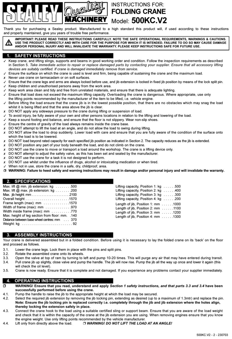
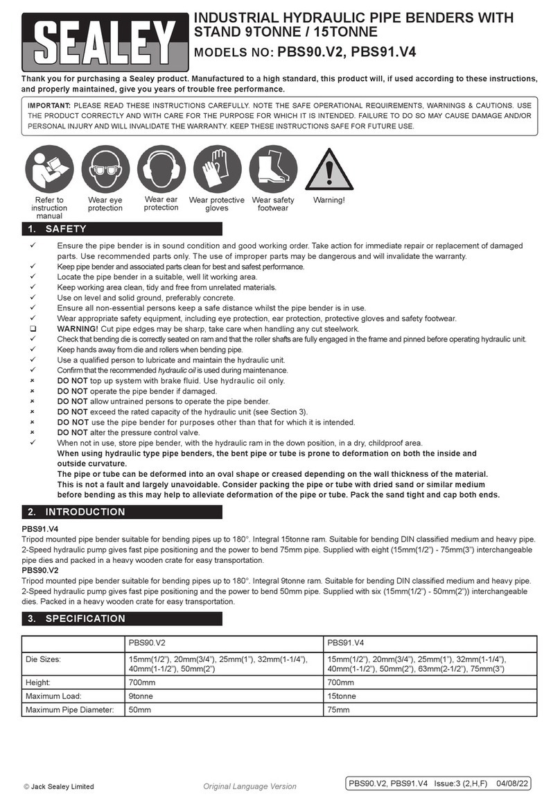
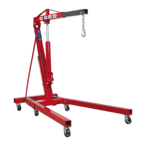
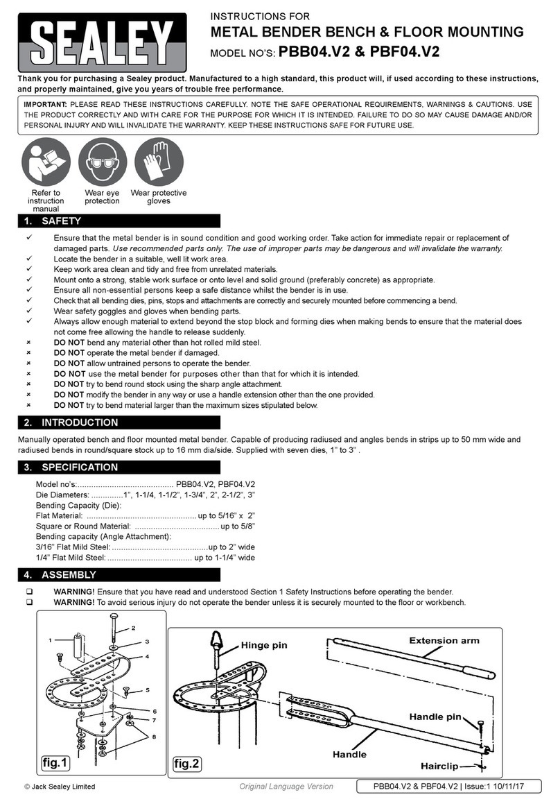
Sealey Quality MACHINERY WD302 User manual

Page 1 WD302 - 2 - 050308
INSTRUCTIONS FOR: FIXED FRAME CRANE
MODEL NO: WD302.
Thank you for purchasing a Sealey product. Manufactured to a high standard this product will, if used according to these instructions
and properly maintained, give you years of trouble free performance.
IMPORTANT: PLEASE READ THESE INSTRUCTIONS CAREFULLY. NOTE THE SAFE OPERATIONAL REQUIREMENTS, WARNINGS & CAUTIONS.
USE THE PRODUCT CORRECTLY AND WITH CARE FOR THE PURPOSE FOR WHICH IT IS INTENDED. FAILURE TO DO SO MAY CAUSE
DAMAGE OR PERSONAL INJURY AND WILL INVALIDATE THE WARRANTY. PLEASE KEEP INSTRUCTIONS SAFE FOR FUTURE USE.
2. GENERAL
1. CONTENTS
Section 2. General. ....................................1.
Section 2.1 Identification .................................1.
Section 2.2. Technical Data. ...............................1.
Section 3. Safety/Operational Instructions. ..................2.
Section 4. Maintenance/Examination/Inspection. .............2.
Section 5. Assembly/storage and priming. ..................3.
Section 6. Owner’s & Operator’s Responsibilities .............3.
Section 7. Declaration of Conformity. ......................4.
Section 8. Parts List/Diagram ............................5.
Page No.
2.1. Identification
Supplier: Sealey Power Products,
Kempson Way,
Suffolk Business Park,
Bury St Edmunds,
Suffolk, IP32 7AR.
Model No: WD302
2.2. Technical Data
Rated Capacity
Safe Working Load (SWL) 3t (tested to 50% overload).
Working Load Limit (WLL) 3t (tested to 50% overload).
Lifting Cap. in Position 1: ..............3000kg
Lifting Cap. in Position 2: ..............2500kg
Lifting Cap. in Position 3: ..............2300kg
Maximum Lift Ht. at Minimum Jib Extn: ...2760mm
Maximum Lift Ht. at Maximum Jib Extn: ...2920mm
Length of Jib Position 1: ...............1620mm
Length of Jib Position 2: ...............1765mm
Length of Jib Position 3: ...............1910mm
Height of Frame: .....................265mm
Length of Frame: ....................2150mm
Overall Height: ......................2000mm
Maximum Width of Frame: .............1290mm
Width Inside Frame: ..................1120mm
Weight: ............................302kg
a) Design Capability: Test Load 50% overload.
b) For a description of in-service and out-of-service conditions see
section 3 Safety, Section 4 Maintenance and Section 6.
c) The crane is fitted with a bypass valve that will prevent the ram
from over extending.
d) For applications see Section 3 Safety.
e) For control system, see Fig.1 for release valve and pump handle
assy. Usage is explained in Section 3.2 Operation.
f) For ground condition requirements, see Section 3 Safety.
g) For information on parts and materials requiring specialised
repair techniques see Section 4 Maintenance.
fig.1
RELEASE
VALVE
PUMP
HANDLE
ASSY.
1910mm
1765mm
2920mm
2840mm
1290mm
1120mm
265mm
2000mm
2760mm
1620mm
2150mm
3000kg Max.
2500kg Max.
2300kg Max.

Page 2 WD302 - 2 - 050308
3. SAFETY/OPERATING INSTRUCTIONS
3.2. OPERATION. (Refer to Section 4.2 (a) regarding inspection before each and every use). (No's refer to Parts Diagram Page 5).
a) Refer to the lifting capacity chart in Section 2.2 (Technical Data). If necessary adjust the position of the jib extension to cater for the weight
that is to be lifted. To adjust the jib extension remove the clip (50) and pin (49) and slide the jib in or out as required to the next position.
Replace the clip and pin in the new position. Close the release valve by turning knob (12) clockwise (see fig.1)
b) Screw the pump handle into either of the two available pumping positions and commence pumping to raise the jib to the height at
which the load will be secured.
c) Connect the crane hook to the load using a suitable certified sling or support beam. When removing engines use only lifting points
recommended by the vehicle manufacturer.
d) Lift only directly above the load. WARNING! DO NOT LIFT THE LOAD AT AN ANGLE!
e) To lower the load turn the release valve knob slowly anticlockwise. The load will descend at a controlled rate and can be stopped by
turning the knob clockwise to close the valve.
f) The crane is not a transportation device but may be used to reposition the load ready for working on. To do so, lower the load and jib
to the lowest possible point before attempting to move. Do not attempt to move in a sideways direction.
The crane is not designed to sustain the load indefinitely. When you have positioned the load for working, fully lower the load onto a
secure and appropriate working base, being fully aware of your own and other persons location in relation to the lowering load.
g) When the load has been successfully lowered and secured, remove the securing harnesses etc. and place the crane in an appropriately
safe location having ensured the jib is fully lowered.
NOTE: ENSURE YOU HAVE READ AND UNDERSTOOD THE SAFETY INSTRUCTIONS AT THE BEGINNING OF THIS SECTION BEFORE YOU
OPERATE THE CRANE.
3.1. SAFETY
✓Keep crane, lifting slings, support and beams in good working order and condition. Follow the inspection requirements as
described in Section 4 page 2 Maintenance. Take immediate action to repair or replace damaged parts by contacting your
supplier. Ensure that all accessory lifting devices are suitably certified. If crane is damaged, remove from service immediately.
✓ Ensure the surface on which the crane is used is level, firm and capable of supporting the weight of the crane with maximum
load - we recommend concrete. Never use the crane on tarmacadam or other soft surfaces.
✓ Ensure the crane legs and arms are locked before use.
✓ Keep children and unauthorised persons away from the working area.
✓ Keep working area clean and tidy, free from unrelated materials and ensure that there is adequate lighting.
✓ Ensure that load does not exceed the maximum lifting capacity of the crane. Overloading the crane is dangerous. Where
appropriate, use only the lifting points recommended by the manufacturer of the item to be lifted, e.g. vehicle engine.
✓ Before lifting the load ensure that the crane jib is in the lowest practical position, that there are no obstacles which may snag
the load whilst it is being lifted and that the area above the jib is clear.
✓ To avoid injury, be fully aware of your own and other persons locations in relation to the lifting, and lowering, of the load.
✓ Keep a sound footing and ensure the floor is not slippery.
✓ Ensure jib extension locking bolt and nut are in position before lifting.
✓ Ensure the centre of gravity always remains inside the crane base.
✗ DO NOT harness the load at an angle or use any attachments not verified as fit for purpose.
✗ DO NOT allow the load to swing during lifting.
✗ DO NOT allow the load to drop suddenly. Lower load with care, ensuring that you are fully aware of the condition of the surface onto
which the load is to be placed.
✗ DO NOT load crane beyond its rated capacity for each specified jib extension position as indicated in Section 2 page 1.
The capacity of the crane reduces as the jib is extended.
✗ DO NOT position any part of your body beneath the load.
✗ DO NOT use the crane to move or transport a load other than for repositioning (see 3.2.f). The crane is a lifting device only.
✗ DO NOT apply any sideways pressure to any part of the crane during lifting or when a load is suspended.
✗ DO NOT attempt to adjust the safety valve, which has been set and sealed by the manufacturer.
✗ DO NOT use this product to perform a task for which it is not designed.
✗ DO NOT use whilst under the influence of drugs, alcohol or intoxicating medication.
✗ DO NOT climb on the crane.
✓ When not in use fold the crane down and store in a safe, dry, childproof area.
✓ This crane is designed for lifting within a garage or workshop environment.
WARNING! Failure to heed safety and warning instructions may result in damage and/or personal injury and will invalidate the
warranty.
NOTE: The crane MUST be kept clean and dry and must be maintained in accordance with these instructions.
4.1. Lubrication.
a) Oil all working parts monthly.
b) The ram is filled with oil and should only require occasional topping up. For the occasional top up DO NOT use brake fluid, as this will
damage the hydraulic seals. Proceed as follows:
a) Use only good quality hydraulic jack oil available from your supplier.
b) DO NOT OVERFILL as this will cause failure.
c) After filling with hydraulic oil, pump the crane up to full height and pour off any excess oil.
4.2. Inspection and Examination of Crane Before Use.
a) Before each use of the crane you must perform an inspection for leaks, damage, loose or missing parts.
b) The workshop crane must be examined immediately if it has been subject to an abnormal load or shock. It is recommended
that such an examination is made by an authorised service agent.
c) The owner and/or operator must be aware that repair of this equipment will require specialised knowledge and facilities.
It is recommended that an annual examination of the workshop crane is made by an authorised service agent.
d) Unauthorised parts may be dangerous and will invalidate the warranty.
Note! Please see the Definition of ‘inspection’ and ‘examination’ page 3.
4. MAINTENANCE/EXAMINATION/INSPECTION
Page 3 WD302 - 2 - 050308
5. ASSEMBLY / PRIMING / STORAGE INSTRUCTIONS
5.1. ASSEMBLY.
Note: Numbers in brackets refer to item numbers as shown in the parts diagram (Section 8, page 5).
WARNING! Due to its weight at least 3 able-bodied people will be required to unpack and assemble this crane.
5.1. ASSEMBLY. To identify item numbers refer to the parts diagram (Section 8, page 5).
5.1.2. Remove the top and sides of the wooden transit crate and lift out the main arm and jib components.
5.1.3. Lift and support the open end of the main frame. Attach a fixed wheel (34) to each fork using axle (35) and clip (36).
Lower the frame back to the ground.
5.1.4. Lift and support the other end of the main frame. Attach a castor wheel (39) to each cross plate using 4 bolts (38) and 4 nuts (37) on
each wheel. Lower the frame back to the ground and chock the wheels to prevent the frame moving.
5.1.5. Take the main upright (44) (with ram attached) and place it upright onto the two cross members of the main frame. Align the footplate
holes with the holes in the frame and secure with five bolts (41) and five washers (40).
5.1.6. Remove the clip (50) and pin (49) that retain the jib extension and slide the extension off the end of the arm. Lift the arm and support
it over the top end of the upright. Align the pivot holes in both parts and slide the pivot bolt (45) through and secure with bolt (46).
5.1.7. Lift up the arm and support it in an approximate horizontal position. Hinge the ram unit away from the upright and align the hole in
the end of the ram shaft with the hole in the arm. Slide the pivot bolt (47) into position and secure with retaining ring (48).
5.1.8. Slide the jib extension back onto the arm and secure it by replacing the pin (49) and clip (50) into one of the 3 designated jib
fixing positions.
5.1.9. Attach the black manoeuvring handle (44) to the back of the main upright using the two hex socket cap screws provided.
5.1.1.0 Remove the pumping handle from its stowage position on the side of the main upright and screw it in to one of the pump positions.
5.2. PRIMING THE UNIT. Before first use it is necessary to prime the hydraulic system as follows:
5.2.1. Open the release valve by turning the knob (12) anticlockwise. (See fig.1.) Operate the pumping handle up and down 5 to 6 times.
Close the release valve. The crane is now ready for use.
5.3. STORAGE.
a) Always store the crane fully closed so that the jib is in lowest position and the ram is closed.
The owner and/or operator shall study these instructions and retain them for future use.
a) Understanding instructions and warnings.
The owner and/or operator shall understand the operating instructions and warnings before operating the crane.
Warning information must be emphasised and understood.
If the operator is not fluent in English, the product instructions and warnings must be read to, and discussed with, the operator in the
operator’s native language by the owner, making sure the operator understands the contents.
b) Damaged Cranes.
Any crane which appears to be damaged, badly worn, or operates abnormally MUST BE REMOVED FROM SERVICE!
It is recommended that necessary repairs be made by an authorised service agent.
c) End of service.
Through years of normal wear, the crane will eventually become unserviceable. When this happens ensure the hydraulic oil is drained
off and disposed of in accordance with local authority regulations.
6. OWNER’S & OPERATOR’S RESPONSIBILITIES
Inspection:
Looking at the crane for defects and checking the operation of the controls, limiting and indicating devices without loading the crane.
This is much more than a check but does not normally require any part of the crane to be dismantled other than removal or opening
of covers or housings.
Examination:
Verification that the crane can safely continue in service including a functional test of all safety devices i.e. limiting, indicating
equipment, brakes, clutches, safety valves etc to verify that they operate within the required tolerances. An examination is more
thorough than an inspection.
WARNING! The warnings, cautions and instructions discussed in this manual cannot cover all
possible conditions and situations that may occur. It must be understood that common sense and
caution are factors which cannot be built into this product, but must be applied by the operator

Page 4 WD302 - 2 - 050308
7. DECLARATION OF CONFORMITY
Your crane is guaranteed for one year from the date of purchase. The Guarantee does not cover faults caused by incorrect use, lack of
maintenance, accidental damage or damage caused to third parties through misuse. You are recommended to inform your insurers and check
that adequate cover is in place. Warranty claims must be supported by a copy of the dated purchase receipt.
NOTE: It is our policy to continually improve products and as such we reserve the right to alter data, specifications and component parts without prior notice.
IMPORTANT: No liability is accepted for incorrect use of product.
WARRANTY: Guarantee is 12 months from purchase date, proof of which will be required for any claim.
INFORMATION: For a copy of our latest catalogue and promotions call us on 01284 757525 and leave your full name and address, including postcode.
Signed by Mark Sweetman 1st March 2008
Declaration of Conformity:
We, the sole importer into the UK, declare that the product listed
below is in conformity with the following standards and directives.
The construction file for this product is held by the Manufacturer
and may be inspected, by a national authority, upon request to
Jack Sealey Ltd.
FIXED FRAME CRANE
MODEL No: WD302
2006/42/EC Machinery Directive
93/68/EEC CE Marking Directive
Health & Safety at Work Act 1974
Lifting Operations & Lifting Equipment Regulations (LOLER) 1998
EN292-2 1991 For Jack Sealey Ltd. Sole importer into the UK of Sealey Power Products.
01284 757500
01284 703534
sales@sealey.co.uk
Sole UK Distributor
Sealey Group,
Bury St. Edmunds, Suffolk.
www.sealey.co.uk
Web
email

Page 5 WD302 - 2 - 050308
Item Part No. Description
1 MG-10/1131 O-RING
2 NC-31/1102 RING
3 NC-30/1105 PISTON
4 ME12001/1134H SEAL
5 Y-10/1114 CIRCLIP
6 W-22/1135 O-RING
7 ME-12001/1139 FILLER PLUG
8 NC-30/2124 WASHER
9 TS-1.5/2096 SCREW
10 NS-1/1530 WASHER
11 MG-2/1457 FILTER
12 PH-5/1125 RELEASE
13 ME-1501/1212 O-RING
14 ME-1501/1149 BALL
15 ME-1501/1149 BALL
16 ME-1501/1161 SPRING
17 ME-1501/1212 O-RING
18 ME-1501/1162 SPRING
19 Y-2/1160 SCREW
20 MB-22-A/1286 CIRCLIP
Item Part No. Description
21 PH-5/1344 AXLE
22 TJ-2/113 SEAL
23 MGG-500/1110 PUMP PISTON
24 PH-5/1111 JOINT
25 PH-5/1112 HANDLE SOCKET
26 BM-3/1113 HANDLE
27 B-3/1344 AXLE
28 FC-20/1103 COVER
29 NC-30/1478 PUMP PISTON
30 TR-2/1289 O-RING
31 EF-1200/1127 RING
32 ME-1501/1134 AXLE
33 MG-2/C9 SAFETY VALVE
34 NC-30/1213 WHEEL
35 NC-30/1190 AXLE
36 MB-34-B/1343 RETAINER RING
37 MB-21-B/1398 NUT
38 EH-10/1742 SCREW
39 NC-30/1214 WHEEL
40 PTM-2/1552 WASHER
Item Part No. Description
41 NC-30/1670 SCREW
42 MI-10/1377 RETAINER RING
43 PH-15/1141 AXLE
44 NC-30/1155 HANDLE BAR
45 NC-30/1191 SCREW
46 MB-39-B/1405 NUT
47 PTF-1000/1194 AXLE
48 MI-10/1377 RETAINER RING
49 PH-15/1121 AXLE
50 MI-5/1159 CIRCLIP
51 ME-1501/1286 CIRCLIP
52 NC-30/1314 AXLE
53 NC-30/1158 ARM EXTENSION
54 NC-30/1141 AXLE
55 MI-10/1377 RETAINER RING
56 NC-30/1407 WASHER
57 NC-30/1116 HOOK
58 RHC-30 REPAIR KIT
59 NC-30/C2 HYDRAULIC UNIT
COMPLETE
MODEL NO: WD302
Issue Date :- 030402
Issue No :- 1
8. PARTS LIST/DIAGRAM
01284 757500
01284 703534
Sole UK Distributor
Sealey Group,
Bury St. Edmunds, Suffolk.
sales@sealey.co.uk
www.sealey.co.uk
Web
email
Table of contents
Other Sealey Construction Equipment manuals

Sealey
Sealey WD10 User manual

Sealey
Sealey PH20.v4 User manual

Sealey
Sealey SC10.V4 User manual

Sealey
Sealey DF600.V2 User manual

Sealey
Sealey SSC450 User manual

Sealey
Sealey PFC301 User manual

Sealey
Sealey WF10Q User manual

Sealey
Sealey PH30 User manual

Sealey
Sealey PH10.V5 User manual

Sealey
Sealey PH10.V6 User manual

Sealey
Sealey FDT3.V2 User manual

Sealey
Sealey SSC750 User manual

Sealey
Sealey PBB04.V2 User manual

Sealey
Sealey 500KC.V2 User manual

Sealey
Sealey PBS99/10.V3 User manual

Sealey
Sealey SSC900 User manual

Sealey
Sealey PH5 User manual

Sealey
Sealey PH10 User manual

Sealey
Sealey AUTO SERVICE AK5061 User manual

Sealey
Sealey SC10 User manual