Speck Badu Stream II SwimJet User manual

IMPORTANT
SAFETY
INSTRUCTIONS
INSTALLATION.
OPERATINGAND
SERVICEMANUAL
- READ
ANDFOLLOW
ALL
INSTRUCTIONS
BaoU-SiTtrIEAM II
Counterstream
Swimming
Unit
U.S.
Patent
No.
3.977.O27
OWNER'SMANUAL
This is the Baou Sirne prvr
II
Allparts
aremanufactured
ofcorrosion-resistant
material
andcombinedin
onesingle
housing
(or
two
singlehousings
for
two
jet
systems)which
can
be
installed
inpools
of
any
sizeand
shape.
Key
toillustration:
A. Flush
mounted
Jet
Housing. E.
Control
Box
with
GFCI
with
pneumatic
button
B.
Square,Anti-Entrapment
Cove
r(B 114"xB 114"\ and
tubing'
undetectable
pump
suction.
(Optional
Round) F. Speck
4 HP or 3.5 HP self-priming,
plastic
c Adjustabre
waterFrowJet
Nozzre frtri:i:flIi,.?H:i,"U.Jli'#:l
il:Ji"Xlj::
D. AirRegulator
adjusts
amount
ofairbubbles
in motor and control
available
(Normalpriming
waterflow. pump
availableforinstallation
belowwaterlevel).
G.
Optional
Massage
Hose
with
pulsator
maybe
attachedto
jetnozzle.
The
Speck
(\
D/J
BADUSTReAM ll ffi :;Tnil;::ri;h::'
\AMETL Listinq#F-rrr8
ts
*-
*
^/
tf

TABLE
OFCONTENTS
1. lmportant
Safety
lnstructions Page
3
2. Introduction
andPlanning .Page
3
3. Plumbing
forEladu'stnearrt II . . Page4
4. Concrete
or Gunite
Installation Page
5
5. Liner
and/orFiberglass
PoolInstallation Page
6
5a.
Removal
of Liner. Page7
6. Plumbing
Suggestions
. . Page
8-9
7. lnstallation
of the Pump
andthe Control
Box Page
9
8. OperationInstructions . Page10
L Winterizing Page10
10.Frequently
Asked
Questions Page
10
11.Parts
Listfor
Eladu'stnearn II . . . Page11
12.Limited
Warranty Page12
IMPORTANT
INSTALLATION
TIPSINBOLD
PRINT
v
2

1.
Important
Safetylnstructions
When installing
and using this electrical
equipment,
basicsafety
precautions
should
alway
be
followed,
including
thefollowing:
A.READANDFOLLOW
ALLINSTRUCTIONS.
B.IAwARntrJGl
:Toreduce
the
risk
of
injury,
do
not
permit
childrento
usethis
equipment
unlessthey
are closelysupervised
at all times.
Failure
to
adheretothis
andall
otherwarnings
could
result
in
seriousinjury
ordeath.
C.
A licensed
electricianisrequired
for
all
wiring
connections.
D TO REDUCE
RISK OF ELECTRICAL
SHOCK,connect
all
ground
wires
to
grounding
terminal
located
in
the
control
box.
Use
no
smaller
than
a No.12
AWG
(3.3
mm')
wire.
E.TO REDUCE
RISK OF ELECTRICAL
SHOCK,abonding
connector
is
provided
onthe
moto
rJorbo
ndingof
local
g
rou
ndpoi
ntssuchaswate
r
pipes,
metalladders/handrails,
orothermetal
within
5
feet
of
the
pool.
Alllocal
ground
points
shouldbe
bondedwith
a
No.
SAWG
(8.4
mm'?)
wire.Never
use
gas
piping
asanelectrical
ground.
F.
Allelectrical
equipment
should
beinstalled
in
accordance
with
localcodes.
G.DONOTstore
oruse
gasoline
orotherflammable
vapors
or
liquids
inthevicinity
of
this
equipment.DO
NOTstore
pool
chemicalsnearthe
equipment.
H.DONOT
remove
anysafety
alert
labels
suchas
DANGER,
WARNING,
orCAUTION.Keep
safety
alertlabelsin
good
conditionandreplace
missing
ordamagedlabels.
l.Keep
andread
allequipmentmanuals.
Adhere
to
alloftheirinstructions.
J.
IAWARNINGI:Stayalert,watch
what
you
aredoing
anduse
common
sense.DONOT
useunitif
you
aretired
and/orexhausted.
DONOT
useunitwhile
underthe influence
of drugs,
alcohol,
or any
medications.
X.
lnwnnttttlcl:
Consult
your physician
before
exercisingwith
theEraEtusTFreaw-
II orusingthe
massage
nose.
L.EwARNINCI:
DO NOT use or operatethe
ErADUsiTFtealvl.
II ifthesquare,
anti-entrapment
coverismissing,
broken
orloose.
M.
SAVETHESE
INSTRUCTIONS!
Refer
tothem
frequently
and use them to instruct
third party
users.
2.Introduction
andPlanning
The eaousTREAM 11is normally
incorporated
into
the
original
pool
design.However,
itcan
be
added
toany
pool
ata later
date.
The eaousTFrEAM
11has no protruding
parts,
ensuring
the
pool
user's
safety.
ltisvery
compact
andinstalls
atminimal
cost.
The eaousTREAM II can
be installed
in any
size
pool.
We
suggest
a minimum
pool
size
of
7 ft. wide,
14 tt. long
and 3 1/2 ft. deep in
orderto swim.
Most
prefer
16ft. in length
or
longer.
The
extra
length
allows
the
swimmer
to
comfortably
driftback
and
swim
upstream.The
EfAous;TReaw.
II is
complete
with
jethousing,
4HP
or
3.5HP
pump,
control
box,
andoptional
massage
hose.
The
only
additionalrequirement
isthe
plumbing.
(4"
pipe
for4 HP
and3"
pipe
for
3 HP
units.)
Consult
localcodes
forminimum
distance
between
pump
and
pool.
Locate
pump
as closeto the
EtAEtusTFrearvl
11
as practical.
Use
at
least
4"pipe
when
distance
between
jet
housing
and
pump
is
30ft.orless
and6"
pipe
for
runslongerthan
30ft.
The4
HP,self-priming,
plastic
pump
hasa
single
phase
motorwith
thermal
overload
(no
motor
starterrequired).
The4HP
single
phase
motor
draws
amaximum
of1
9.4amps
@
230V.
The
unit
requires
aminimum
circuitof
30amps.Install
a
40
ampbreaker
toavoidnuisance
tripping
when
thepump
isturned
onand
offfrequently.
The
starting
current
of
the
4HPmotor
canreach
up
to 6times
therunning
currents.
(Threephase
motor
drawsamaximum
of
12.8
amps
@230V
and
6.4amps
@
460
V.)The
3.5HP
single
phase
motordraws
13.6amps
@
230V.
-

3.Plumbing
for eaoufSrREAM 11
PLUMBING
REOUIREMENTS
Number
of
Badu
Streams Number
of Pumps Pump
Model Water
Flow
per Nozzle
*Tota
I
Perf
ormance Power
Requirement
2221l80-325G 11OO
LPM 22OO
LPM 24av15
Ampeach
2221
/80-335G 12OO
LPM I
24OO
LPM 415v
10
Amp
each
. 6" pipe will allow distances of well over
50 ft. However, control box needsto be
within 50 ft. tor thepneumatic on/off
button to function properly.
Air
Regulator
BaduStream
/1
Fig.1
ThesaousTFtEAM ll assembly
package
contains
all necessary
parts
for the installation
of the unit
into
concrete,
gunite,
liner
orfiberglass
pools.
trcAUTloNl: All necessary
screws
and boltsincluded
with the EtAEUsiTFrea,ru
11
are stainless
steel or
plastic.
ALL screwthreads
andthreaded
inserts
are
METRIC!
ONLYMETRIC
bolts
and
nuts
may
beused!
The two exceptions
are the connectingthread
for
the intake and delivery connections
on the
EtAclusTFlen
ru11
and
pump
housing
andthe
hardware
forthe
airregulator
assembly.Theintake
anddelivery
connections
on the pump
model
21-80
are
3" NPT
threads
and
4" slip
(3 on pump
model
98).Theair
regulator
assembly
hardware
is US standard
thread.
tAcAurtoN]:
The
centerofthehousing(the
nozzle)
should
be 10"BELOWwater levelfor maximum
efficiency. The air regulator should be
approximately
4"ABOVE
thewaterlevel.
(See
fig.
3.)
4
Valves rOpl ona
Check Va ue (Opt ona )
(Below Water Level)
Vedical Slct on Llne
NOTE:Vavesarerecommendedwhen
pump
s nstal
edbelowwaterevel.
I
AcAUTtoN
l:
When
connectingthe
pressure
lineto
the
pressure
connectionontop
of
the4 HPPumpModel
21-80,firstinstall
a 15cm (6")
riser
(fig.
1) before
installing
an elbow
and leading
the pressure
line
downwardto the pressure
connection
at the jet
housing.Thiswill
guarantee
trouble-free
priming
of
the
pump.
(Not
requiredfor
the
3.5
HPModel.)
EcAUTtoN]:
The
suctionline
shouldrunbelowwater
levelright
up
to
the
pump
location.
EcAUTtoNl:
In
areaswith
softsoilconditionsorwith
frequent
earthmovement,
a flexible
section
of hose
should
be attachedto the backof the
jet housingto
prevent
housing
breakage.
EcAUTtoNl:
Throughout
theentireinstallation,make
sure plumbing connectedto the e^aousrnearvl ll
housingis wellsupported.
Unsupported
plumbing
willcrackthee^aousTFtEAM
11housing.
Conro Box
l-/-1
-l 4 t
Lr
T-
Seruce
Disconnect
t7r
-t L7 | -
l, I
E
E
E
.E
5<.
Hor zontal Suclion Line
max. 30 leet w[h 4 " pipe

4.
ConcreteorGunite
Installation
A. Preplumb
EtAousiTFrea,rvl11
Housings
1.Install
plumbing
manifold
orapproximately
12"of4"
SCH
40pipe
toboth
suctionanddischarge
fittings
on
the jet(s)housing.NOTE:lf plumbing
exceeds
30'
between
jet housing
and
pump,
increase
pipe
sizeto
6". Install
a 6x4" reducing
bushing
as closeto jet
housing
as
possible.
2. Install
aircontrol
PVChoseto hose
socket
insert
fittings
(paft
# 6).Usehose
clampstosecure
hose
to
insertfitting.
B. Tape
jet housing.
Keep
concrete
outof threaded
inserts
andoutoftheinside
ofthehousing.
C. Place
jethousing
intoreinforced
steel.Jethousing
location
isveryimportant.
1. Locate
aircontrol
hoseconnector
(part
#6)at the
top and centerof jet housing.
Air controlhose
connectorsmust
be vertical
or the squarecoverwill
beunevenin
appearance.
2. The center
of the housing
(the
nozzle)
shouldbe
10"BELOW
waterlevel
formaximum
efficiency.
3. Front
edgeof jet housing
shouldfinish
even
with
inside
gunite
wall.Make
surea V shaped
groove
is
scraped
outaroundthehousing
approximately
1 112"
deeptoallowmarcite
toseal
againstthehousing.
Air
Regulator
4. Rechecklocation
ofthe
jet housingwhen
gunite
is
beingapplied.
Theforce
of thegunite
maymovethe
jetlocation.
5.To avoidstress
onthe
jethousing,we recommend
thattheEta'BusiTReavl
ll housing
beencasedwith
gunite
andat least2 to3 inchesoftheplumbing
stub
out is covered
with gunite.
NOTE:Stress on the
plumbing may crack the EIADUSITnEAM II
housing.
D. Air regulator
installation
should
be approximately
4 ABOVE
thewaterlevel.
1. Air regulator
holder
and hose
socketinsertfitting
connectto PVChose.
Makesureairregulator
holder
face is tapped
overto prevent
gunite
fromentering
holder.
2. Air regulator
can be locatedin thetileline
above
waterline
orinthe
deck.
E. Keep
allparts
notbeingusednowinoriginalbox.
Store
in
asafe
place
untilneeded.
An extensionringis available
(upon
request)for an
application
thathasspecialneeds.
Fig.
3
Baou'srnea,ru 11inConcreteorGunite
Pool.
Fig.2
Template
forInstallation
in
Gunite
orConcrete
5
Pools.

5.
Liner
and/or
FiberglassPoolInstallation
trCAUT|ON]: Locate
theaircontrol
hose
connector
(part
#6) at the top and centerof the jet housing.
Connectors
mustbe exactlyverticalor the square
cover
will
beuneven
inappearance.
IACAUTION-I
:Centerof
Housingshouldbe1
O"
BELOW
water
levelformaximum
eff
iciency.
trcAurtoNl: Clampingring
gasket(part
# 12)
goes
inFRONT
of pool
wall.A good
RTV
silicone
may
be
used
with
gasket
whenmounting
jethousing,
but
in
mostcasesisnotnecessary.Installershoulddecide
whetherornot
silicone
isnecessary.
ForFiberglass
poolsonly,theclamping
ring
(part
#
3) canbe used
to mark
anddrilltheholes
as shown
in Fig.4. Fortheair regulator,ofle1/2"
holemust
be
provided, preferably along the vertical axis,
approximately
4' ABOVEthe
waterline.
For Liner pools only, two holes
at the horizontal
axisof thejet housingandthetwo holes
on the air
regulator
will
allowboth
housingandairregulatorto
be mounted
to the oool wall beforethe liner is
installed.
Use
thetwo plastic
M6 countersunkbolt
(part
#18)and
twoMOnuts
(part
#19)
(bolt
headson
poolside
and nutson backside)
to mountthe air
regulatorand two screws(part#27) to mountthe
housing.
Thiswillkeepthe holderandjet housing
attachedto the oool wall durino installationor
reolacementof
liner.
Air
Regulator
--
2"Minimum
Fitting4"
45 ETOOW
-
_
Liner
or
FiberglassPool
-----T-----
I
I
I
10"
I
I
t_
Housing
Fitting4"
Pipe
Fig.4
Cutout
PoolWallforEtaou'EirRenrvr 11
Housing
6
Fig.
5
Elaou'STFTEAM 11in
t
c
f
E
.E
5
N
iI
I
I
1
I
.Fdd'u
I
u"n'ou
For LinerPoolONLY

-y
rv
5a.
Removal
ofLiner
When replacingliner
or removinglinerfor repairs;
remove4 bolts
(part
#9/1)whichholdsquare
cover
(part
#8)tojethousing.Removeallbolts
(part
#9/2
&
9/3) excepttop two, which hold the clamping
ring
(part#
3 and gasket(part
#12)to jet housing.
Back
out the two remainingboltsapproximatelyhalfway
andcheck
foranymovement
ofjet housing
fromthe
wall.
(NOTE:
lf thetwocountersunk
bolts
(part#
27)
whichholdthe
jethousing
tothewallwereinstalled,
the jet housingshould not move, and the two
remainino
boltscan
beremoved.)
Removeone of the remaining
two boltsand slide
clamping
ring(part
#3) to the side.Replaceall the
bolts before removingthe last bolt. Removeor
replaceliner.Reverse
process
toinstallliner.
NOTE:When replacingclamping
ring and bolts:
locatebolt
heads
under
liner,makesmallcuton
liner
at
the
bolt
headsand
push
liner
overbolt
head.
Fig.
6
Ele,ou-STFTEAM11
dimensionaldrawing
7
y
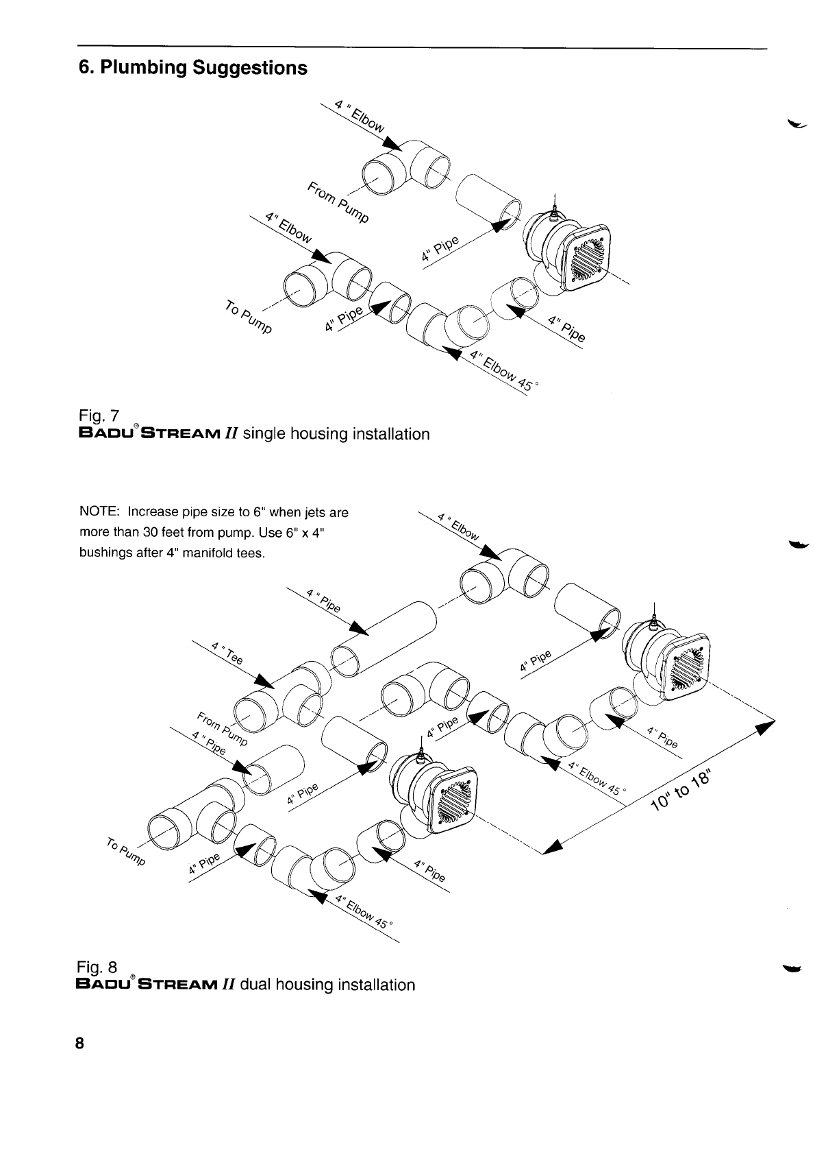
6.
Plumbing
Suggestions
Fig.7
Elaou-STFTEAM 11
singlehousing
installation
NOTE:
Increase
pipe
sizeto
6"
when
jets
are
morethan
30feetfrom
pump.
Use
6"x4"
bushings
aller
4"manifold
tees.
Fig.
B
EIADU"
SrRee,rvl 11
dualhousing
installation
8
\z-
-,
-

v
>
NOTE:Increase
pipe
sizeto6' when
jets
are
more
than30
feetfrom
pump.
Use6"x4"
bushings
after
4' manifoid
tees.
Fig.
9
Baou"SrFrEAM 11triplehousing
installation
NOTE:
Checkvalvesmust
beusedonthe
discharge
side
of
each
pump.
N4inimum4"
pipe
between
pump
andBaduStream
plumbing
manifold.
94^
-{Qk'"-{rqi'
7.Installation
ofthePump
andthe
ControlBox
lAcAUTloNl:
Beforeinstalling
the
SpeckPump,
read
theentire
pump
owner'smanual
found
in thepump
oox.
Consultlocal
codesfor minimum
distance
between
pump
and
pool.
Locate
pump
asclosetothe
pool
as
practical.
Theairbutton
works
upto 50 ft.Thereis50ft.of air
tubingin
BaouSrFrEAM 1/box.
trWARNtNGl:
Toreduce
therisk
ofinjury,
donot
permit
children
to use
this
product
unlessthey
areclosely
supervisedat
alltimes.
Thewiring
of the pool
motor
andcontrol
boxshould
bedoneby a licensed
electrician
inaccordancewith
localcodes.
Be certain
thatthe motorframe
and
control
box are grounded.
Motorname platehas
voltage, phase, amp draw, and other motor
information
as
well
aswiring
connection
instructions.
BONDING:
As required
by NationalElectrical
Code
Article
680-22,the pump motormustbe electrically
bondedtothepool
structure
(reinforced
bars,etc.)
by
a solid
copperconductornot
smallerthanNo.
8 AWG
via the external
copperbondinglug on the pump
moIor.
GROUNDING:Permanently
ground
thepump
motor
andcontrol
boxusing
a conductorofappropriate
size.
Connectto the No.10 green
headed
ground
screw
provided
inside
themotor
terminal
box.
NOTE:
Do notconnectto electric
power
supply
until
unitis
permanently
grounded.
Section
6 concernsthe
electricmotor
andcontrolbox
onlysince
allother
parts,
the
pump,
the
jetunit,etc.
have
complete
andabsolute
separationfromthepool
water.
I

8.Operation
lnstructions
Remove
redfiller
plug
or strainer
tank
lidon pump
andfill
pump
with
water.
Replace
red
filler
ptug
orlid.
Push
pneumatic
button
on.For
thefirst
start-up
allow
approximately
5 minutes
forthepump
to prime.
lfthe
pump has not stafted
priming
after5 minutes,
the
amount
of water
inthepump
was not
sufficient.
Add
more
water.
To start
swimming,
jogging
or running
itissuggested
that
the two nozzles
are pointed
slighfly
inward
and
slightly upward so that the water "breaks"
approximately
3ft.in front
of the Baousrneavr 11
Startswimming
with
onlyminimal
force
in armsand
legsuntil
you feel yourself
drifting
backwards,
then
addforce
andswim
upstream
until
a proper
balance
isfound
betweenforce
andendurance.
Keep
in
mind
thatthis
unitis
designed
for
a balanced
workout.
Find
a pace
that
you
cankeep
upfor
atleast
20 minutes.
Out
pacing
isalways
possible.
Theidea
is
tocontinue
exercisefor
anextended
period
of
time.
Consult your physician before attemptingany
strenuous exercise.This product may not be
challenging
or satistying
for all levels
of exercise.
The air regulator
permits
a controlled
mixture
of air
intothe
water
flow
and
creates
a unique,
invigorating,
bubble bath effect. lt wili also add additional
resistance
toswim
against.
Et^aousiTRearu
11's
adjustableflownozzle
enables
swimmerto regulate
the volume
of water released
through
the jet(s).
Turning
the nozzle
clockwise
reduces
theflow.
The swivelnozzle(s)
of the EtaclusiTFlea,u 11
can
be positioned in various directions,allowing
swimmerstousevarious
swim
styles.
OPTION:A pulsating
massage
hose
canbeattached
to oneofthenozzlesformassages.
(Askyour
dealer
for availability.)
Use massage
hose as advised
by
yourphysician.
Directions
for use: Consult
your physician
before
usingthemassage
hose.
To reduce
therisk
ofinjury,
do notpermit
children
to use
themassage
hosewith
pulsator
unless
they are closely
supervised
at all
times.
Close
air regulator.
Reduce
the volume
of
water by turning the adjustable
flow nozzle(s)
clockwise.
Undercertain
conditions
itispossible
that
thecurrent
"drifts
off"the
theleft
ortheright
fromthemiddle
due
towater
bouncing
off
the
backwall.
Inthe
eventthatit
interferes
with
your
swimming
action,
turnunit
off
for
afew
minutes
andrestart.
EWAiNlltclDo
notuseoroperatetheE4ousrneau 1I
if
thesquare,
anti-entrapment
coverismissing,
broken,
or loose.
v
v
9.Winterizing
In areassubject
to freezing
water
temperatures,
protect
pump
byremoving
drain
plug
andred
filler
ptug
(or
lid). Drain
pool
untilwater
levelhas
dropped
belowthesquare,
anti-entrapment
cover.Alternatively
purchase
a winter
coverkit
part
#2308752006K.
10.
Frequently
Asked
Questions
Whatsize pool do I need?Thes^aousTREAM 11
can be installed
in any size pool. However,
we
recommend
a minimum
length
of 14'and
a minimum
width
ofaswimming
lane.
What
size
plumbing
is
necessary?
How
far
awayfrom
theBaousrnea,vlllcan the
pump
beinstalled?
Use
a4"
plumbing
upto
30'.
For
runs
longer
than
30'
use6"
plumbing.
The pump can be placed
as closeto
EtADUsTFrel.w-
II aslocal
codeswill
allow.
Howmany
ampsdoes
the pumpoperate
at?
4 HP:
Maximum
19.4
amps
@230V
3.5HP:
Maximum
13.6
amps
@230V
What size breaker
do I need?You mustusea 40
amp
breaker
forthe
4 HP
pump
or30amp
breaker
for
the
3 HP
pump
toavoidnuisance
tripping.
10
Does
it matter
ifthehousing
is installed
higher
or
lower than the manual states? Yes,
the center
of
the
jet
must
be10 BELOW
estimated
waterlevel
for
properperformance
ofunit.
Can the air regulator be placedelsewhere?
Yes,
as
long
asitisnot
continuouslyflooded
withwater.
Canthe pump be placed belowwater level?
Yes.
However,
for best performance
we recommend
ordering
pump
forflooded
suction
(Model
21-80i33G)
instead
of self-priming(Model
21-80133
GS). We
recommend
installing
valves
for
ease
ofmaintenance.
How far away can the air button function
properly?A maximum
of 5O'.
Consultfactory
for
distances
over
50'.
Do I need to install a motor starter? No the pump
has
a built-inthermaloverload.

\t
-
11.Partslistfor EIAclU'STFTEAnvl.II
f,
f
V
---E
Y
18
IJ
to
6
v
\t
Part# Qty
'II
26
JI
f,l
ol
71
B1
911 4
912 B
9/3 8
914 8
9/5 4
'10 1
11/1 1
11t2 2
tz I
13 1
(14-21) 1
vt+1
15 1
162
Description
FaceRing
-Nozzle
Screw
-
Tapping
5.5x 19
ClampingRing
Nozzle
(adjustable
flow)
Bushing
Hose
Connector1/4"
Housing
SquareCover
Bolt-M6x25
Bolt-M6x20
Bolt-M6x25
Bolt-M6x40
Bolt-M6x45
Seat
-Nozzle
SpacerRing
-
6.2
Spacer
Ring
-
4
Gasket
-
ClampingRing
Gasket
-Face
Ring
HolderW/hose
Subassembly
Hose
Fitting
- 1/4"
Hose-8x3
Hose
Clamp14l9
Part# Qty
17 1
18 2
192
202
21 1
(22-26) 1
zal
zJl
24 1
25 1
26 1
272
'1
9t1
Optional
WinterCover Kit:
Part# Qty Description
1
12 1
9/1 4
- Extensionring
Description
Holder
-AirRegulator
BolI
- 1/4-20x 1-1
12"
Nut
- 1/4-20
Washer
- 1/4"
Gasket
60
x11x2
SubassemblyComplete
TopPart
-AirRegulator
Bottom
Part
-AirRegulator
Bolt
-Air
RegulatorM10xB0
Hose
Ring
-AirRegulator16x30
x80
Gasket
-Air
Control
42x 11
x2
Screw
-
Jet
Housing14x 1"
ExtensionRing
(pre-glued)(not
shown)
WinterPlate
(not
shown)
Gasket
-ClampingRing
Bolt-M6x25
An
extension
ring
(not
shown)isavailable
(upon
request)
11
12.
Limited
Warranty
Themanufacturer
supplies
a limited
warranty
to the
original
consumer
purchaser
ofthe
gaousrnearvl 11
onthefollowing
terms
andconditions:
1.
TheEtAclusTFlea,rvl
11iswarranted
tobefreefrom
defectsin material
andworkmanship
for a period
of
twelve (12) months from the date that the
EtAousTRea,ru
11is
originallyinstalled.
2.Notwithstanding
any
provision
herein
to
thecontrary,
thewarranties
andobligations
hereunder
shallnotin
any event
extend
for more
than2 years
beyondthe
date of shipment of the EtAclusTFtea,vr 11 from
Speck Pumps-Pool
Products,
Inc. in Jacksonville,
Florida.
3. Warranty
is voidin the following
cases:
damages
which
result
in whole
or in parl
from:
(a)careless
or
improper
installation
of the EtAclusTFr=arvr
II; (b)
improper
or negligent
use and maintenance
of the
BacIUSITFTEAM II; (c) tampering with the
EtaousiTFrea,rvl
11
byunauthorized
repair
personnel;
(d)ground
movement;(e)
substitution
of parts
and/or
components.
4.The
manufacturer's
sole
obligationhereunder
shall
be
toreplace
orrepair
any
defectiveEtAousTneana ^1L
The manufacturer
reserves
the absolute
rightto
determine
whether
anydefective
EIAclUsTne^aru
11
should
bereplaced
or
repaired.
5. Anycustomer
whowishes
to make
a claimunder
this Limited
Warranty
shallnotify
SpeckPumps,
of
such claim by telephone
or by mail. After the
customer
has beenauthorizedto return
a defective
BAousTneevr II, the customermust return
the
EtADUsTRea,rvl
11toSpeckPumps.
Any goods
returned
to Speck
Pumps
without
prior
authorization
will
be
returned
tothe
shipper
unopened.
Speck Pumpsshall not bear any costs or risks
incurred
inshipping
a defective
BAousTFrearvr Id
toSpeckPumps
orin
shippinga repaired
orreplaced
BArlusTne.aru 11toacustomer.
6. SpeckPumps
will
charge
customersfor all non
warranty
work
whichit mayperform.
Warranty
work
will not be performed
until the customerhas
acceptedthe
pricequoted.
7.Except
as specifically
setforth above,no other
warranties,
whether
express
or implied,including
without limitation, the implied warranties of
merchantability and fitness for a particular
purpose, are made by the manufacturer.
In no
eventwill the manufacturer
beliablefor any loss,
includingtime, money,goodwill, lost profits and
consequentialdamages based on contrast, tort
or other legal
theory,
which mayarise hereunder
or from the use,operationor modification
of the
pump, motor or associated
parts.The maximum
liability of the manufacturer
hereunder
shall not
exceedthe amountactually
paidby the customer
for the Fump,
motorandassociated
parts.
8.Somestates
donot
permit
limitations
onthe
terms
of implied
warranties
orontherecovery
of incidental
or consequentialdamages. Accordingly, the
limitations
contained
in paragraph
7, maynotapply
tocertain
customers.
9.Thiswarrantygives
customers
specificlegal
rights
which may vary from state to state. The
EIAEUsTFrea,ru
11is manufactured
underlicense
from
Speck
Pumpen,
GERMANY.
v.
v
Date
ofInstallation:
Installed
By:
For
Service
Call:
SAVETHESE
INSTRUCTIONS!
5PSI(_tr
PUmPScffi
q)
J
0.)
F
frl
F
a
ct)
F
o
v
U
fTl
(n
LH-F
i.l c E^
6--X
&d6d6=
q)
q)
-/A
Aotrdd
.IdHH
H EIeq
rvvv
'a (nQd/
X
a
+F
o ----___1}'
N
l.
-T-
I
I
I
I
I
3
I
Y
q)
\)>
\v
H
C)
!
C)
d
@aa)
0N!!E
AFFFg
a
: r/)F-o\ ^
ll19
F ca ..,f- .b
v9
E TfF:
5 6EEE
U >>>
E
Hx 9996
IHH>
;i ''f i'-'i /a
HHHV
a
+
X
\
\
\
\
\
\
\<\
\
\
\
\
rFl
z
^
O
\
\
\
\
i1
\
\
\
Table of contents
Other Speck Lighting Equipment manuals

Popular Lighting Equipment manuals by other brands


TECHTOP
TECHTOP URANUS 18 WW 25 user manual

National Specialty Lighting
National Specialty Lighting LED Brick Star Gen I installation instructions

JARDINICO
JARDINICO LUNA LED LIGHT Assembly and operation guide

LED World
LED World FA36M57-2M-12V-X Important instructions

GE
GE Arize Element Series installation guide

BeLuce
BeLuce MAXIMA TSL instructions