manuals.online logo
Brands
  1. Home
  2. •
  3. Brands
  4. •
  5. DTS
  6. •
  7. Lighting Equipment
  8. •
  9. DTS Discharge Lamp 35-70-150W User manual

DTS Discharge Lamp 35-70-150W User manual

GB
Made in Italy
User’s Manual Rel 1.1
D.T.S. Illuminazione srl - ITALY
http://www.dts-lighting.it
PROFILO COMPACT
Z 20° - 40°
PROFILO COMPACT
Z 20° - 40°
Discharge Lamp 35-70-150W
2
Le informazioni contenute in questo documento sono state attentamente redatte e
controllate. Tuttavia non è assunta alcuna responsabilità per eventuali inesattezze. Tutti
i diritti sono riservati e questo documento non può essere copiato, fotocopiato,
riprodotto per intero o in parte senza previo consenso scritto della DTS .
DTS si riserva il diritto di apportare senza preavviso cambiamenti e modifiche estetiche ,
funzionali o di design a ciascun proprio prodotto. DTS non assume alcuna responsabilità
sull'uso o sull'applicazione dei prodotti o dei circuiti descritti.
The information contained in this publication has been carefully prepared and checked.
However, no responsibility will be taken for any errors. All rights are reserved and this
document cannot be copied, photocopied or reproduced, in part or completely, without
prior written consent from DTS.DTS reserves the right to make any aesthetic, functional
or design modifications to any of its products without prior notice. DTS assumes no
responsibility for the use or application of the products or circuits described herein.
Les informations contenues dans le présent manuel ont été rédigées et contrôlées avec
le plus grand soin. Nous déclinons toutefois toute responsabilité en cas d'éventuelles
inexactitudes. Tous droits réservés. Ce document ne peut être copié, photocopié ou
reproduit, dans sa totalité ou partiellement, sans le consentement préalable de DTS.
DTS se réserve le droit d'apporter toutes modifications et améliorations esthétiques,
fonctionnelles ou de design, sans préavis, à chacun de ses produits. DTS décline toute
responsabilité sur l'utilisation ou sur l'application des produits ou des circuits décrits.
Las informaciones contenidas en este documento han sido cuidadosamenteredactadas y
controladas. Con todo, no se asume ninguna responsabilidad por eventuales
inexactitudes. Todos los derechos han sido reservados y este documento no puede ser
copiado, fotocopiado o reproducido, total o parcialmente, sin previa autorizaciónescrita
de DTS.DTS se reserva el derecho a aportar sin previo aviso cambios y modificaciones
de carácter estético, funcional o de diseño a cada producto suyo. DTS no se asume
responsabilidad de ningún tipo sobre la utilización o sobre la aplicació
n de los productos o de los circuitos descritos.
PROFILO COMPACT
MADE IN ITALY
3
INDEX
Technical features pag 4
Important Safety informations pag 6
Mounting the lamp pag 7
Voltage and frequency pag 8
Installation pag 8
Mains connection pag 8
Projector use pag 9
Opening the projector housing pag 10
Periodic cleaning pag 11
Periodic controls pag 11
PROFILO COMPACT
4 PROFILO COMPACT
1 TECHNICAL FEATURES
PROFILO COMPACT is a new range of small and lightweight shapers, ideal for use in theatres,
showrooms, shops, museums, churches, trade fairs, conferences, etc.
PROFILO COMPACT models offer an elegant and compact design and a choice of different
finishes for easy installation even in the most refined settings.
PROFILO COMPACT has an internal system with four shutters to give high-precision shaping of
light beams.
PROFILO COMPACT also offers a series of high-level operating features neatly fitted into an
extremely small space.
PROFILO COMPACT is available in 2 versions: with halogen lamp (max 300W), or discharge lamp
(150W / 70W / 35W) with built-in ballast.
PROFILO COMPACT 35W (Cod. 03.TP006)
35W discharge lamp • Black colour
PROFILO COMPACT 70W (Cod. 03.TP004)
70W discharge lamp • Black colour
PROFILO COMPACT 150W (Cod. 03.TP003)
150W discharge lamp • Black colour
PROFILO COMPACT HALO 300W (Cod. 03.TS004.F)
300W halogen lamp • Black colour
Construction
Extremely compact and lightweight
Steel housing with aluminium edge profiles
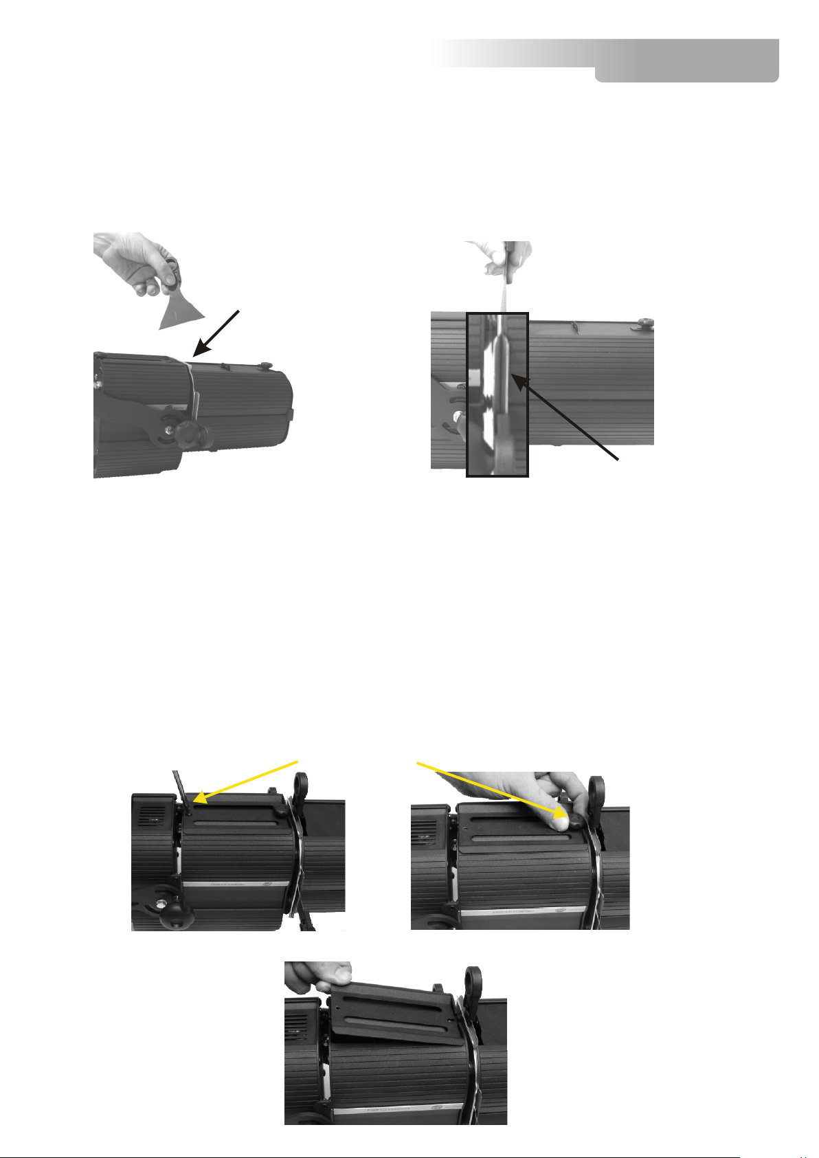
Front-box for filter frame and barn door with locking system
Gobo holder for image projection (optional)
Internal ventilation labyrinth
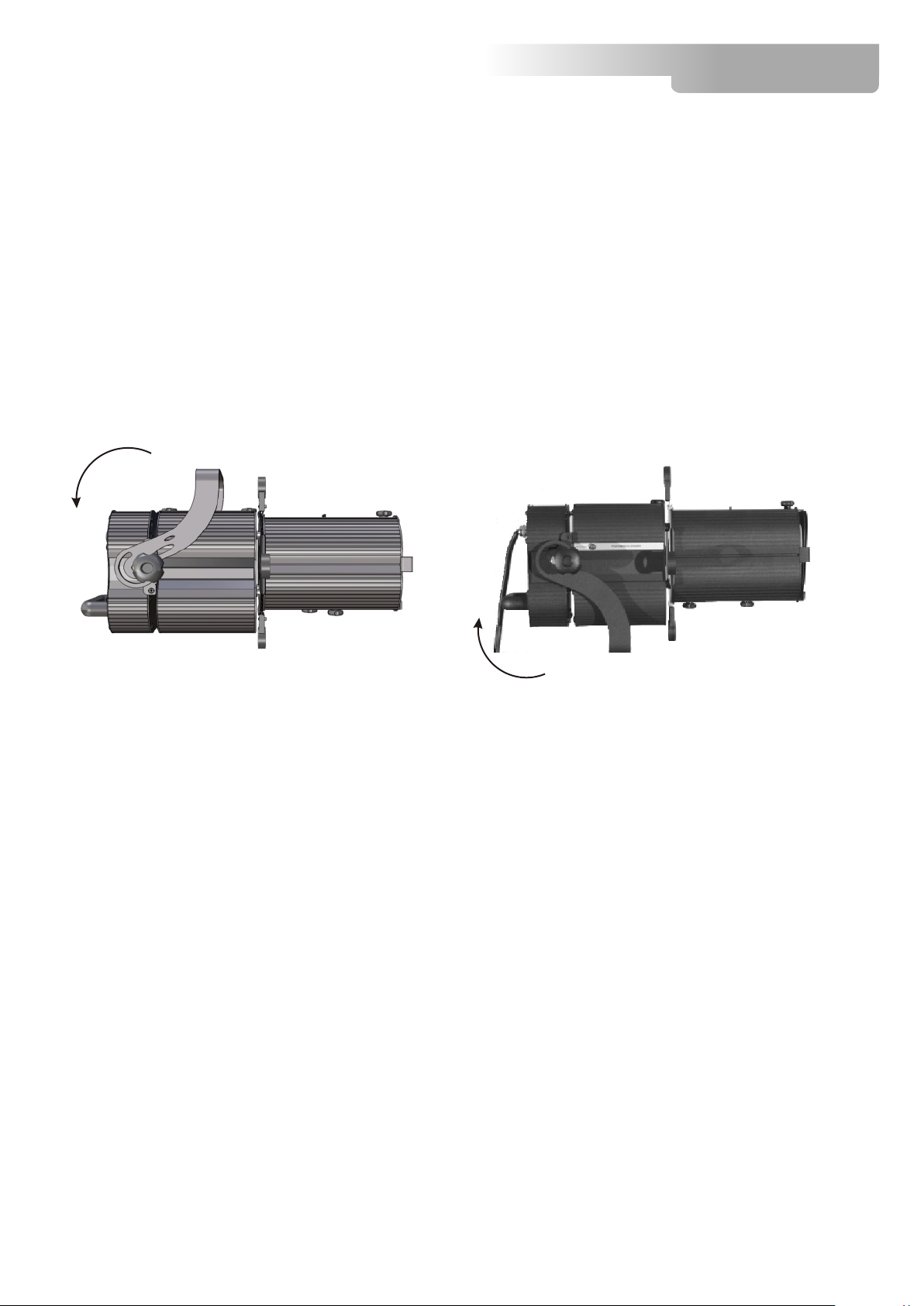
Removable cover for easy access to lamp
Reversible yoke for using the projector in any position
Finishings
Black, White (RAL 9003), Grey (RAL 9006) or other colours on demand
Safety
Frontal protection grille (removable)
Heat insulated knobs and handles
Optical unit
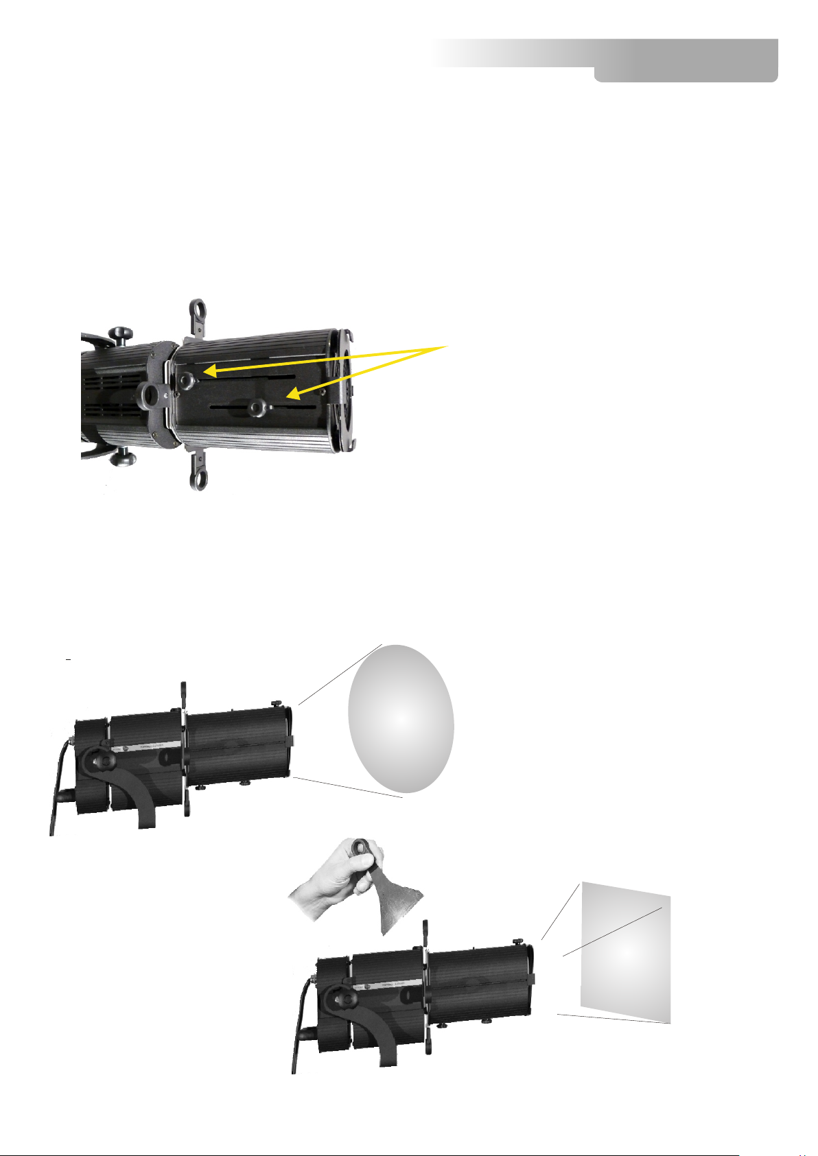
High definition zoom lens with double optical condenser lens
Optical tempered glass lenses with anti-reflective coating
Focal adjustment from 20° to 40°, giving precision movement on a double track
Spherical reflector in polished and treated 99.9% aluminium
Internal system with four removable shutters
Iris
Iris diaphragm
Lampholders
G12 lampholder for discharge lamps (150W / 70W / 35W)
GY9,5 lampholder for halogen lamps (max 300W)
Power supply
230V 50/60Hz
Built-in ballast 230V 50/60Hz (discharge lamp models)
PROFILO COMPACT
1 TECHNICAL FEATURES
ACCESSORIES
• Barn-door, black finishing (Cod. 03.TA206)
• Iris/diaphragm for Profilo Compact (Cod. 03.TA207)
• Gobo holder (Cod. 03.TA208)
• “C” Clamp G30 black (max. load 5Kg) (cod. 0521A020)
• “C” Clamp G30 chrome (max. load. 5Kg) (cod. 0521A020.20)
• Safety wire (3mm x 60 cm), ring spring catch (max. load 60Kg) (cod. 0521A010)
• GY9,5 M38 300W 230V halogen lamp (Cod. 0505A032)
• GY9,5 CP81 300W 230V halogen lamp (Cod. 0505A005)
• CDM-T150/832 (MCD 150W) discharge lamp (Cod. 0505S003.1)
• CDM-SA/T 150/942 discharge lamp (Cod. 0505S003)
• HSD 150W discharge lamp (Cod. 0505S003.2)
• Gel filters
PROFILO COMPACT
DISCHARGE LAMP 150W
mm 173
mm 154
mm 429
mm 388
mm 143
5
6 PROFILO COMPACT
2 IMPORTANT SAFETY INFORMATION
2.1 Fire prevention
-Never locate the fixture on any flammable surface.
-Minimum distance from flammable materials: 10 CM.
-Minimum distance from the closest illuminable surface: 30 CM.
-Connect the projector to mains power via a thermal magnetic circuit breaker.
2.2 Prevention of electric shock
-High voltage is present inside the unit. Unplug the unit prior to performing any function
which involves touching the inside, including lamp replacement.
-A good earth connection is essential for proper functioning of the projector.
-Never connect the unit without proper earth connection.
-The fixture should be located in places with a good air ventilation.
2.3 Protection against ultraviolet radiation
-Never turn on the lamp if the front lenses are damaged. Their respective shielding
function will only operate efficiently if they are in perfect working order.
-Never look directly the lamp when it is on.
2.4 Safety
-The projector should always be installed with bolts, clamps and other tools that are
capable of supporting the weight of the unit.
-Always use a second safety cable to sustain the weight of the unit in case of the failure
of the main fixing point.
-The external surface of the unit, at various points, may exceed 70°C. Never handle the
unit until at least 10 minutes have elapsed since the lamp was turned off.
-Always replace the lamp if any physical damage is evident.
-Never install the fixture in an enclosed area lacking sufficient air flow. The ambient
temperature should not exceed 40°C.
-A hot lamp may explode, so always wait for at least 10 minutes prior to attempting to
replace the lamp.
-Always wear suitable hand protection when handling the lamp.
2.5 Level of protection against the penetration of solid and liquid objects
-The projector is classified as an ordinary appliance and its protection level against the
penetration of solid and liquid objects is IP 20.
The projector contains electric and electronic components which should under no
circumstances come into contact with oil, water or any other liquid. The proper unit
functioning would be compromised should this occur.
7 PROFILO COMPACT
3 MOUNTING THE LAMP
1) Loose the screw and the knob located on the top back side of the unit
(Photo 1 and 2).
2) Remove the top back cover (photo 3) and insert the lamp (photo 4).
No lamp allignment needed
The lamp used is manufactured from quartz glass and should be handled with care.
Always adhere to the instructions supplied in the lamp's packaging. Never touch the
glass directly but use the tissue provided in the lamp's packaging. The G12 lampbase is
symmetrical.
DO NOT USE UNDUE FORCE ON THE GLASS. In case of difficulty, re-read the
instructions and repeat the procedure.
Photo 1 Photo 2
screw and knob
Photo 3 Photo 4
PROFILO COMPACT
4 VOLTAGE AND FREQUENCY
Profilo Compact with discharge lamp operates at 230V 50 - 60 Hz.
5 INSTALLATION
Profilo Compact may be either floor or ceiling mounted.
For ceiling mounted installations, we reccomend the use of appropriate clamps to fix
the unit to the mounting surface.
A safety cable must always be present.
6 MAINS CONNECTION
PROFILO COMPACT with discharge lamp operates at 230 VOLT 50-60 Hz.
Prior to connecting the unit to your mains supply, ensure that the model in your
possession correctly matches the mains supply available. For connection purposes,
ensure that your plug is capable of supporting 1,5 amps at 230V,
6.1 Protection
The use of a thermal magnetic circuit breaker is recommended for each unit.
A good earth connection is essential for the correct operation of the projector.
ceiling installations Floor installations
WARNING: The rear side of the unit, can reach very high temperature.
Handle the projector with extreme caution
8
7 PROJECTOR USE
7.1 Focus and Zoom
.
7.2 Blades
Profilo Compact is provided with four indipendent steel blades.The blades let you
create geometrical figures with the light.
Focus and zoom adjustment lenses, are located on the front side of the unit.
Place the projector on the object to illuminate, loose the fixing lenses , adjust the
lenses position till the projection is whell focused on the object.
Thighten the knobs
knobs
PROFILO COMPACT
Focus and Zoom
Light beam with no blades inserted
Blade
Light beam with blades inserted
9
PROFILO COMPACT
7.3 Blades insertion
To insert the blades on the unit, proceed as follow:
Locate the blades holder, place one side of the blade within the two parallel surfaces,
push and tilt it on the guide.
Warning:
8 OPENING THE PROJECTOR HOUSING
8.1 Back side
It is possible to inspect the inside of the projector by removing the cover as indicated below.
Remove mains power prior to accessing the projector’s internal
components.
1) Loose the screw and the knob located on the top back side of the unit (photo 1 and 2).
2) Remove the top back side cover (photo 3)
Blades holder
7.3 Blades insertion
To insert the blades on the unit, proceed as follow:
Locate the blades holder, place one side of the blade within the two parallel surfaces,
push and tilt it on the guide.
Warning:
8 OPENING THE PROJECTOR HOUSING
8.1 Back side
It is possible to inspect the inside of the projector by removing the cover as indicated below.
Remove mains power prior to accessing the projector’s internal
components.
1) Loose the screw and the knob located on the top back side of the unit (photo 1 and 2).
2) Remove the top back side cover (photo 3)
Parallel surfaces
screw and knob
Photo 1 Photo 2
Photo 3
10
11 PROFILO COMPACT
8.2 Front side (Focus - Zoom lenses)
1) Loose the knob located on the top front side of the unit (photo 1)
2)
9 PERIODIC CLEANING
Lenses and reflectors
Even a fine layer of dust can reduce the luminous output substantially. Regularly clean
all lenses and the reflector using a soft cotton cloth, dampened with a specialist lens
cleaning solution.
10 PERIODIC CONTROLS
Lamp
The lamp should be replaced if there is any visible damage or deformation due to heat.
This will help to avoid the danger of the lamp explosion.
Mechanical parts
Periodically check all mechanical parts, replacing them if necessary.
Warning:
Disconnect mains power prior to removing the projector housing.
Now it is possible to move the covers for internal inspection (photo 2)
Photo 1
Photo 2
The information contained in this publication has been carefully prepared and checked.
However, no responsibility will be taken for any errors. All rights are reserved and this document
cannot be copied, photocopied or reproduced, in part or completely, without prior written consent
from D.T.S.
D.T.S. reserves the right to make any aesthetic, functional or design modifications to any of its
products without prior notice. D.T.S. assumes no responsibility for the use or application of the
products or circuits described herein.
MADE IN ITALY
D.T.S. Illuminazione s.r.l - Via Fagnano Selve 10-12-14 47843 - Misano Adriatico (RN) Italy
Tel. +39 0541 611131 Fax +39 0541 611111 [email protected] www.dts-lighting.it
*0517i078*
*0517I078*

Other DTS Lighting Equipment manuals

DTS Thomas & Betts NT 06 Manual

DTS

DTS Thomas & Betts NT 06 Manual

DTS XR5 SPOT User manual

DTS

DTS XR5 SPOT User manual

DTS DELTA R FULL COLOR User manual

DTS

DTS DELTA R FULL COLOR User manual

DTS NICK NRG1200 CT User manual

DTS

DTS NICK NRG1200 CT User manual

DTS Scena LED 150 User manual

DTS

DTS Scena LED 150 User manual

DTS DIVE/R 18 RGB User manual

DTS

DTS DIVE/R 18 RGB User manual

DTS SCENA COMPACT LED 50 User manual

DTS

DTS SCENA COMPACT LED 50 User manual

DTS 03.P16.02.01.LED PAR16 LED MR16 BLACK User manual

DTS

DTS 03.P16.02.01.LED PAR16 LED MR16 BLACK User manual

DTS XR 8 Wash User manual

DTS

DTS XR 8 Wash User manual

DTS ALCHEMY 5 User manual

DTS

DTS ALCHEMY 5 User manual

DTS PAR64Ip66 watertight User manual

DTS

DTS PAR64Ip66 watertight User manual

DTS FOS 100 FULL RGBW User manual

DTS

DTS FOS 100 FULL RGBW User manual

DTS MOON 1200 User manual

DTS

DTS MOON 1200 User manual

DTS Z8 User manual

DTS

DTS Z8 User manual

DTS JACK User manual

DTS

DTS JACK User manual

DTS PROFILO 500 User manual

DTS

DTS PROFILO 500 User manual

DTS TITAN SOLO User manual

DTS

DTS TITAN SOLO User manual

DTS FOS 100 WHITE 36 User manual

DTS

DTS FOS 100 WHITE 36 User manual

DTS SCENA COMPACT LED 50 User manual

DTS

DTS SCENA COMPACT LED 50 User manual

DTS XR1200 WASH Fresnel User manual

DTS

DTS XR1200 WASH Fresnel User manual

DTS XR2000 BEAM User manual

DTS

DTS XR2000 BEAM User manual

DTS PROFILO LED 80 User manual

DTS

DTS PROFILO LED 80 User manual

DTS NICK NRG 1201 User manual

DTS

DTS NICK NRG 1201 User manual

DTS A.R.C. User manual

DTS

DTS A.R.C. User manual

Popular Lighting Equipment manuals by other brands

Starling Technologies Pocket Spin Drift instruction manual

Starling Technologies

Starling Technologies Pocket Spin Drift instruction manual

Robe Color mix 575 AT user manual

Robe

Robe Color mix 575 AT user manual

dehn HVI Series installation instructions

dehn

dehn HVI Series installation instructions

Uwatec Nova 700R Guide

Uwatec

Uwatec Nova 700R Guide

HP 5501B Operating and service manual

HP

HP 5501B Operating and service manual

ETI Solid State Lighting 504071020 Use and care guide

ETI Solid State Lighting

ETI Solid State Lighting 504071020 Use and care guide

DOTLUX 2840-1 user manual

DOTLUX

DOTLUX 2840-1 user manual

LIGMAN ODESSA 22 installation manual

LIGMAN

LIGMAN ODESSA 22 installation manual

dymax BlueWave MX-150 user guide

dymax

dymax BlueWave MX-150 user guide

ML Accessories TRLED14EM Installation & maintenance manual

ML Accessories

ML Accessories TRLED14EM Installation & maintenance manual

Aurora T8 instructions

Aurora

Aurora T8 instructions

LIGMAN KWH 8 installation manual

LIGMAN

LIGMAN KWH 8 installation manual

Commercial Electric GRD150-PC-4K-BZ Use and care guide

Commercial Electric

Commercial Electric GRD150-PC-4K-BZ Use and care guide

Conrad 56 21 80 operating instructions

Conrad

Conrad 56 21 80 operating instructions

Ayrton ZONDA 9 WASH user manual

Ayrton

Ayrton ZONDA 9 WASH user manual

COLBOR BP45 user manual

COLBOR

COLBOR BP45 user manual

Chauvet ColorAdo 1-Quad IP user manual

Chauvet

Chauvet ColorAdo 1-Quad IP user manual

EuroLite LED Bow Bar 288/4 MCL user manual

EuroLite

EuroLite LED Bow Bar 288/4 MCL user manual

manuals.online logo
manuals.online logoBrands
  • About & Mission
  • Contact us
  • Privacy Policy
  • Terms and Conditions

Copyright 2025 Manuals.Online. All Rights Reserved.