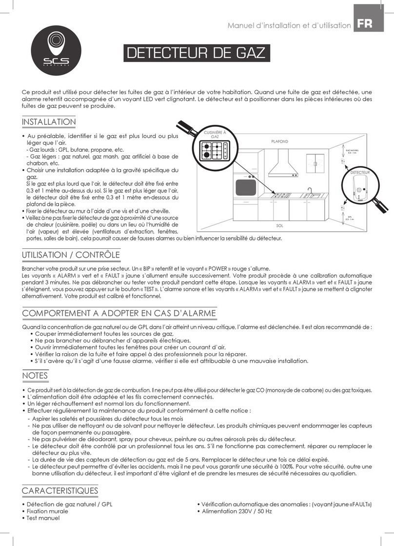
Spectrex SafEye Quasar 900 User manual

Manual
TM888200, Rev Ar
May2023
SafEye™ Quasar 900
Open Path Combustible Gas Detectors

Legal notice
The device described in this document is the property of Emerson.
No part of the hardware, software, or documentation may be reproduced, transmitted, transcribed, stored in a
retrieval system, or translated into any language or computer language, in any form or by any means, without prior
written permission of Emerson.
While great efforts have been made to ensure the accuracy and clarity of this document, Emerson assumes no liability
resulting from any omissions in this document or from misuse of the information obtained herein. The information in
this document has been carefully checked and is believed to be entirely reliable with all of the necessary information
included. Emerson reserves the right to make changes to any products described herein to improve reliability,
function, or design and reserves the right to revise this document and make changes from time to time in content
hereof with no obligation to notify any persons of revisions or changes. Emerson does not assume any liability arising
out of the application or any use of any product or circuit described herein; neither does it convey license under its
patent rights or the rights of others.
WARNING
Physical access
Unauthorized personnel may potentially cause significant damage to and/or misconfiguration of end users’
equipment. This could be intentional or unintentional and needs to be protected against.
Physical security is an important part of any security program and fundamental in protecting your system. Restrict
physical access by unauthorized personnel to protect end users’ assets. This is true for all systems used within the
facility.
2

Contents
Chapter 1 About this guide........................................................................................................................5
1.1 Release history.............................................................................................................................5
1.2 Glossary and abbreviations........................................................................................................6
1.3 Notifications................................................................................................................................. 7
Chapter 2 Product overview...................................................................................................................... 9
Chapter 3 Technical description..............................................................................................................11
3.1 Features......................................................................................................................................11
3.2 Applications................................................................................................................................11
3.3 Principles of operation..............................................................................................................12
3.4 Product certification..................................................................................................................14
3.5 Models and types...................................................................................................................... 16
3.6 Description................................................................................................................................. 16
Chapter 4 Operating modes.................................................................................................................... 19
4.1 Operational modes................................................................................................................... 19
4.2 Visual indicators........................................................................................................................ 20
4.3 Output signals........................................................................................................................... 20
4.4 System setup..............................................................................................................................21
Chapter 5 Technical specifications......................................................................................................... 25
5.1 General specifications...............................................................................................................25
5.2 Electrical specifications.............................................................................................................26
5.3 Electrical outputs.......................................................................................................................26
5.4 Mechanical specifications.........................................................................................................27
5.5 Environmental specifications...................................................................................................27
Chapter 6 Installation instructions........................................................................................................ 29
6.1 Introduction............................................................................................................................... 29
6.2 General considerations.............................................................................................................29
6.3 Preparations for installation.................................................................................................... 31
6.4 Certification instructions.......................................................................................................... 32
6.5 Conduit/cable installation........................................................................................................ 33
6.6 Receiver/transmitter mounting...............................................................................................34
6.7 Receiver wiring.......................................................................................................................... 34
6.8 Receiver terminal wiring...........................................................................................................37
6.9 Transmitter wiring.....................................................................................................................38
Chapter 7 Operating instructions........................................................................................................... 41
7.1 Safety operation........................................................................................................................ 41
7.2 Alignment of unit.......................................................................................................................41
7.3 Powering up the system...........................................................................................................42
7.4 Safety precautions.....................................................................................................................42
7.5 Signal verification...................................................................................................................... 43
7.6 Zero calibration..........................................................................................................................43
Manual Contents
TM888200 May2023
SafEye™ Quasar 900 3

7.7 Functional check........................................................................................................................44
Chapter 8 Maintenance instructions......................................................................................................45
8.1 General maintenance............................................................................................................... 45
8.2 Periodic maintenance............................................................................................................... 45
Chapter 9 Troubleshooting...................................................................................................................... 47
Chapter 10 Declaration of Conformity..................................................................................................... 49
Appendix A Wiring configurations.............................................................................................................51
Appendix B Accessories...............................................................................................................................53
B.1 Tilt mount...................................................................................................................................53
B.2 Pole mount (U-Bolt 4-5-in.).......................................................................................................53
B.3 Pole mount (U-Bolt 2-3-in.).......................................................................................................53
B.4 Wall mount.................................................................................................................................53
B.5 Commissioning kit.................................................................................................................... 53
B.6 HART handled diagnostic unit................................................................................................. 54
B.7 Universal RS-485 and HART IS harness kit.............................................................................54
B.8 USB/RS-485 harness converter kit.......................................................................................... 54
B.9 Protective cover.........................................................................................................................54
Appendix C SIL-2 features...........................................................................................................................55
C.1 Safety relevant parameters..................................................................................................... 55
C.2 General conditions for safe use.............................................................................................. 55
Contents Manual
May2023 TM888200
4 Spectrex.net

1 About this guide
This manual describes the Quasar 900 Open-Path Gas Detection System and its features
and provides instructions how to install, operate, and maintain the receiver.
Note
This user guide should be carefully read by all individuals who have or will have
responsibility for using, maintaining or servicing the product.
This guide includes the following chapters and appendices:
•About this guide - details the layout of the guide, includes the release history, a glossary
and abbreviations, and explains how notifications are used in the guide.
•Product overview - provides a general introduction and overview of the product and the
guide, with a brief description of its content.
•Technical description - describes the receiver’s theory of operation.
•Operating modes - describes the receiver’s operation modes, user interface and
indications.
•Technical specifications - describes the receiver’s electrical, mechanical and
environmental specifications.
•Installation instructions - describes how to install the receiver, including wiring and
mode settings.
•Operating instructions - describes the operating instructions and power-up procedures.
•Maintenance instructions - describes the maintenance and support procedures.
•Troubleshooting - describes the solutions to problems that may arise with the receiver.
•Wiring configurations - provides wiring diagrams for installation.
•Accessories - provides a list of accessories available for the Quasar 900 Open-Path Gas
Detection System.
•SIL-2 features - details the special conditions for compliance with the requirements of
EN 61508 for SIL-2.
1.1 Release history
Revision Date Revision history Prepared by Approved by
6 February 2013 First release Ian Buchanan Eric Zinn
7 June 2013 Second release Ian Buchanan Eric Zinn
8 August 2013 Third release Ian Buchanan Eric Zinn
9 January 2014 Fourth release Ian Buchanan Eric Zinn
10 August 2014 Fifth release Ian Buchanan Eric Zinn
11 January 2015 Sixth release Ian Buchanan Eric Zinn
12 January 2017 Seventh release Jay Cooley Ian Buchanan
13 February 2017 Eighth release Jay Cooley Ian Buchanan
Am March 2018 Ninth release Michal Heller Udi Tzuri
An February 2020 Tenth release Michal Heller Udi Tzuri
Manual About this guide
TM888200 May2023
SafEye™ Quasar 900 5

Revision Date Revision history Prepared by Approved by
Ao February 2021 Eleventh Release Michal Heller Udi Tzuri
Ap October 2021 Twelfth Release Michal Heller Udi Tzuri
Ar January 2023 Thirteenth release Yisrael Ivri Emil Cohen
1.2 Glossary and abbreviations
Abbreviation/term Meaning
Analog video Video values are represented by a scaled signal
ATEX Atmosphere Explosives
AWG American Wire Gauge
BIT Built-In-Test
CMOS Complementary Metal-Oxide Semiconductor image sensor
Digital video Each component is represented by a number representing a discrete
quantization
DSP Digital Signal Processing
EMC Electromagnetic Compatibility
EMI Electromagnetic Interference
EOL End of Line
FOV Field of View
HART Highway Addressable Remote Transducer – communications protocol
IAD Immune at Any Distance
IECEx International Electro-Technical Commission Explosion
IP Internet Protocol
IPA Isopropyl Alcohol
IR Infrared
JP5 Jet Fuel
LED Light Emitting Diode
MODBUS Serial communications protocol using Master-Slave messaging
N/A Not Applicable
N.C. Normally Closed
NFPA National Fire Protection Association
N.O. Normally Open
NPT National Pipe Thread
PAL Phase Alternation by Line (a color encoding system)
P/N Part Number
RFI Radio Frequency Interference
RTSP Real Time Streaming Protocol
SIL Safety Integrity Level
About this guide Manual
May2023 TM888200
6 Spectrex.net

UNC Unified Coarse Thread
VAC Volts Alternating Current
1.3 Notifications
This section explains and exemplifies the usage of warnings, cautions, and notes
throughout this guide:
WARNING
This indicates a potentially hazardous situation that could result in serious injury and/or
major damage to the equipment.
CAUTION
This indicates a situation that could result in minor injury and/or damage to the
equipment.
Note
This provides supplementary information, emphasizes a point or procedure, or gives a tip
to facilitate operation.
Manual About this guide
TM888200 May2023
SafEye™ Quasar 900 7

About this guide Manual
May2023 TM888200
8 Spectrex.net

2 Product overview
The SafEye™ Quasar 900 IR Open-Path Gas Detector employs an advanced Xenon Flash
transmitter and integrated electronics package, both of which are encased in improved
stainless steel housings, which provide high quality and performance, fast response, and
line-of-sight gas monitoring. The SafEye™ Quasar 900 Detector is backed by a 3-year
warranty.
The Quasar 900 detects ambient combustible gases over a path length of up to 660 ft/200
m, even in harsh environments where dust, fog, rain, snow, or vibration can cause a high
reduction of signal. The SafEye™ Quasar 900 can maintain operation in up to 95% signal
obscuration and ±0.5 degree of misalignment.
The Quasar 900 is manufactured only from stainless steel, with a heated optical window
to improve performance in ice, snow, and condensation conditions. The programmable
functions are available through a RS-485 or HART® port used with host software supplied
by Spectrex, and a standard PC or IS handheld unit. The HART can be connected on the
0–20 mA line or through the IS port.
The Quasar transmitter and receiver unit enclosures are approved Exd flameproof with
an integral segregated rear and an Exe terminal compartment, which avoids exposure of
the sensors and electronics to the surrounding environment. The receiver also has a plug
interface for connection to a handheld PC or HART unit, which meets intrinsically safe
standards. Hence the combined approval:
Ex II 2(2) G D
Ex db eb ib [ib Gb] IIB+H2 T4 Gb
Ex tb [ib Gb] IIIC T135 °C Db
Ta=-55 °C to +65 °C
This manual provides a full description of the detector and its features. It includes
instructions on the installation, operation, and maintenance of the detector.
•For additional settings and trouble shooting use the software on the product web page.
WARNING
The transmitter and receiver are not field-repairable due to the meticulous alignment and
calibration of the sensors and the respective circuits. Do not attempt to modify or repair
the internal circuits or change their settings, as this will impair the system's performance
and void the Spectrex product warranty.
Manual Product overview
TM888200 May2023
SafEye™ Quasar 900 9

Product overview Manual
May2023 TM888200
10 Spectrex.net

3 Technical description
3.1 Features
•One person installation and low maintenance
•Factory calibrated
•Built-in self test continuously monitoring device health
•Accurate and reliable high-speed response in under two seconds
•RTC event recorder; record of the last 375 events
•Automatic gain control ensures accurate detection in challenging conditions with up to
95% signal obscuration
•Three-year warranty
•High false alarm immunity
•Heated optics for operation in challenging conditions
•Easy to use, field configurable via HART® or RS-485 Modbus®
•High reliability-MTBF-minimum 100,000 hours
3.2 Applications
The Quasar 900 system is an optical control fence for combustible gases as defined in
the product specification, providing perimeter monitoring and early detection in various
applications, such as:
•Petrochemical, pharmaceutical, and other chemical storage and production areas
•Flammable chemical storage sites, and hazardous waste disposal areas
•Refineries, oil platforms, pipelines, refueling stations, and fuel storage facilities
•Hazardous loading docks, transportation depots, and shipping warehouses
•Engine rooms
•Compressor and pumping stations
•Test cells
•LNG-LPG Systems
•Offshore Floating Production Storage and Offloading (FPSO), and fixed oil rigs
Manual Technical description
TM888200 May2023
SafEye™ Quasar 900 11

3.3 Principles of operation
The Quasar system detects gases through dual-spectral range monitoring, analyzing the
absorption of radiation caused by gases in the atmosphere, and comparing the ratio to
background atmospheric absorption.
3.3.1 Definitions of terms
The following list defines gas concentration measurement terms that are used in this
manual:
Table 3-1: Gas concentrations measurement terms
Term Description
LEL Lower Explosive Limit: The minimum concentration of a substance (gas/
vapor) in air mixture that can be ignited. This mixture is different for every
gas/vapor, measured in % of LEL.
LEL.m Integral of Concentration in LEL units (1 LEL = 100% LEL) and the operation
distance in meters (m).
3.3.2 Spectral fingerprint
Each hazardous material is detected at a specific wavelength selected according to its
specific spectral absorption or “fingerprint.” The detection process involves 2 separate
filters: one transmitting radiation that is absorbed by a particular gas, and one that is not
sensitive to it.
3.3.3 Optical path
The presence of hazardous airborne vapors, gases, or aerosols in a monitored area
is detected when the defined substance crosses/enters the optical path between the
radiation transmitter unit and the receiver.
Hazardous gases/vapors present in the atmosphere cause absorption of the radiation
pulse at specific wavelengths in the optical path between the radiating transmitter and the
receiver unit. This causes a change in the signal intensity received by the receiver, which is
translated into an output related to the receiver’s measuring scale.
The system analyzes the defined open path at the spectral bands specific to the materials
being monitored. The Automatic Gain Control (AGC) unit compensates for environmental
disturbances such as fog and rain, through a constant comparison with its dual spectral
beam.
3.3.4 Microprocessor based
The incoming signals are analyzed by the built-in microprocessor. A sophisticated
mathematical algorithm calculates the various functions of the detected signal thresholds.
Statistics, ratio algorithms, data communications, diagnostics, and other functions are
performed.
3.3.5 Gas sensitivity
The SafEye™ Quasar 900 Model uses wavelengths around the 2.3μ spectral band
to measure air flammability potential between the transmitter and receiver. At this
Technical description Manual
May2023 TM888200
12 Spectrex.net

wavelength, all hydrocarbon materials have an absorption peak. This enables the receiver
to achieve regular sensitivity of 0–5 LEL.m.
The Quasar 900 detects hydrocarbon gases including methane, ethylene, propane, ethane,
butane, and others.
3.3.6 Gas calibration
The Quasar 900 has 3 calibrations that can be changed by function setup:
•Gas 1 – 100% methane
•Gas 2 – 100% propane
•Gas 3 – 100% ethylene
The full scale of methane and propane is 5 LEL.m, while the full scale of ethylene is 8
LEL.m. Gas calibration is available to LEL values defined by NFPA 325 and IEC 60079-20.
Instruments certified to ATEX/IECEx, UKCA, EAC, and Inmetro are calibrated to LEL values
defined by the IEC standard, while configurations certified to FM/FMC are calibrated per
the NFPA norm.
The full scale of methane and propane is 5 LEL.m.
3.3.7 Transmitter
The Xenon Flash transmitter was originally introduced in the first SafEye™ development and
was designed to overcome false alarms, which were experienced by early generations of
the open path system. The new SafEye™ Quasar 900 employs the latest generation of flash
bulbs to provide even more power and an extended operation life.
3.3.8 Heated optics
SafEye™ Quasar includes heated optics for the transmitter and receiver. To improve
performance in conditions where there is ice, condensation, or snow, the heater increases
the temperature of the optical surface to 68 °F/ 20 °C above the ambient temperature while
operating at high power. The heated optics are configured to automatically operate when
the change in temperature requires heating (default).
•OFF – Heating is always OFF
•ON – LOW – Heating is always ON – Low power
•ON – HIGH – Heating is always ON – High power
•AUTO – LOW – Low power
•AUTO – HIGH – High power
See System setup.
If Auto is selected the user can define the start temperature measured inside the device
below which the window will be heated. If the selected start temperature is above the
selected value, the heater will stay off.
3.3.9 HART® protocol
The Quasar 900 uses the HART Protocol.
HART Communication is a bi-directional industrial field communication protocol used to
communicate between intelligent field instruments and host systems. HART is the global
Manual Technical description
TM888200 May2023
SafEye™ Quasar 900 13

standard for smart instrumentation, and the majority of smart field devices installed in
plants worldwide are HART-enabled.
HART technology is easy to use and very reliable.
Through the HART connection, the SafEye is able to perform:
•Receiver setup
•Receiver troubleshooting
•Receiver health and status
For additional settings and trouble shooting use the software on the product web page.
HART communication can be connected on the 0–20 mA line or through the IS connection,
with a standard handheld unit loaded with the host software and attached by a special
harness.
3.3.10 Modbus RS-485
For more advanced communications, the Quasar 900 has a RS-485 Modbus-compatible
output that provides data communication from a network (up to 247 detectors) to a
host computer or universal controller for central monitoring. This feature enables easy
maintenance, with local and remote diagnostic tools.
3.3.11 Tilt mount
The newly designed stainless steel tilt mount provides a smaller installation footprint
that can conform to limited space constraints, while the sturdy construction maintains
alignment even with constant vibration. The improved X and Y axis worm-gear adjustments
provide quick and easy alignment for installation and maintenance procedures.
3.4 Product certification
3.4.1 ATEX, IECEx
The Quasar 900 is ATEX approved per SIRA 12ATEX1212X and IECEx per IECEx SIR 12.0086X
per:
•Ex II 2(2)G D
Ex db eb ib [ib Gb] IIB+H2 T4 Gb
Ex tb [ib Db] IIIC T135 °C Db
•TAmbient –55 °C to +65 °C
This product is suitable for use in hazardous zones 1 and 2 with IIB+H2 group vapors
present, and zones 21 and 22 with IIIC combustible dust types.
3.4.2 UKCA
The Quasar 900 is UK CA approved per CSAE 21UKEX1173X:
•Ex II 2(2)G D
Ex db eb ib [ib Gb] IIB+H2 T4 Gb
Ex tb [ib Db] IIIC T135 °C Db
•TAmbient –55 °C to +65 °C
Technical description Manual
May2023 TM888200
14 Spectrex.net

3.4.3 FM/FMC
The Quasar 900 is approved to FM/FMC Explosion Proof per:
•Class I, Div. 1 Group B, C and D, T6 –58 °F/–50 °C ≤ Ta ≤ 149 °F/65 °C
•Dust Ignition Proof – Class II/III Div. 1, Group E, F, and G
•Ingress Protection – IP66 and IP68, NEMA 250 Type 6P
IP68 is rated for 2-meter depth for 45 minutes.
3.4.4 TR CU (EAC) - pending
1Ex d e ib [ib Gb] IIB + H2 T4 Gb X
Ex tb [ib Db] IIIC T135 °C Db X
3.4.5 Inmetro (UL)
The product complies with Inmetro approval per the following standards:
ABNT NBR IEC 60079-0
ABNT NBR IEC 60079-1
ABNT NBR IEC 60079-7
ABNT NBR IEC 60079-11
ABNT NBR IEC 60079-28
ABNT NBR IEC 60079-31
Marking:
Ex db eb ib [ib Gb] IIB+H2 T4 Gb
Ex tb [ib Db] IIIC T135 °C Db
(–55 °C ≤ Ta ≤ +65 °C)
Certificate number UL-BR 16.1063X (Rosemount) and UL-BR 22.4058X (Spectronix).
3.4.6 SIL-2
The Quasar 900 is TUV approved for SIL-2 requirements per IEC 61508.
According to SIL-2 requirements, the alert condition can be implemented by an alert signal
via the 0–20 mA current loop.
For more details and guidelines on configuring, installing, operating, and servicing, see
SIL-2 features, and TUV report no. 968/EZ 619.XX/XX .
3.4.7 Performance approvals
Functional performance certified per FM 6325, EN60079-29-4 and DNV.
The Quasar 900 was functional tested by FM per EN60079-29-4 and Ansi/FM 60079-29-4.
Manual Technical description
TM888200 May2023
SafEye™ Quasar 900 15

3.5 Models and types
The Quasar 900 is available in 4 models. Each model has the same receiver but a different
transmitter. This allows for detection at distances of 7–200 m/∼23–656 ft.
Table 3-2: Model numbers and installation distances
Model number Receiver Transmitter Minimum
installation
distance (ft/m)
Maximum
installation
distance (ft/m)
901 QR-X-11X QT-X-11X 23/7 66/20
902 QR-X-11X QT-X-21X 50/15 132/40
903 QR-X-11X QT-X-31X 115/35 330/100
904 QR-X-11X QT-X-41X 265/80 656/200
The Quasar 900 can be ordered as separate parts: transmitter (P/N QT-XX1X), receiver (P/N
QR-X11X), and comissioning kit (P/N 888257-X). Refer to Figure 3-1.
Figure 3-1: P/N Definition of Quasar 900
3.6 Description
The SafEye™ Quasar 900 is comprised of 2 main units:
•The Flash Infrared Transmitter
•The Infrared Receiver
Technical description Manual
May2023 TM888200
16 Spectrex.net

3.6.1 Transmitter unit
The transmitter unit emits a powerful IR pulse (5-10ms width) at the rate of 2 pulses
per second. The front of the transmitter unit has a lens that collimates the IR beam
for maximum intensity. The front window is heated to improve performance in ice,
condensation, and snow conditions.
There are 4 transmitter types:
For Short Range 901 – transmitter P/N QT-X-11X
For Medium Range 1 902 – transmitter P/N QT-X-21X
For Medium Range 2 903 – transmitter P/N QT-X-31X
For Long Range 904 – transmitter P/N QT-X-41X
Figure 3-2: Transmitter
A. Front window section
B. Label
C. Main housing
D. Mounting plate
E. Indicator LED
F. Back cover
G. Earth terminal
H. Front window
I. Inlet conduit
J. Inlet conduit
3.6.2 Receiver unit
The receiver receives the transmitted pulsed radiation signals from the transmitter.
The signals are then amplified and fed into an analog-to-digital signal converter to be
processed by the internal microprocessor. When the signals drop below a prescribed
level, the internal microprocessor compensates for them. This allows the signals to be
maintained even in severe weather conditions. The data is sent to the output interface
section.
The front window of the receiver is heated to improve performance in ice, condensation,
and snow conditions.
The P/N QR-X-11X receiver is suitable for Quasar models 901, 902, 903, and 904.
Manual Technical description
TM888200 May2023
SafEye™ Quasar 900 17

Figure 3-3: Receiver
A. Front window section
B. Label
C. Main housing
D. Mounting plate
E. Intrinsically safe connector (RS-485/HART)
F. Back cover
G. Earth terminal
H. Front window
I. Inlet conduit
J. Inlet conduit
K. Indicator LED
Technical description Manual
May2023 TM888200
18 Spectrex.net

4 Operating modes
4.1 Operational modes
The Quasar 900 has 4 operational modes:
•Normal mode
•Maintenance call mode (3 mA output)
•Fault Mode
•Zero calibration mode (1 mA output)
4.1.1 Normal mode
This mode is used for gas detection. In Normal mode, the following statuses are possible:
•Normal (N) - Signal received from gas detection is at safe levels.
•Warning (W) - Gases have been detected at warning levels.
•Alarm (A) - Gases have been detected at alarm levels.
Note
For the standard 0–20 mA output, the warning and alarm levels are not relevant. The user
chooses these alarm levels at the controller. The receiver output is 4 mA at zero reading
and 20 mA for full-scale reading.
Warning and alarm states can be seen through the LED, RS-485, and HART®. If the RS-485
output is used, the receiver changes its status from “N” to “W” at warning level, and to “A”
at alarm level.
4.1.2 Maintenance call mode (3 mA output)
This mode indicates a low signal or low signal ratio that may be caused by a dirty window,
misalignment, weak transmitter signal, or that one of the receiver’s parameters is at the
“limit” value.
The receiver continues to operate, reading any gas present, but provides a (3 mA) pre-
warning signal that a maintenance procedure is required.
4.1.3 Fault mode
In fault mode, there are 3 fault types. In all fault types, the LED flashes amber at 4Hz:
•Misalignment (2.5 mA output)
This occurs due to poor alignment. Detection is no longer possible.
•Fault 1 (2 mA output)
Fault 1 is due to a blockage, very low signal, partial obscuration, or full beam block.
Detection is no longer possible. The receiver’s proper operation can be restored (auto
reset) during operation if the condition causing the problem is removed or resolved.
There is a delay of 60 sec after the fault before switching to this mode. This delay is
important to eliminate momentary obscuration due to passing through the beam.
•Fault 2 (1 mA Output)
Manual Operating modes
TM888200 May2023
SafEye™ Quasar 900 19

Detection is disabled due to an electrical/software operational failure, central device
(memory/processor) fault, or low voltage. A fault of this type causes the receiver to
cease operation.
If there is a fault in the 0–20 mA loop, the output is 0 mA.
4.1.4 Zero calibration mode (1 mA output)
This mode calibrates the base level, from which gas is detected, to zero.
It should only be performed when the following criteria are met:
•No combustible gases are present
•A clear path exists between the flash transmitter and receiver
•Clear weather conditions
Zero calibration must be performed after installation, re-alignment, window cleaning, or
any change in Receiver or Transmitter position, using the handheld unit or host software
on a PC.
Zero calibration can be done through HART® or RS-485.
4.2 Visual indicators
One 3-color LED indicator is located in the back of the receiver/transmitter and can be seen
through the back cover window. The receiver unit has a bright front LED in addition to the
back LED for convenience. Refer to Figure 3-2 (Item J) and Figure 3-3 (Item K).
The receiver statuses are listed in Table 4-1.
Table 4-1: Receiver LED indications
Receiver status LED color LED mode
Fault Amber 4 Hz – flashing
Alignment/standby Amber 1 Hz – flashing
Zero calibration Amber Constant
Normal Green 1 Hz – flashing
Warning Red 2 Hz – flashing
Alarm Red Constant
The transmitter statuses are listed in Table 4-2.
Table 4-2: Transmitter LED indications
Transmitter status LED color LED mode
Fault Amber 4 Hz – flashing
Normal Green 1 Hz – flashing
4.3 Output signals
The SafEye™ system provides the following outputs:
•0–20 mA current output
•RS-485 interface
Operating modes Manual
May2023 TM888200
20 Spectrex.net
Other manuals for SafEye Quasar 900
2
Table of contents
Other Spectrex Gas Detector manuals

Spectrex
Spectrex SafEye 300 Series User manual

Spectrex
Spectrex SafEye Quasar 950 Operating instructions

Spectrex
Spectrex SafEye Quasar 950 Configuration guide

Spectrex
Spectrex SharpEye 40U User manual

Spectrex
Spectrex SafEye 300 Series User manual

Spectrex
Spectrex SafEye Quasar 900 User manual

Spectrex
Spectrex SafEye Quasar 950 Operating instructions

Spectrex
Spectrex SafEye Quasar 900 User manual

Spectrex
Spectrex SafEye Quasar 950 User manual