Nell'ottica di un continuo sviluppo dei propri prodotti, il costruttore si riserva il
diritto di apportare modifiche a dati tecnici e prestazioni senza preavviso.
Il consumatore è garantito contro i difetti di conformità del prodotto secondo la
Direttiva Europea 1999/44/c nonché il documento sulla politica di garanzia
del costruttore. Su richiesta è disponibile presso il venditore il testo completo
della garanzia.
CARATTERISTICHE TECNICHE
Alimentazione: 2 0V~ ±10% 50/60 Hz
Potenza elettrica: 1,5VA
Tipo sensore: SnO
2
a semiconduttore
Gas rilevato:
RGDGP5MP11SE: GPL
RGDME5MP11SE: Metano
Soglia di intervento: 5% .. 20% L.I.E.
Uscita 1: Relè 5A 250V~ SPDT
Segnalazioni:
Led verde acceso: Attivazione
Led giallo acceso: Guasto
Led rosso acceso: Allarme
Suoneria: Allarme, dopo ~ 5 secondi
Tempo di attivazione: ~ 50 secondi
Tempo di ritardo relè: ~ 5 secondi
Vita del sensore: 5 anni
Temperatura di funzionamento: 0°C .. 40°C
Temperatura di stoccaggio: -10°C .. +50°C
Limiti di umidità: 20% .. 80% RH
(non condensante)
Grado di protezione: IP 42
Contenitore:
Materiale: ABS V0 autoestinguente
Colore: Bianco segnale (RAL 900 )
Dimensioni: 85 x 107 x 8 mm (L x A x P)
Peso: ~ 260 gr.
FUNZIONAMENTO
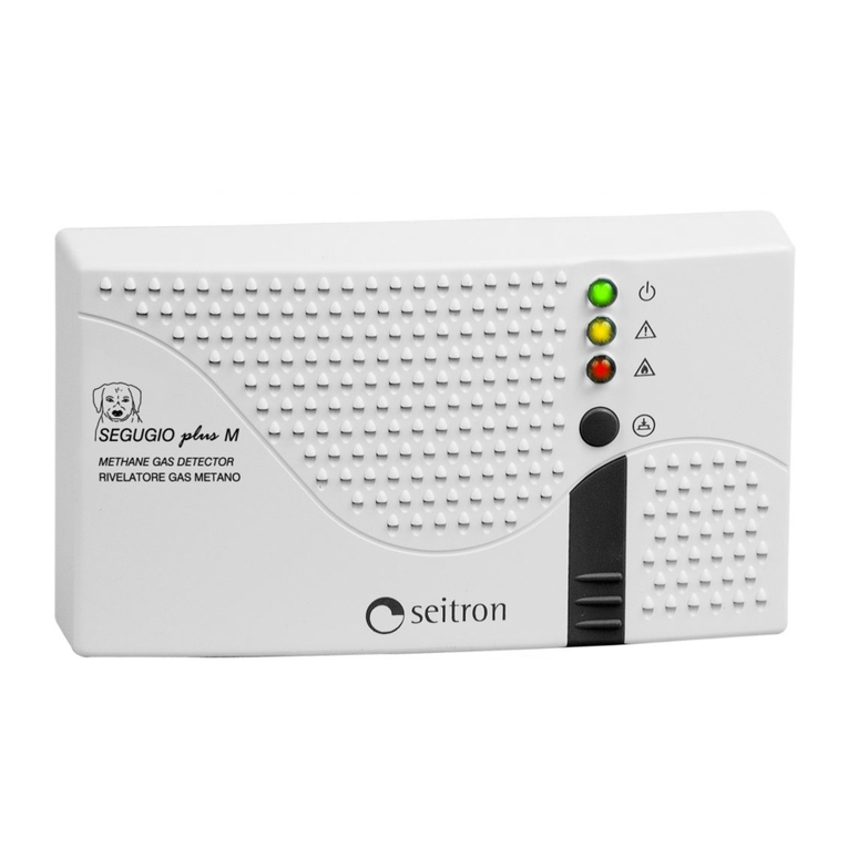
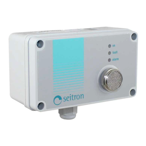
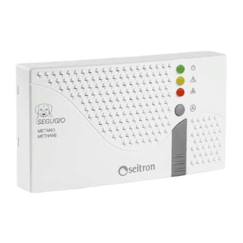
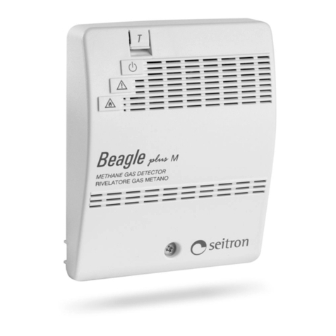
Questo rilevatore (Fig. 1) è un apparecchio per la rilevazione
della presenza di gas infiammabile. In presenza di gas in
concentrazione molto inferiore alla soglia di pericolosità,
attiva una luce rossa e dopo un ritardo di circa 5 secondi,
aziona una suoneria e un relè che interrompe l'erogazione
del gas.
Presenta inoltre un sistema di autodiagnostica per verificare
l'affidabilità del sensore. Per verificare il buon funzionamento
del rilevatore, premere il tasto 'T' (Test): si accenderà il led
rosso e, dopo circa 5 secondi anche la cicalina ed il relè fino
a quando non verrà rilasciato il tasto. Il dispositivo è dotato
di una linea di ritardo che evita l'intervento del sistema di
allarme (dovuto al tempo di stabilizzazione del sensore)
quando il dispositivo viene alimentato o, al ripristino, dopo
un'interruzione della tensione di rete. Dopo tale tempo di
ritardo, circa 50 secondi, si spegne la spia gialla e la spia
rossa e il dispositivo si porta in condizioni normali di lavoro.
Questo dispositivo prevede, tramite l’accensione della spia
gialla, la segnalazione di:
- sensore guasto;
- malfunzionamento dell'apparecchio.
Quando si accende contemporaneamente la spia gialla di
sensore guasto e la spia rossa di allarme, le possibili cause
sono:
- periodo di riscaldamento del sensore;
- malfunzionamento dell'apparecchio.
NOTE DI UTILIZZO
La rapidità di intervento dell'apparecchio è strettamente
legata al suo posizionamento nell'ambiente e al tipo di gas
da rilevare.
Per i gas 'pesanti', come il GPL, si consiglia di installare
l'apparecchio in basso (circa 0 cm dal pavimento), mentre
per i gas ‘leggeri’, come il metano, in alto (circa 0 cm dal
soffitto).
Si eviti di installare il rilevatore in posizione tale da essere
investito direttamente da fumi o vapori contenenti sostanze
in grado di alterare o di isolare il sensore del dispositivo
(esempio: non posizionare il dispositivo in corrispondenza
dei fumi grassi prodotti in cucina). Si consiglia inoltre una
periodica verifica funzionale (es.: provocare l'attivazione
dell'allarme con un batuffolo di cotone imbevuto d’alcool).
ATTENZIONE: non si deve mai provare l’apparecchio
tramite un’accendino, perché in uesto modo si
danneggia irreparabilmente il sensore.
Per effettuare l'installazione o una verifica, rimuovere la
calotta togliendo la vite presente sul frontale, (vedi Fig. 1).
Ad installazione ultimata applicare in modo visibile una
etichetta con indicata la data entro cui è necessario
sostituire il sensore, (Fig. 6).
a
ATTENZIONE
Nel chiudere il rilevatore accertarsi che le morsettiere
estraibili siano inserite correttamente (le viti delle
morsettiere devono essere rivolte verso l'alto).
Effettuare i collegamenti elettrici come da schemi proposti in
Fig. 2, Fig. , Fig. 4 oppure Fig. 5. Un rilevatore di fughe di
gas per garantire una effettiva sicurezza deve essere
abbinato ad una elettrovalvola che interrompa il flusso del
gas in caso di allarme.
Al rilevatore possono essere abbinate due tipi di
elettrovalvole:
- elettrovalvola 2 0V~ normalmente aperta;
- elettrovalvola 2 0V~ normalmente chiusa.
a
ATTENZIONE
- Utilizzare cavi di sezione minima 1,5 mm² e lunghezza
max. 50 m.
- Collegare l'apparecchio alla rete di alimentazione
tramite un interruttore onnipolare conforme alle
norme vigenti e con distanza di apertura dei contatti
di almeno 3 mm in ciascun polo.
- L'installazione ed il collegamento elettrico del
dispositivo devono essere eseguiti da personale
ualificato ed in conformità alle leggi vigenti.
- Prima di effettuare ualsiasi collegamento accertarsi
che la rete elettrica sia scollegata.
ATTENZIONE! In caso di allarme:
1) Spegnere tutte le fiamme libere.
2) Chiudere il rubinetto del contatore del gas o della
bombola del GPL.
) Non accendere o spegnere luci; non azionare
apparecchi o dispositivi alimentati elettricamente.
4) Aprire porte e finestre per aumentare la
ventilazione dell’ambiente.
Se l’allarme cessa è necessario individuare la causa
che l’ha provocato e provvedere di conseguenza.
Se l’allarme continua e la causa di presenza di gas
non è individuabile o eliminabile abbandonare
l’immobile e, dall’esterno, avvisare il servizio di
emergenza.
ITALIANO
RGDGP5MP11SE 0 592 271119
4
In the view of a constant development of their products, the manufacturer
reserves the right for changing technical data and features without prior
notice. The consumer is guaranteed against any lack of conformity according
to the European Directive 1999/44/EC as well as to the manufacturer’s
document about the warranty policy. The full text of warranty is available on
request from the seller.
TECHNICAL FEATURES
Power supply: 2 0V~ ±10% 50/60 Hz
Electric power: 1,5VA
Sensor type: SnO
2
semiconductor
Detected gas:
RGD GP5 MP11SE: LPG
RGD ME5 MP11SE: Methane
Sensitivity: 5% .. 20% L.E.L.
Output 1: 5A 250V~ SPDT relay
Signalling: Green led on: Active
Yellow led on: Fail
Red led on: Alarm
Buzzer: Alarm, (after ~ 5 seconds)
Activation delay: ~ 50 seconds
Relay activation delay: ~ 5 seconds
Sensor lifetime: 5 years
Operating temperature: 0°C .. 40°C
Storage temperature: -10°C .. +50°C
Humidity limits: 20% .. 80% RH
non condensing
Protection grade: IP 42
Case: Material: ABS V0 self-extinguishing
Color: Signal white (RAL 900 )
Size: 85 x 107 x 8 mm
(W x H x D)
Weight: ~ 260 gr.
OPERATION
This device (Fig. 1) is a flammable gas leakage domestic
detector.
When in presence of gas at a concentration much lower than
the dangerous threshold, it turns on a red indicator and,
consequently, after about 5 seconds delay, it turns on both a
buzzer and a relay which, in turn, closes the gas cut-off
electro-valve.
The detector also features an auto-diagnostic system for
checking the sensor good conditions. In order to check the
detector good operation just press the 'T' (test) key: the red
LED will be turned on, followed, after about 5 seconds, by
the buzzer and the internal relay, until the key is released.
The device is equipped with a delay line which avoids the
intervention of the alarm system (in order for the gas sensor
to heat up) whenever the device is turned on or even after a
mains black-out, as soon as the power comes back. After
such a time delay (about 50 seconds), both yellow and red
indicators turn off in order to indicate the 'active' state for the
detector itself.
When the yellow indicator is turned on (sensor fail) the
possible reasons must be searched among the following:
- sensor failure,
- detector fault.
When the yellow and the red indicators are turned on at the
same time, the possible reasons are:
- warm up time for the sensor,
- detector fault.
USE INSTRUCTIONS
Please note that the intervention delay is strictly dependant
both on a correct positioning of the detector in the room and
to the type of gas to be detected.
In case of 'heavy' gases (as for LPG) an installation in low
places is advisable (roughly 0 cm. from floor level),
meanwhile for ’light’ gases like methane in high places
(roughly 0 cm from ceiling level).
Please avoid installation in such a position that it can be
directly in the stream of smokes or vapours containing
compounds which are dangerous for the sensor health (as
an example: do not position the detector in the stream of
greasy smokes produced by cooking).
A periodic functional check is also highly advisable (through
the use of a cotton flock drenched with alcohol, for example).
WARNING: never use the gas of a cigarette lighter to
test the functionality of the detector: in this case the
internal sensor would be permanently damaged.
For installing or testing the unit, remove the screw located
on the front cover, then dismantle the plastic cover itself,
(see Fig. 1).
When installation is completed, apply the sticking label and
write on it the date before which the sensor must be
replaced, (see Fig. 6).
a
WARNING
When closing the detector please ensure that the
removable wiring terminals have been inserted with the
correct orientation (the terminals screws must be facing
upward).
Make electrical wirings as indicated in Fig. 2, Fig. , Fig. 4 or
Fig. 5. In order to grant a real safety, a gas detector must be
coupled to an electro-valve capable of blocking the gas flow
in the event of an alarm.
These electro-valves can be coupled to detector:
- 2 0V~ normally open electro-valve;
- 2 0V~ normally closed electro-valve;
a
WARNING
- Use wires with 1.5 mm² minimum section and no
longer than 50 m.
- The appliance must be wired to the electric mains
through a switch capable of disconnecting all poles
compliant to the current safety standards and with a
contact separation of at least 3 mm in all poles.
- Installation and electrical wirings of this appliance
must be made by ualified technicians and in
compliance with the current standards.
- Before wiring the appliance be sure to turn the mains
power off.
WARNING! In case of an alarm:
1) Extinguish all fire sources.
2) Close main gas valve (either methane or LPG).
) Do not turn on or off any electrical light; do not
turn on or off any electrical device.
4) Open doors and windows to increase ventilation.
If the alarm stops it is necessary to search the
possible cause and consequently provide.
In case the alarm persists and the cause of the leak
cannot be found, vacate the premises and, from
external, immediately notify the gas emergency
service.
ENGLISH
RGDGP5MP11SE 0 592 271119
5
