TELEDYNE OLDHAM SIMTRONICS OLC 10 User manual

NPO10GB-Revision I.0
OLC/OLCT 10
ANALOG GAS DETECTOR
USER
MANUAL

OLC/OLCT 10
ANALOG GAS DETECTOR
USER MANUAL
II
NPO10GB
Revision I.0
User Manuals in other languages are available on
Website https://teledynegasandflamedetection.com
Copyright July 2022 by TELEDYNE OLDHAM SIMTRONICS S.A.S.
All rights reserved. No reproduction of all or part of this document, in any form, is permitted
without the written consent of TELEDYNE OLDHAM SIMTRONICS S.A.S.
All of the information that is provided in this document is accurate to the best of our knowledge.
As a result of continuous research and development, the specifications of this product may be
changed without prior notice.
TELEDYNE OLDHAM SIMTRONICS S.A.S.
Rue Orfila
Z.I. Est – CS 20417
62027 ARRAS Cedex

OLC/OLCT 10
ANALOG GAS DETECTOR
USER MANUAL
NPO10GB
Revision I.0
III
Thank you for choosing this TELEDYNE OLDHAM SIMTRONICS instrument.
All of the necessary actions have been taken in order to ensure your complete satisfaction with
this equipment.
It is important that you read this entire manual carefully and thoroughly.
The extent of our responsibility
The company TELEDYNE OLDHAM SIMTRONICS S.A.S.,hereinafter referred to as TELEDYNE
OLDHAM SIMTRONICS throughout this document, shall not be held responsible for any
damage to the equipment or for any physical injury or death resulting in whole or in part from
the inappropriate use, installation, or storage of the equipment, which is the result of not
complying with the instructions and warnings, and/or with the standards and regulations in
force.
TELEDYNE OLDHAM SIMTRONICS does not support or authorise any business, person, or
legal entity in assuming responsibility on behalf of TELEDYNE OLDHAM SIMTRONICS, even
though they may be involved in the sale of TELEDYNE OLDHAM SIMTRONICS products.
TELEDYNE OLDHAM SIMTRONICS shall not be responsible for any damage, direct or indirect,
or for damages and interest, direct or indirect, resulting from the sale and use of any of its
products UNLESS SUCH PRODUCTS HAVE BEEN DEFINED AND CHOSEN BY TELEDYNE
OLDHAM SIMTRONICS FOR THE USE THAT THEY ARE INTENDED.
Ownership clauses
The drawings, specifications, and information herein contain confidential information that is the
property of TELEDYNE OLDHAM SIMTRONICS.
This information shall not, either in whole or in part, by physical, electronic, or any other means
whatsoever, be reproduced, copied, divulged, translated, or used as the basis for the
manufacture or sale of TELEDYNE OLDHAM SIMTRONICS equipment, or for any other reason
without the prior consent of TELEDYNE OLDHAM SIMTRONICS.
Warning
This is not a contractual document. In the best interest of its customers and with the aim of
improving performance, TELEDYNE OLDHAM SIMTRONICS reserves the right to alter the
technical features of its equipment without prior notice.
READ THESE INSTRUCTIONS CAREFULLY BEFORE THE FIRST USAGE: these instructions
should be read by all persons who have or will have responsibility for the use, maintenance, or
repair of the instrument.
This instrument shall only be deemed to be in conformance with the published performance if
used, maintained, and repaired in accordance with the instructions of TELEDYNE OLDHAM
SIMTRONICS by TELEDYNE OLDHAM SIMTRONICS personnel or by personnel authorised by
TELEDYNE OLDHAM SIMTRONICS.

OLC/OLCT 10
ANALOG GAS DETECTOR
USER MANUAL
IV
NPO10GB
Revision I.0
Important Information
The modification of the material and the use of parts of an unspecified origin shall entail the
cancellation of any form of warranty.
The use of the unit has been projected for the applications specified in the technical
characteristics. Exceeding the indicated values cannot in any case be authorized.
Catalytic sensors are susceptible to poisoning by traces of several substances. This leads to an
inhibition which can be permanent or temporary depending on the contaminant, the
concentration of the contaminant, the duration of exposure to the contaminant.
Poisoning may result from exposure to substances as:
•Silicones (e.g. Waterproofing, adhesives, release agents, special oils and greases,
certain medical products, commercial cleaning agents)
•Tetraethyl lead (e.g. Leaded petrol, particularly aviation petrol ‘avgas’)
•Sulfur compounds (sulfur dioxide, hydrogen sulfide)
•Halogenated compounds (r134a, hfo, etc.)
•Organo-phosphorus compounds (e.g. Herbicides, insecticides, and phosphate esters in
fireproof hydraulic fluids
TELEDYNE OLDHAM SIMTRONICS recommends regular testing of fixed gas detection
installations (read Chapter 4).
Guarantee
Under normal conditions of use and on return to the factory, parts and workmanship are
guaranteed for 2 years, excluding such consumables as sensors, filters, etc.
Destruction of the equipment
European Union (and EEA) only.
This symbol indicates that, in conformity with directive
DEEE (2002/96/CE) and according to local regulations, this product may not be
discarded together with household waste.
It must be disposed of in a collection area that is set aside for this purpose, for example at a site
that is officially designated for the recycling of electrical and electronic equipment (EEE) or a
point of exchange for authorized products in the event of the acquisition of a new product of the
same type as before.

OLC/OLCT 10
ANALOG GAS DETECTOR
USER MANUAL
NPO10GB
Revision I.0
V
Table of Contents
1Presentation of different versions......................................................1
1.1 Different versions available .................................................................................. 1
2Mechanical installation of different versions, dimension
and mounting ........................................................................................3
3Electrical Installation of different versions......................................5
3.1 Connection of OLC 10, OLCT 10 EXPLO or OLCT 10 SC (Semi-
Conductor) to a controller for combustible gas detection: .................. 5
3.2 Connection of two OLC 10 TWIN to a controller ......................................... 6
3.3 Connection of two OLCT 10 TOX (maximum 5) to a controller for
detection of the same toxic gas ....................................................................... 7
3.4 Connection of two OLCT 10 TOX networks (5 detectors max. per
network) for detection of two different toxic gases or
monitoring of two conjoined areas to a two-channel controller......... 8
4Maintenance ......................................................................................... 9
4.1 Periodic maintenance with an OLC 10 detector (comb. gas) ............. 9
4.2 Periodic maintenance with an OLC 10 TWIN transmitter (comb.
gas)..............................................................................................................................10
4.3 Periodic maintenance with an OLCT 10 transmitter (comb. or
toxic gas)...................................................................................................................10
4.4 Periodic maintenance with several OLCT 10 transmitters for
toxic gas ....................................................................................................................14
4.5 Sensor replacement ..............................................................................................14
5Technical specifications ...................................................................15
5.1OLC 10 / OLC 10 Twin Detector........................................................................15
5.2 OLCT 10 Explo Transmitter ...................................................................................16
5.3 OLCT 10 CO Transmitter .......................................................................................17
5.4 OLCT 10 NO Transmitter .......................................................................................18
5.5 OLCT 10 NO2 Transmitter.....................................................................................19
5.6 OLCT 10 SC Transmitter.........................................................................................20

OLC/OLCT 10
ANALOG GAS DETECTOR
USER MANUAL
VI
NPO10GB
Revision I.0
6Detail specifications for use in explosive atmospheres in
accordance with the atex 94/9/ce european directive .........21
6.1 Specifications for installation in ATEX Zone 2GD ........................................21
6.2 Metrological specifications for OLC 10 combustible gas
detector.....................................................................................................................21
6.3 Special precautions...............................................................................................21
6.4 Reactions to other combustible gases ..........................................................21
6.5 MARKING ...................................................................................................................22
7Declarations of conformity...............................................................23

OLC/OLCT 10
ANALOG GAS DETECTOR
USER MANUAL
NPO10GB
Revision I.0
1
1Presentation of different versions
The OLC 10, OLC 10 TWIN and OLCT 10CAT combustible gas detectors are detectors fitted
with catalytic sensors and intended for use in boiler rooms and parking lots.
The OLCT 10TOX gas detectors are 4-20mA transmitters equipped with electrochemical
sensors and especially designed to detect toxic gases in commercial and light industrial
applications (parking lots, boiler room, etc).
The OLCT 10 SC gas detectors are 4-20mA transmitters equipped with semi-conductor sensors
and especially designed to detect toxic or combustible gases.
1.1 Different versions available
•OLC 10: combustible gas
•OLC 10 TWIN: combustible gas
•OLCT 10 CAT: combustible gas (transmitter version, 4-20 mA output)
•OLCT 10 TOX: toxic gas (transmitter version, 4-20 mA output)
•OLCT 10 SC: toxic or combustible gas (transmitter version, 4-20 mA output)
Only OLC 10 and OLC 10 TWIN models are certified for use in ATEX zones

OLC/OLCT 10
ANALOG GAS DETECTOR
USER MANUAL
2
NPO10GB
Revision I.0

OLC/OLCT 10
ANALOG GAS DETECTOR
USER MANUAL
NPO10GB
Revision I.0
3
2Mechanical installation of different
versions, dimension and mounting
The OLC/OLCT 10 gas detectors-transmitters are mounted vertically with the cable entries
positioned downwards.
Drill two holes 104 mm apart on the base to mount the units.

OLC/OLCT 10
ANALOG GAS DETECTOR
USER MANUAL
4
NPO10GB
Revision I.0

OLC/OLCT 10
ANALOG GAS DETECTOR
USER MANUAL
NPO10GB
Revision I.0
5
3Electrical Installation of different
versions
3.1 Connection of OLC 10, OLCT 10 CAT or OLCT 10 SC to
a controller:
The controller configuration will be different based upon the use of an OLC 10 or
OLCT 10
Cable to be used: 3 conductors, 3x1 mm² LiYCY type
*analog signal 4-20 mA (I out) on OLCT 10.
1
2
3
1 2 3
e.g., CONTROLLER MX 15
Connect the 3 wires based on the
corresponding numbering on the
sensor.
Connect the 3 wires based on the
corresponding numbering on the
controller.
1= signal*
2= -
3= +
1
2
3
OLC 10
OLCT 10
EXPLO

OLC/OLCT 10
ANALOG GAS DETECTOR
USER MANUAL
6
NPO10GB
Revision I.0
3.2 Connection of two OLC 10 TWIN to a controller
Cable to be used: 3 and 4 core cable, 3x1 mm² and 4x1 mm² LiYCY type
Connect the
3
wires based on the
corresponding numbering on the
controller.
Connect the
3
wires based on the
corresponding numbering on the
first sensor.
Connect the
4
wires based on the
corresponding numbering on the
previous and the following sensor.
1
2
3
1= signal
2= -
3= +
IN
4 3 2 1
MX 15 CONTROLLER
OUT
4 3 2 1
IN
OUT
4 3 2
4 3 2 1
1 2 3
2
1
3

OLC/OLCT 10
ANALOG GAS DETECTOR
USER MANUAL
NPO10GB
Revision I.0
7
3.3 Connection of two OLCT 10 TOX (maximum 5) to a
controller for detection of the same toxic gas
Cable to be used: One pair (0.75 mm²) screened cable
Notes : The free terminals allow the connection of another network of OLCT 10 TOX.
COMMENTS:
the number of OLCT 10 toxic gas detectors shall be configured on the controller,
the signal read by the controller is the average of the “n” detectors. As a result, a
signal fault may not be detected.
In the event that 2 networks are used, it is cost-effective to use a single cable (2 pairs) subject to
compliance with wiring as follows:
IN
1 2 3
IN OUT
CONTROLLER MX15 for example
1 3
3 1 3 1 3 1 3
Connect
the
2
wires based on the
corresponding numbering on the
first sensor.
Connect
the
2
wires based on the
corresponding numbering on the following
sensor.
Connect the
2
wires based on the
corresponding numbering on the
controller.
1
3
1
3
1
3
1= Iout
3= +Vdc
OLCT 10 TOX
3 1 3 1

OLC/OLCT 10
ANALOG GAS DETECTOR
USER MANUAL
8
NPO10GB
Revision I.0
3.4 Connection of two OLCT 10 TOX networks (5 detectors
max. per network) for detection of two different toxic
gases or monitoring of two conjoined areas to a two-
channel controller
Cable to be used: Two pairscreened cable (0.75 mm²)
Controller with 2 channels at minimum
Information for this example:
•channel 1 is a channel connected to two sensors for detection of CO
•channel 2 is a channel connected to two sensors for detection of NO
•detector 1 (CO) also acts as junction box for detector 2 (NO)
•detector 2 (NO) also acts as junction box for detector 3 (CO)
•detector 3 (CO) also acts as junction box for detector 4 (NO)
Example: one zone, 2 gases
Detector 1
Detector 2
Detector 3
Detector 4
Cable with 4
wires
Channel 1
Channel
2
MX 32
controller

OLC/OLCT 10
ANALOG GAS DETECTOR
USER MANUAL
NPO10GB
Revision I.0
9
4Maintenance
Caution: The actions described in this paragraph are intended for authorized and
trained individuals who are likely to question the detection safety.
Gas detection instruments are potential life-saving devices. Recognizing this fact, TELEDYNE
OLDHAM SIMTRONICS recommends that a functional “bump” test be performed on every
fixed gas-monitoring instrument as part of a regular maintenance program. A functional test is
defined as a brief exposure of the detector to a concentration of gas(es) in excess of the lowest
alarm set-point for each sensor for the purpose of verifying sensor and alarm operation and is
not intended to be a measure of the accuracy of the instrument.
Bump test frequency depends on application, field conditions, exposure to gas, sensor
technology, and environmental conditions. For new installations it may be prudent to carry out
bump tests frequently at first, increasing the time intervals as confidence grows with experience
in the installation concerned, on the basis of the maintenance record. The maintenance test
interval should not be more than 3 months.
If an instrument fails to operate properly during any functional “bump” test, a full instrument
calibration should be performed successfully prior to use. Calibration frequency will be based
on bump tests results. However it cannot be more than 12 months.
These recommendations are based on safe work procedures, industry best practises, and
regulatory standards to ensure worker safety. TELEDYNE OLDHAM SIMTRONICS is not
responsible for setting safety practices and policies.
4.1 Periodic maintenance with an OLC 10 detector (comb.
gas)
•The “maintenance” position was selected on the controller in order to disable its relays
(see manual of relevant product)
Make sure the detector is in clean air - otherwise inject zero air on the detector (with
calibration kit) with a flow rate of 60 l/h, then wait for the stabilisation of
measurement

OLC/OLCT 10
ANALOG GAS DETECTOR
USER MANUAL
10
NPO10GB
Revision I.0
•Perform the zero setting of the controller (see manual of relevant product)
•Now inject the calibration gas (flow rate 60l/h) into the OLC 10 sensor and wait for
signal stabilisation on the controller display
•If necessary, calibrate the sensitivity using the “S” potentiometer of the controller (see
manual of relevant product)
•Upon completion of calibration: wait for the “return to zero” on the controller display
•Return to the “normal” mode of the controller (see manual of relevant product)
4.2 Periodic maintenance with an OLC 10 TWIN transmitter
(comb. gas)
•The procedure is almost identical to point 1 (OLC 10), with the exception of sensitivity
adjustment which is performed on the OLC 10 TWIN detector that is less sensitive.
•To determine the least sensitive detector, inject gas on the two detectors, one after the
other (wait for the signal to read zero). The detector that gives the lowest measurement is
the less sensitive.
4.3 Periodic maintenance with an OLCT 10 transmitter (comb.
or toxic gas)
•It is required that the kit provided by TELEDYNE OLDHAM SIMTRONICS be used (P/N
6147872)
•Remove the end-cap that provides access to settings, located on the right side of the
sensor
•Connect this kit on the male plug of the circuit, as indicated below:

OLC/OLCT 10
ANALOG GAS DETECTOR
USER MANUAL
NPO10GB
Revision I.0
11
MAINTENANCE CONNECTOR WIRES:
+VDC/red + power supply
- 4-20mA/blue - of voltage, image of 4-20mA
Read on the voltmeter
400mV for 4mA and
2000mV for 20mA
+ 4-20mA/green + of voltage, image of 4-20mA
S Signal /yellow signal from 0mV to 1600mV for zero
and sensitivity setting Voltmeter
Ref 2,5V/gray zero reference for reading of signal
from 0mV to 1600mV
GND/black electronic circuit ground
•Toggle the changer-over (under the connector) on «CAL» position (to the right)
Caution:after 9 minutes the transmitter automatically returns to normal operation!
(only version OLCT 10 explo)
Reminder:make sure the detector is in clean air - otherwise inject zero air or
nitrogen on the sensor at a flow rate of 60 l/h – and wait for the stabilisation of
the measurement given by the voltmeter.
•Set the ZERO using the zero potentiometer to read 0 mV on the voltmeter
ZERO (4mA)
potentiometer
SENSITIVITY (20mA)
potentiometer
S Signal
+VDC
+4-20 mA
- 4-20 mA
Ref 2.5V
GND
V
CHANGER-OVER
Voltmeter

OLC/OLCT 10
ANALOG GAS DETECTOR
USER MANUAL
12
NPO10GB
Revision I.0
•Now inject the calibration gas (60l/h), wait for the signal stabilisation on the voltmeter
•If required, set the sensitivity using the “S” potentiometer to read 1,600mV for the full
scale (corresponding to 20mA)
Note: if you use a gas concentration lower than 100% of the scale, calculate (rule of three) and
adjust to obtain the corresponding value (from 0 to 1600 mV)
•Stop calibration gas injection (remove the calibration cup)
•Wait for the “return to zero” on the voltmeter
•Again toggle the changer-over to the normal position (to the left)
Notes regarding the OLCT 10 version for combustible gases:
•The transmitter controls an “ambiguity resolution” function: if the sensor detects a gas
concentration over 100% LEL (20 mA), it will be locked on a signal of 23.2 mA
acknowledgeable through power supply shut-off or toggling of maintenance switch. The
ambiguity resolution may be automatically acknowledged if the PPS3 points are short-
circuited.
•Upon switching on, the output signal is set to 2mA during the 60-second stabilisation
time.
PPS3

OLC/OLCT 10
ANALOG GAS DETECTOR
USER MANUAL
NPO10GB
Revision I.0
13
4.4 Reactions to other combustible gases
It is recommended to calibrate the detector with the gas to be measured. When the user wishes
to calibrate it with another gas than that detected and factory programmed, refer to the table
below, using the recommended gas and corresponding coefficient.
When a VQ1 type sensor is used, the coefficients are as follows: (concern detector PN as
6513559, 6513566, OLCT10-001, OLCT10-002, OLCT10-003, OLCT10-004 and
OLCT10-005)
Gas
Empirical
formula
LEL
LSE
Vapour
density
Coefficient
CH4
Coefficient
H2
Coefficient
But
Butane C4H10 1.5% 8.5 % 2 1.9 1.25 1.0
Hydrogen H24.0% 75.6% 0.069 1.0
Methane CH45.0% 15.0% 0.55 1.0 0.75 0.55
Propane C3H82.0% 9.5 1.6 1.55 0.85
Gas recommended for the calibration.
table 1
When a 4F type sensor is used, the coefficients are as follows: (concern detector PN as
6513684, 6513685, OLCT10-AP-001, OLCT10-AP-002, OLCT10-AP-003, OLCT10-AP-
004 and OLCT10-AP-005)
Gas
Empirical
formula
LEL
LSE
Vapour
density
Coefficient
CH4
Coefficient
H2
Coefficient
But
Butane C4H10 1.5% 8.5 % 2 1.9 1.25 1.0
Hydrogen H24.0% 75.6% 0.069 1.0
Methane CH45.0% 15.0% 0.55 1.0 0.75 0.55
Propane C3H82.0% 9.5 1.6 1.55 0.85
Gas recommended for the calibration.
table 2

OLC/OLCT 10
ANALOG GAS DETECTOR
USER MANUAL
14
NPO10GB
Revision I.0
Example (first line in the table 1): calibration of a “Propane” detector with a calibration gas of
1% butane volume
Value to be displayed:
1% (injected butane) x 100 x0.85 (butane/acetone coefficient) = 57% LEL
1.5% (LEL butane)
Note:
LEL varies based on sources.
The coefficients are accurate at ±15%
4.5 Periodic maintenance with several OLCT 10 transmitters
for toxic gas
Use the procedure described in the previous paragraph. However:
•Start with the last transmitter in the loop in relation to the controller
•Calibrate each transmitter in the loop and end with the first
4.6 Sensor replacement
•Sensor has to be replaced as a result of impracticable calibration or as a preventive
measure.
•Perform a new calibration after a sensor replacement.
This manual suits for next models
11
Table of contents
Other TELEDYNE OLDHAM SIMTRONICS Gas Detector manuals

TELEDYNE OLDHAM SIMTRONICS
TELEDYNE OLDHAM SIMTRONICS Everywhereyoulook GD10-P00 User manual

TELEDYNE OLDHAM SIMTRONICS
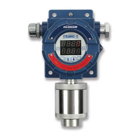
TELEDYNE OLDHAM SIMTRONICS iTRANS 2 User manual

TELEDYNE OLDHAM SIMTRONICS
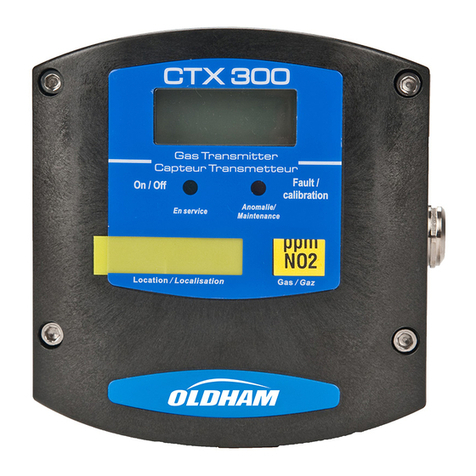
TELEDYNE OLDHAM SIMTRONICS CTX 300 User manual

TELEDYNE OLDHAM SIMTRONICS
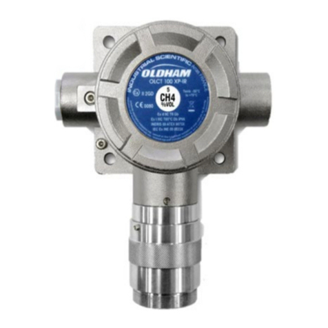
TELEDYNE OLDHAM SIMTRONICS OLC User manual

TELEDYNE OLDHAM SIMTRONICS
TELEDYNE OLDHAM SIMTRONICS OLCT 80 d User manual