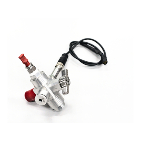
Spectronik PRREG User manual

MINIATURE GAS PRESSURE REGULATOR
PRREG
USER GUIDE
VERSION 2.1 MARCH 2022

Failure to follow these safety instructions could result in gas leakage, injuries,
damage to the gas pressure regulator (PRREG) or other property.Read all the safety information
below before using PRREG.
Handling Handle PRREG with care.PRREG is not designed for extreme conditions, rough handling, vibration,
shock or drop.Keep PRREG away from heat, flame, strong sunlight, water, dust, soil or mud.Do not use a
damaged PRREG.
Repairing Do not troubleshoot, disassemble or tamper with PRREG.Do not attempt to repair or replace any
component by yourself.
Hydrogen Follow all local rules and regulations for safe handling, storage and usage of Hydrogen gas.Do not
smoke when operating PRREG.It is recommended to operate in awell ventilated environment.
Pressure Never operate beyond PRREG’s rated inlet pressure of 350bar.
Connectors and ports Never force a connector into a port or apply excessive pressure.If the connector and port
do not join with reasonable ease, they probably do not match.Check for obstructions and ensure that the
connector matches the correct port.
High-consequence activities PRREG is a customized system with pending safety tests and certifications. It is not
intended for use where the failure of the system could lead to death, personal injury or severe environmental
damage.
Disclaimer Every effort has been made to ensure that the information in this manual is accurate.This manual
serves to adequately recommend safe operating procedures, but shall not be treated as comprehensive.Do not
use PRREG in any other way than the one recommended in this manual.Spectronik reserves the right to change
system specifications, appearance or discontinue the product at any time.
Warranty Spectronik warrants the included hardware product and accessories against defects in materials and
workmanship for 1 year after delivery. Spectronik does not warrant against normal wear and tear, nor damage
caused by accident or abuse.
To obtain service, contact support@spectronik.com
SAFETY, HANDLING & SUPPORT
WARNING:
© 2022 Spectronik Pte. Ltd., All Rights Reserved.
Spectronik, the ‘S’ logo, and PROTIUM are registered trademarks of Spectronik Pte. Ltd.

Item Description
1PRREG 6Gas outlet port
NPT ¼ to PU 6mm
2On/Off manual valve 7Refueling port with cap
M12 x 1.25
3Connector to carbon fiber cylinder
M18 x 1.5 8Refueling adapter
4Gas pressure transducer socket 9Threaded connector to refueling hose
M12 x 1.25
5
Gas pressure transducer
NPT 1/8 (to PRREG)
M12 x 1 (to receptacle)
10 Threaded connector to refueling port
M12 x 1.25
1OVERVIEW
CHAPTER 1 | OVERVIEW
* ID16 CS3 Viton O-ring may or may not be required depending on user’s gas cylinder thread. Included as
spare part in the shipment.
2
1
3
4
5
6
8
9
10
*
7

Item Description
11 Gas pressure transducer receptacle
M12 x 1 14 Threaded socket to Hydrogen source
NPT 1/4
12 Stainless steel refueling hose 15 Alternative gas outlet port (Optional)
M24 x 1.5 to M5 female
13 Mating socket to (9) M12 x 1.25
CHAPTER 1 | OVERVIEW
11
13
12
14
15

PRREG
Gas media Hydrogen
Rated inlet pressure 350bar
Min inlet pressure 10bar
Gas outlet pressure (@ rated flow) 0.45-0.75bar (factory set during order)
Max outlet pressure (@ zero flow) Gas outlet pressure + 0.3bar
Rated flow rate 40 SLPM
Operating temperature [-20,85]oC
Operating lifetime 10,000 cycles
Outer body material Al 2A14-T6
Core internal material SS 316/ H62/ TC4
Core sealing material PTFE
Sealing gasket material NBR
Dimension 75 x 85 x 58 mm
Weight 200g
Connection to gas cylinder M18 x 1.5
Connection to pressure sensor NPT 1/8
Connection to refueling hose M12 x 1.25
Gas outlet connector NPT 1/4 to PU 6mm
Optional (M24 x 1.5 to M5 female)
2SPECIFICATIONS
CHAPTER 2 | SPECIFICATIONS

1. Visually check PRREG for obvious cracks or other physical damage.Warning:never use a faulty regulator.
2. Ensure that On/Off manual valve (2) is in the Off state (fully clockwise).Do not over-tighten.
3. Ensure that gas pressure transducer (5) is securely connected. If you did not purchase the pressure
transducer, then ensure that the pressure transducer port is sealed with the plug provided.
4. Connect your desired gas output connector at (6), make sure that it is blocked at this stage, using either a
valve or blocker.
5. Connect PRREG to the carbon fiber cylinder by manually turning the threaded connector (3) into its
corresponding female socket at the cylinder neck.There is no need to apply excessive force at the end of the
turns.The carbon fiber cylinder is now ready for gas filling.Note:an ID16 CS3 Viton O-ring (provided) may or
may not be needed depending on your carbon fiber cylinder thread design.
1. Prepare the necessary adapter to link (14) to your Hydrogen source.This adapter is not provided due to the
different connector standards of Hydrogen source cylinders worldwide.
Warning:the pressure gauge provided has amaximum pressure of 25MPa.It is assumed that the Hydrogen
source will be standard industrial steel cylinder with pressure of less than 20MPa and that filling the carbon
fiber cylinder will be by means of pressure cascade.If you are connecting directly to a gas booster pump or
higher source pressures, change the pressure gauge or bypass it completely.At any time, do not operate
higher than 35MPa.
2. Connect (13) to (9).
3. Open the refueling cap (7). Keep it in asafe place, do not lose it.Connect (10) into the refueling port of
PRREG.Do not use excessive force at the end of the turns.
4. Turn on your Hydrogen source.
5. Slowly turn On the manual valve (2) by turning it anti-clockwise.Hissing sound can be heard as gas rushes in
from the source into the carbon fiber cylinder. Continue turning the valve anti-clockwise until it is fully opened
(i.e. cannot be turned anymore).Do not use excessive force at the end of the turns.
6. The gas will now fill into the carbon fiber cylinder until it reaches equilibrium with the source.
7. If you are using agas booster pump, it can now be turned on.
8. At the end of the filling process, turn off your Hydrogen source.Close the manual valve (2) by turning it fully
clockwise.Caution: at this point, there is still high pressure gas remaining in the refueling hose.Remove your
blocker at (6) to release the remaining gas through the PRREG low pressure gas outlet port.
9. Once all the gas is released, fully remove (10) from the refueling port and put back the refueling cap (7).
10. The carbon fiber cylinder is now ready for usage.
3OPERATING PROCEDURES
Filling the Carbon Fiber Cylinder
SETTING UP PRREG
CHAPTER 3 | OPERATING PROCEDURES

1. Remove the blocker at (6) that was in place during gas filling process.
2. Connect the gas outlet at (6) to your desired application, e.g. to the inlet of the supply valve of a fuel cell
system.
3. Open the manual valve (2) by turning it anti-clockwise slowly until the end.Gas from inside the carbon fiber
cylinder will now flow out through (6).
4. To turn off the gas at the end of usage, shut off the manual valve (2) by turning it clockwise.
•Wear safety goggles and gloves at all times.
•Ensure connections are firm and secure, but do not use excessive force to over-tighten.
•Never operate PRREG at inlet pressure beyond 350bar.
•Carbon fiber cylinder will become warm when filled with Hydrogen gas.Never fill a carbon fiber cylinder too
quickly.If you are using a booster pump, it is advisable to pause the filling process every 30-50bar to prevent
over temperature.
When not in use, keep PRREG in its original box and store it in a cool, dry place.
Using the filled Carbon Fiber Cylinder
Reminder
Storage
CHAPTER 3 | OPERATING PROCEDURES

4.1 FEATURES AND APPLICATIONS
•Stainless steel 316 body
•Welded configuration without sealing o-rings
•10-90% proportional voltage output
•Voltage reversal protection
•Hydrogen gas pressure measurement
•Hydraulic system pressure measurement
4.2 TECHNICAL SPECIFICATIONS
•Pressure range: 0-50 MPaG
•Output voltage (Io): 0.5-4.5VDC
•Precision (including non-linearity, hysteresis, repeatability and
calibration error, 25oC and Vcc 24VDC): +/-0.5% F.S.
•Long term stability: +/-0.25% F.S. per year
•Pressure cycling: >= 5 x 10⁶
•Operating temperature: -40 to 120oC
•Storage temperature: -40 to 105oC
•Over pressure: 1.5X
•Burst pressure: 2X
•Response time: 10ms
•Supply voltage (Vcc): 4.75-5.25VDC
•Output load resistance: >= 10k.ohm
•Over voltage: 16VDC
•Reverse over voltage: -16VDC
•Insulation resistance: >= 20M.ohm @ 100VDC
•Ingress protection: IP65
•Vibration: X/Y/Z, 20g, sine 11ms
•Shock: 10g, 5-2000Hz
4GAS PRESSURE TRANSDUCER
CHAPTER 4 | GAS PRESSURE TRANSDUCER

CHAPTER 4 | GAS PRESSURE TRANSDUCER
4.3 NOTES
•Ensure that all system connections are secure and leak free. Hydrogen leakage may cause fire
or explosion in extreme cases.
•If the pressure port of the transducer is blocked by a foreign object, do not use a sharp tool to
clear the passage. It is recommended to dissolve the foreign object in a solvent instead.
•Do not tamper with the device. Contact us for re-calibration purposes.
Signal
(white)
5V+
(brown)
5V-
(blue) NC
1/8NPT
10.0
53
M12x1
Ø 14
V
Dimensions in mm
1. Pin definition
2. Wiring diagram
Shield
Load Power
Supply
Table of contents
Other Spectronik Controllers manuals
Popular Controllers manuals by other brands
elsner elektronik
elsner elektronik KNX R1-B4 compact 16 A Installation and adjustment
TRU Components
TRU Components MS-35 operating instructions

Panasonic
Panasonic FP7 Series user manual
Stahls
Stahls Hotronix XRF2-IQ Replacement guide
Samson
Samson 3274 Mounting and operating instructions
Digital Video Lab
Digital Video Lab DejaVu user manual
