1 Contents
Elsner Elektronik GmbH • Sohlengrund 16 • 75395 Ostelsheim • Germany
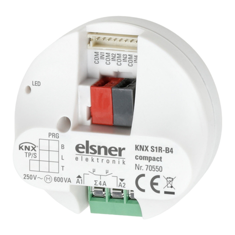
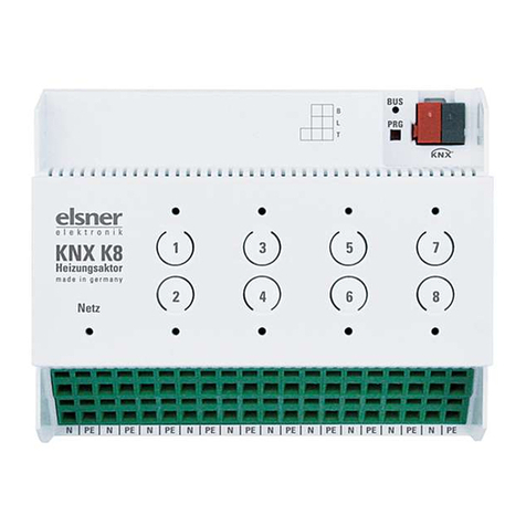
Actuator KNX R1-B4 compact 16 A • from application 1.0
Version: 28.05.2020 • Subject to technical changes. Errors excepted.
1. Description ........................................................................................... 3
1.0.1. Scope of delivery .......................................................................................... 3
1.1. Technical specification ............................................................................................. 3
2. Installation and start-up ....................................................................... 4
2.1. Installation notes ...................................................................................................... 4
2.2. Safety notice for automatic functions .................................................................... 5
2.3. Connection ................................................................................................................ 6
2.3.1. Connection examples output ....................................................................... 7
2.4. Instructions for assembly and operational start-up. ............................................. 8
3. Addressing of the device at the bus .................................................... 8
4. Disposal ............................................................................................... 8
5. Transfer protocol ................................................................................. 9
5.1. List of all communication objects ........................................................................... 9
6. Setting parameters ............................................................................ 10
6.1. Behaviour on power failure/ restoration of power .............................................. 11
6.2. General settings ..................................................................................................... 11
6.3. Switch function ....................................................................................................... 11
6.3.1. Relationship between logic operation – timer switch – Block ................. 12
6.3.2. Linking ......................................................................................................... 13
6.3.3. Switch on and off delay .............................................................................. 13
6.3.4. Staircase time switch .................................................................................. 14
6.3.5. Block function .............................................................................................. 15
6.3.6. Scenes ......................................................................................................... 15
6.4. Inputs ....................................................................................................................... 16
6.4.1. Input As a bus button ................................................................................. 16
6.4.2. Input as actuator ......................................................................................... 19
6.4.3. Control modes for drive control ................................................................ 20


