Spectronik PROTIUM-2000 User manual

PROTIUM-2000
FUEL CELL SYSTEM
USER GUIDE
VERSION 3.0 DECEMBER 2022

Failure to follow these safety instructions could result in fire, electric shock, other
injuries, or damage to PROTIUM-2000 Fuel Cell System (PROTIUM-2000)or other property.Read
all the safety information below before using PROTIUM-2000.
Handling Handle PROTIUM-2000 with care.It is made of thin sheet metal, graphite, and plastic and has sensitive
electrochemical membrane and components inside.PROTIUM-2000 is not designed for extreme conditions,
rough handling, vibration, shock or drop.Keep PROTIUM-2000 away from heat, flame, strong sunlight, water,
dust, soil or mud.Do not use adamaged PROTIUM-2000.
Repairing PROTIUM-2000 is assembled under high compression.Do not disassemble or tamper with PROTIUM-
2000.Do not troubleshoot, repair or replace any component by yourself.
Hydrogen Use only high purity (99.999%) dry Hydrogen gas with PROTIUM-2000.Hydrogen is acolorless,
odorless and highly flammable gas.It is non-toxic but can cause asphyxiation. Follow all local rules and regulations
for safe handling, storage and usage of Hydrogen gas.Do not smoke when operating PROTIUM-2000.
Ventilation Operate PROTIUM-2000 in awell ventilated environment.Fresh air intake for the fuel cell oxidant
blower, cooling air entry from the front of the protective mask, and hot air exit from the cooling fans shall not be
obstructed or restricted.
Purging PROTIUM-2000 periodically flushes its anode during operation, releasing Hydrogen gas and water from
the Hydrogen gas outlet.Do not block the Hydrogen gas outlet. Do not bring flame or electric spark close to the
Hydrogen gas outlet. It is advisable to attach alonger gas tubing to the Hydrogen gas outlet connector and safely
guide the purge exhaust far away from the fuel cell.
CAUTION:
always put the Hydrogen gas outlet tubing behind the cooling fan and never in front of
the fuel cell stack.Purged Hydrogen mixed with air intake into the fuel cell’s cathode channels may
cause fire and irreversible damage to the fuel cell.
Connectors, ports and buttons Never force a connector into a port or apply excessive pressure to a button. If
the connector and port do not join with reasonable ease, they probably do not match.Check for obstructions and
ensure that the connector matches the correct port.
Disposal and recycling As PROTIUM-2000 contains electronic components, it must be disposed of separately
from household waste.When PROTIUM-2000 reaches its end of life, follow local laws and regulations for proper
disposal and recycling options.
High-consequence activities PROTIUM-2000 is a customized system with pending safety tests and
certifications. It is not intended for use where the failure of the system could lead to death, personal injury or
severe environmental damage.
Disclaimer Every effort has been made to ensure that the information in this manual is accurate.This manual
serves to adequately recommend safe operating procedures, but shall not be treated as comprehensive.Do not
use PROTIUM-2000 in any other way than the one recommended in this manual.Spectronik reserves the right to
change system specifications, appearance or discontinue the product at any time.
Warranty Spectronik warrants the included hardware product and accessories against defects in materials and
workmanship for the first 30 days after delivery.Spectronik does not warrant against normal wear and tear, nor
damage caused by accident or abuse.
To obtain service, contact support@spectronik.com
© 2022 Spectronik Pte. Ltd., All Rights Reserved.
Spectronik, the ‘S’ logo, and PROTIUM are registered trademarks of Spectronik Pte. Ltd.
SAFETY, HANDLING & SUPPORT
WARNING:
1OVERVIEW
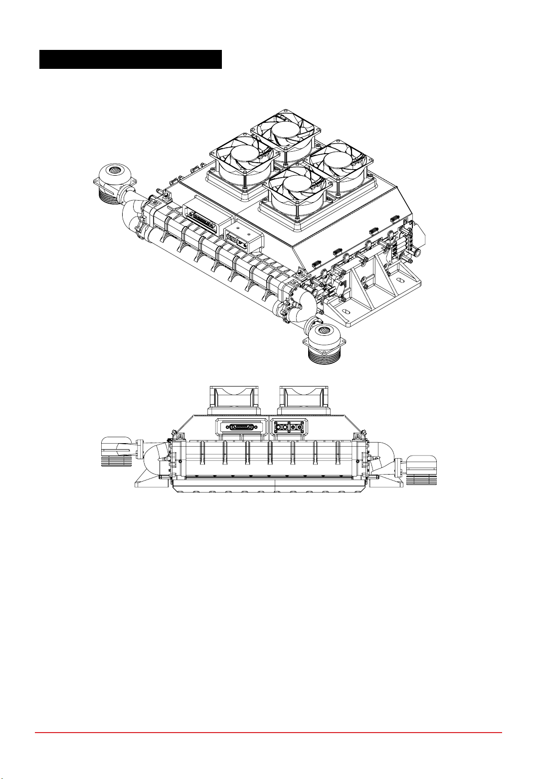
1.1 PROTIUM-2000 SYSTEM OVERVIEW
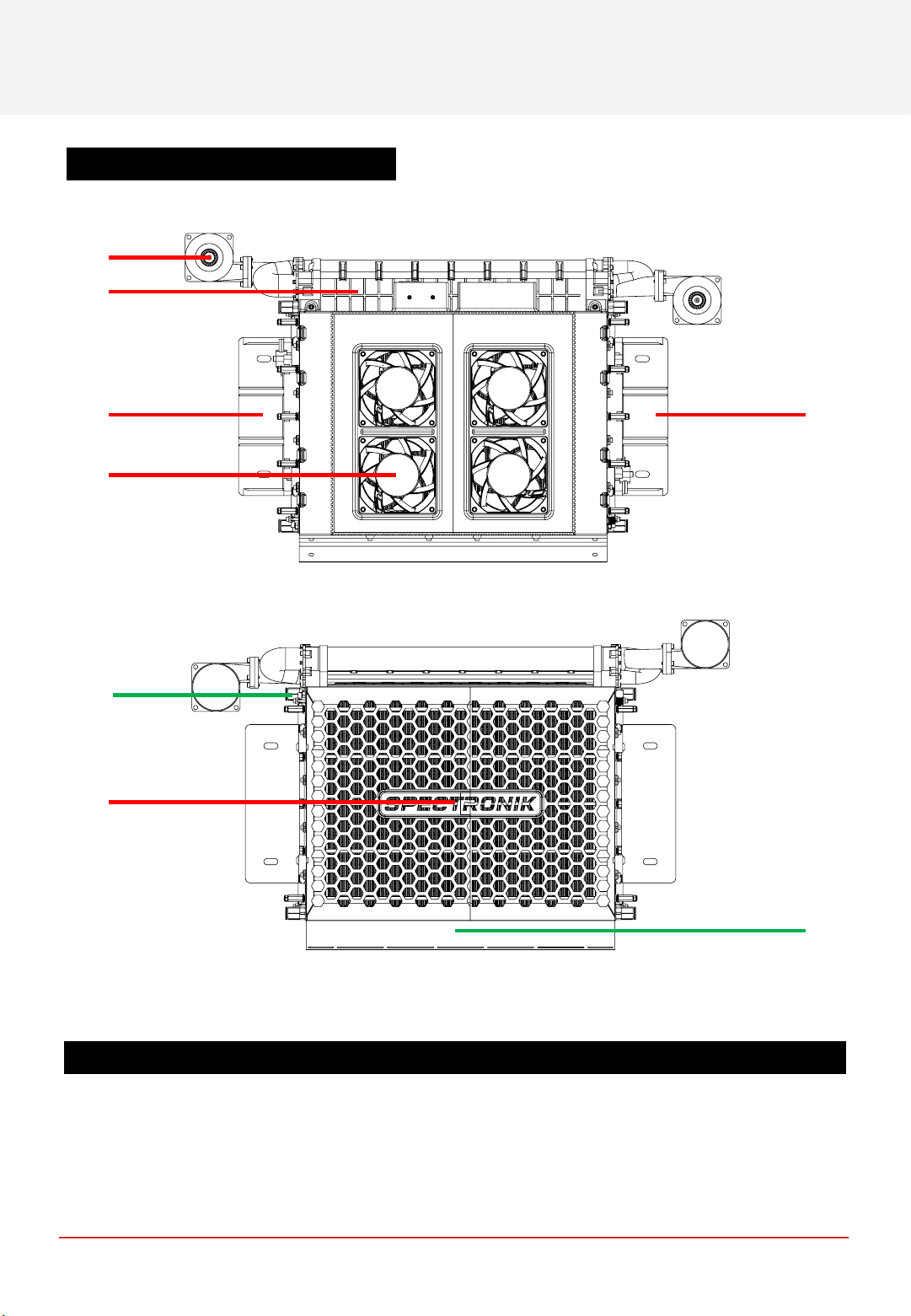
Figure 1.1.1 Top view of PROTIUM-2000
Figure 1.1.2 Bottom view of PROTIUM-2000
ITEM DESCRIPTION
1. Oxidant blower (x2) 5. Cooling fan (x4)
2. Oxidant flow manifold 6. Protective mask
3. Mounting plate (left) 7. Cathode outlet duct
4. Mounting plate (right)
43
1
2
5
6
7
11
CHAPTER 1 | OVERVIEW
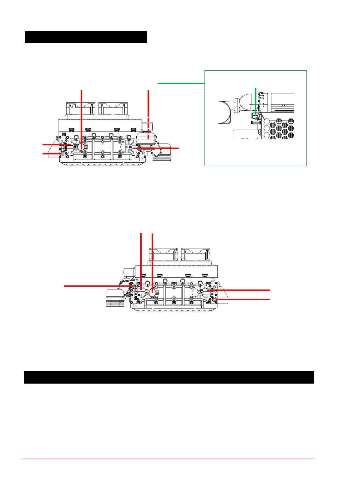
ITEM DESCRIPTION
8. Gas pressure sensor 1 13. Gas pressure sensor 2
9. H2 supply valves (right) 14. H2 supply valves (left)
10. H2 gas inlet connector (right) 15. H2 gas inlet connector (left)
11. H2 gas outlet connector (right) 16. H2 gas outlet connector (left)
12. H2 purge valves (right) 17. H2 purge valves (left)
Figure 1.1.3 Right view of PROTIUM-2000
Figure 1.1.4 Left view of PROTIUM-2000
1.1 PROTIUM-2000 SYSTEM OVERVIEW
13
16
17
14
15
8
9
10 12
11 11
Can also be seen more
clearly in Fig 1.1.2
CHAPTER 1 | OVERVIEW
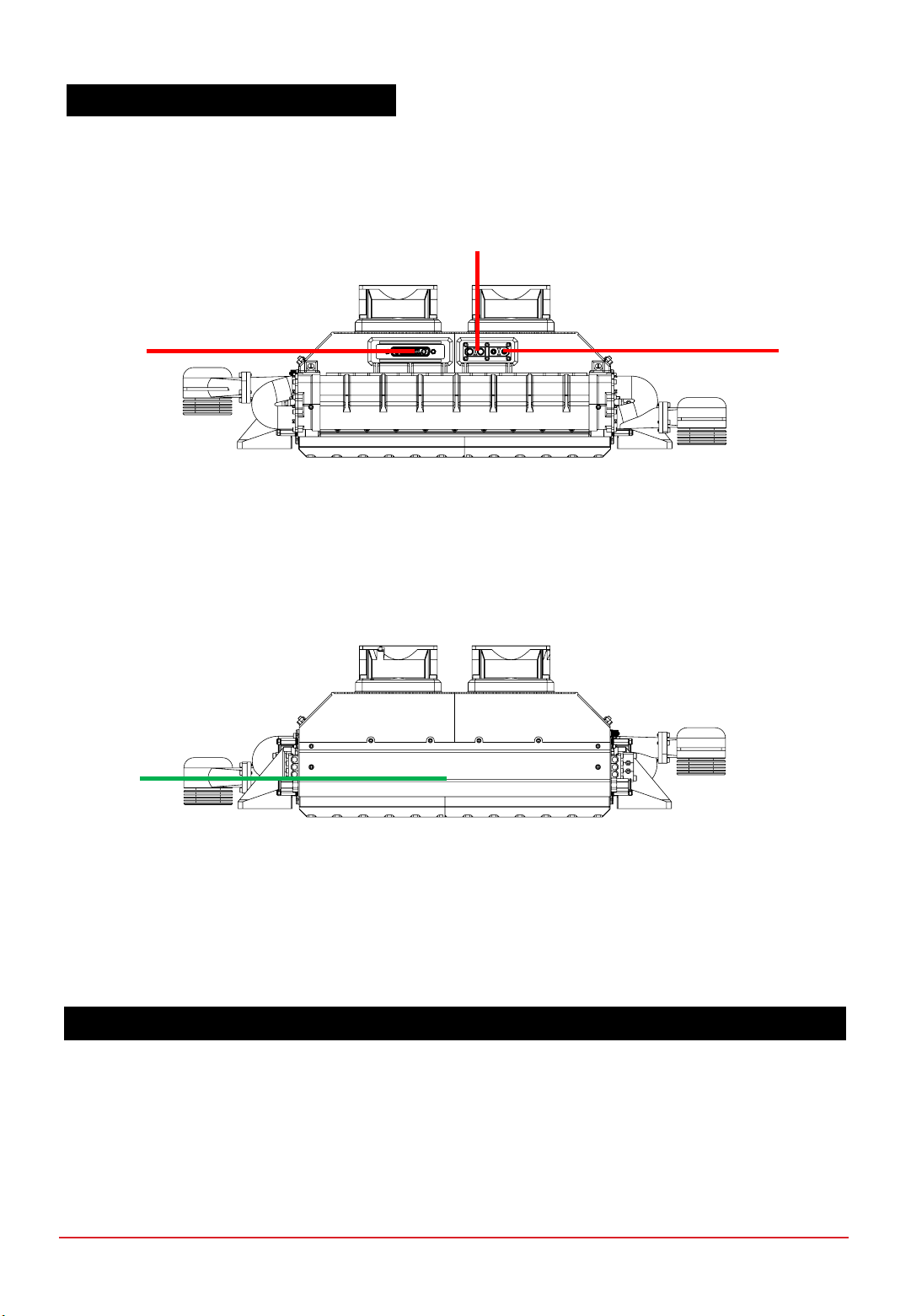
ITEM DESCRIPTION
18. Power/Signal receptacle 20. Stack power output (-ve)
19. Stack power output (+ve)
1.1 PROTIUM-2000 SYSTEM OVERVIEW
Figure 1.1.5 Front view of PROTIUM-2000
Figure 1.1.6 Back view of PROTIUM-2000
18 20
19
7
(Can also be
in Fig 1.1.2)
CHAPTER 1 | OVERVIEW
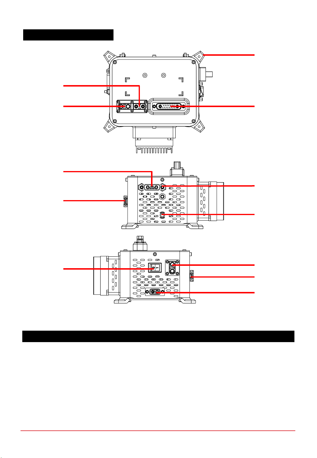
Figure 1.2.1 Top, Left and Right views of Electronic Controller
ITEM DESCRIPTION
21. Mounting hole (x4) 27. On/Off push button
22. Stack power output (+ve)28. Status LED
23. Stack power output (-ve)29. Balance-of-plant (BOP) switch
24. Power/Signal header 30. Load connector (XT-90 female)
25.
Gas pressure transducer receptacle
(Only used with purchase of Spectronik
Miniature Gas Pressure Regulator)
31. Telemetry transmitter port
26. Programming port 32. External power supply receptacle
21
24
23
22
29 30
31
32
1.2 ELECTRONIC CONTROLLER
26
27
28
25
CHAPTER 1 | OVERVIEW
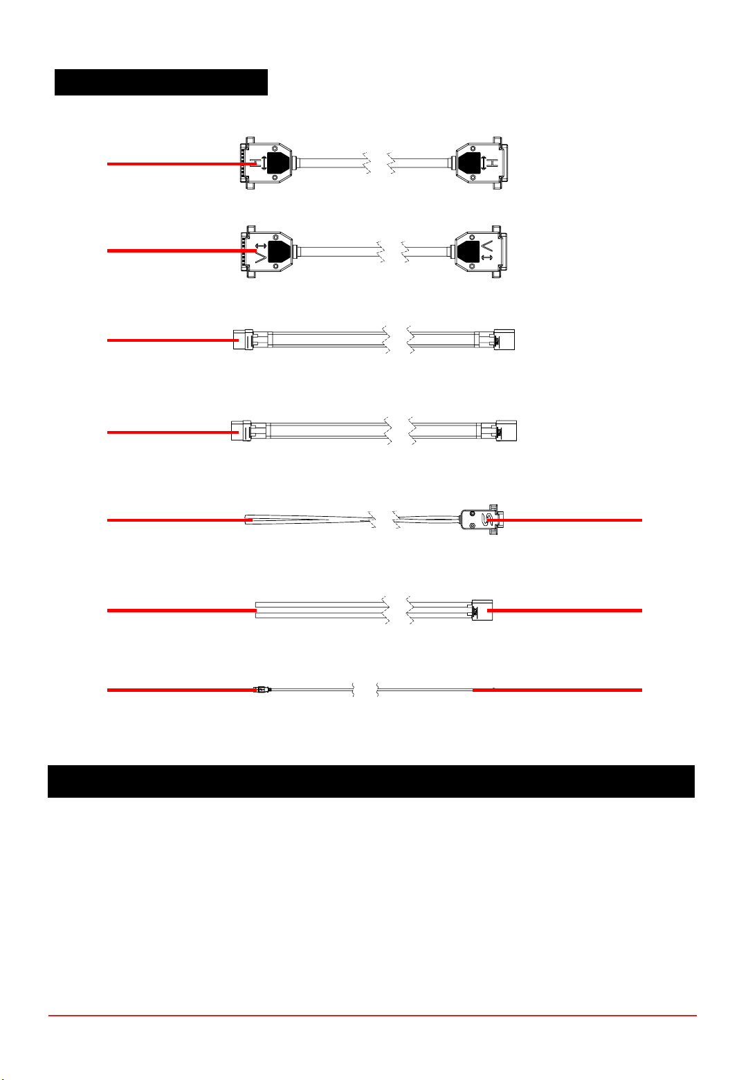
Figure 1.3.1 Accessories
ITEM DESCRIPTION
33. Power/Signal extension cable
(for HORIZONTAL configuration) 38. External power supply header
34.
Power/Signal extension cable
(for VERTICAL configuration)
* Not Applicable for Protium-2000
39. Free-end wires for user’s load
35. Stack power output (+ve) extension cable 40. Load connector (XT-90 male)
36. Stack power output (-ve) extension cable 41. USB connector to PC
37. Free-end wires for user’s power supply 42. Molex connector to telemetry port
33
34
35
36
40
37 38
41 42
39
1.3 STANDARD ACCESSORIES
CHAPTER 1 | OVERVIEW
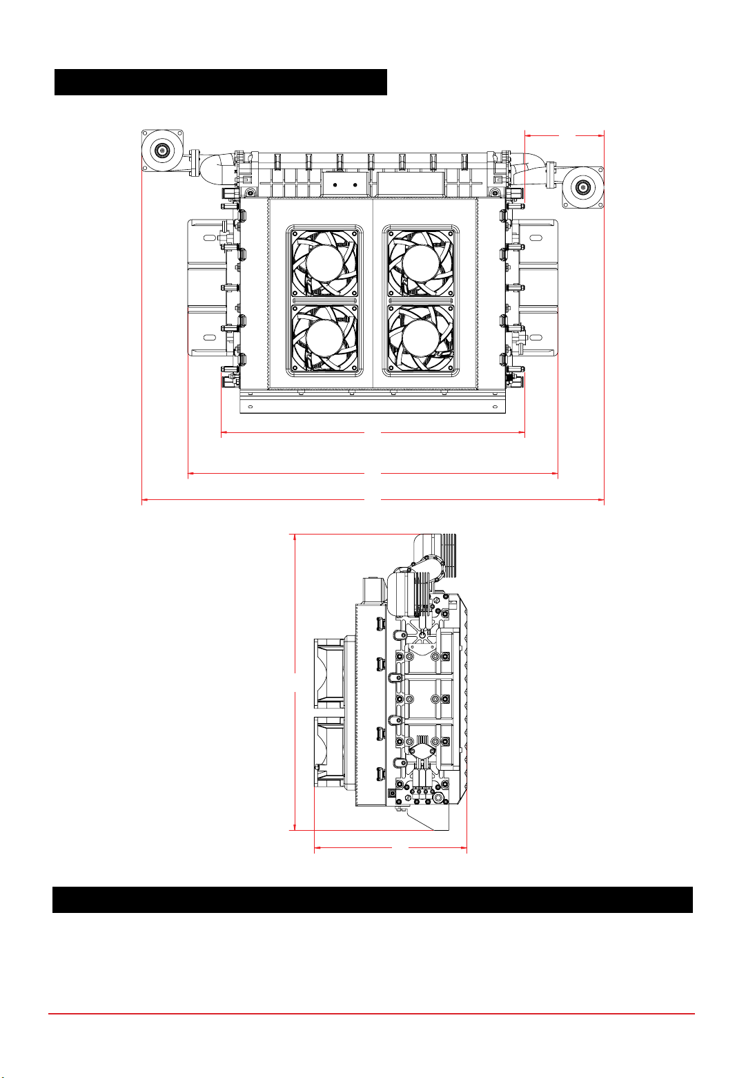
1.4 MECHANICAL DIMENSIONS –PROTIUM-2000
ALL DIMENSIONS IN MM
A94.50 D556.60
B365.40 E341.50
C445.60 F176.20
A
B
C
D
E
F

ALL DIMENSIONS IN MM
G163.40 L43.10
H145.00 M68.60
I131.40 N63.15
J113.00 O85.00
K3.20 (4x) P108.50
1.5 MECHANICAL DIMENSIONS –ELECTRIC CONTROLLER
G
H
K
J
I
L
M
N O P
CHAPTER 1 | OVERVIEW

1.6 MECHANICAL DIMENSIONS –STANDARD ACCESSORIES
ALL DIMENSIONS IN MM
Q1000.00 T1000.00
R1000.00
* Not Applicable for Protium-2000 U1000.00
S1000.00 V1800.00
T1000.00
Q
R
S
T
U
V
W
CHAPTER 1 | OVERVIEW
PROTIUM-2000 cannot be mounted in any orientation due to internal routings of the gas streams within the
fuel cell stack. The stack should also be level to ensure water does not get trapped in the Cathode channels,
obstructing the oxidant flow and causing potential performance drop and cell damage. Mount PROTIUM-2000
horizontally in the recommended orientation above, with the protective mask facing downwards and the cooling
fans facing upwards.
For optimal oxidant and cooling airflows, it is also recommended that there is at least 15cm unobstructed
clearance from the protective mask and oxidant blower inlet, and 30cm unobstructed clearance from the
cooling fans’ outlet.
Figure 1.7.1 Recommended orientation of PROTIUM-2000
1.7 MOUNTING AND AIR CLEARANCE
CHAPTER 1 | OVERVIEW

D
ALL DIMENSIONS IN MM
A8.00 C120
BR3.25 D392.80 (Centre to Centre)
1.8 MECHANICAL DIMENSION –MOUNTING AND CLEARANCE
Figure 1.8.1 Dimensions of the mounting holes
B
A
C
CHAPTER 1 | OVERVIEW

Fuel cell PROTIUM-2000
Type PEM
No. of cells 60
Architecture Closed cathode
Coolant Air cooled
Rated/gross power 2000/2400W
Rated/gross current 55.5/66.6A
Voltage output 36-54VDC
Start-up time 30s
Operating ambient temp. [-10,45]oC
Operating altitude without power derating 1500m AGL
System weight 7,690g
Max dimension 557 x 342 x 176mm
Fuel supply
Hydrogen gas Dry, 99.999% purity
Delivery pressure 0.7bar (10 psig)
Fuel consumption @ rated power 25L/min
Gas tubing PU, 8 x 5.5
Supply & purge control Solenoid valves with integrated pressure sensor
Stack leakage checks Automated via integrated pressure sensors
Electronic controller
Processor board FEATHER V1.2
Weight (including casing) 810g
Output connector XT-90
Warning & protections Low voltage, high/low temperature, high/low
pressure, low battery, stack leakage
Communication UART
Data acquisition (DAQ) software PC GUI app
Remote control Fan speed, blower speed, manual purge,
remote on-off
2SPECIFICATIONS
2.1 PROTIUM-2000 TECHNICAL DATA SHEET
CHAPTER 2 | SPECIFICATIONS
0
500
1000
1500
2000
2500
0.0
10.0
20.0
30.0
40.0
50.0
60.0
0.0 10.0 20.0 30.0 40.0 50.0 60.0 70.0
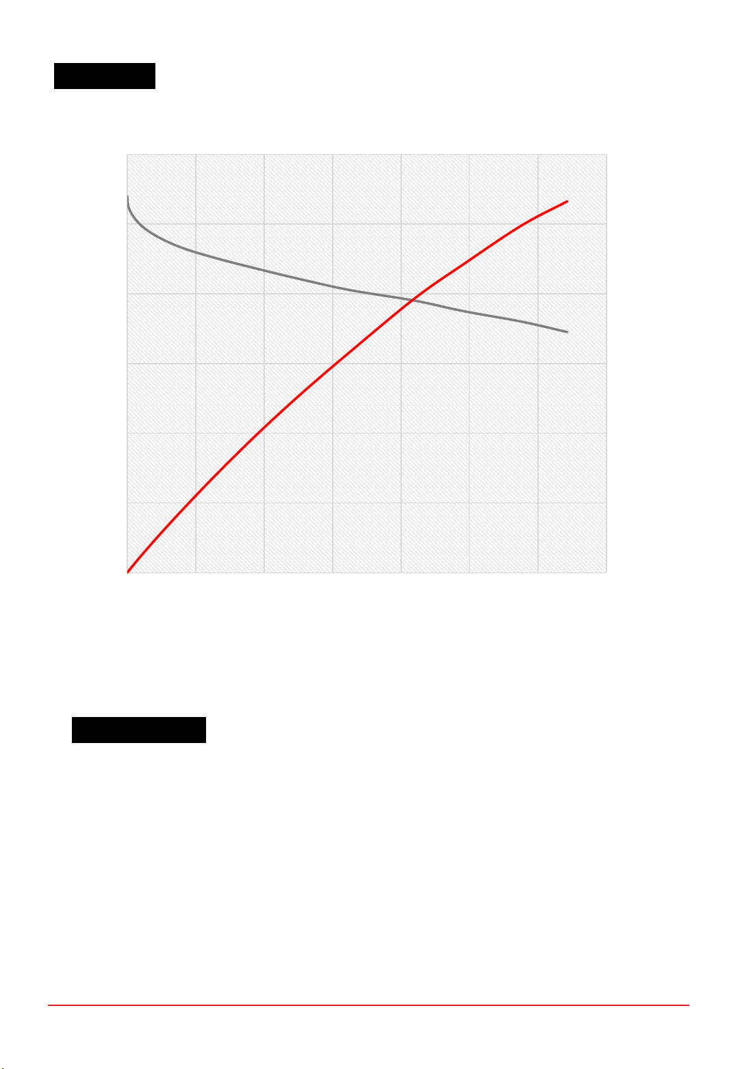
Power (W)
Voltage (V)
Current (A)
Figure 2.2.1 Nominal polarization curve for a fully conditioned PROTIUM-2000 at its Beginning-of-Life (BOL).
•Ambient temperature: 24oC
•Relative humidity: 60%
•H2supply pressure: 10psig
•Dead-ended operation
•Balance-of-plant (BOP) powered by fuel cell
•Tcell at 2000W: 66oC
2.2 VI CURVE
TEST CONDITIONS
CHAPTER 2 | SPECIFICATIONS
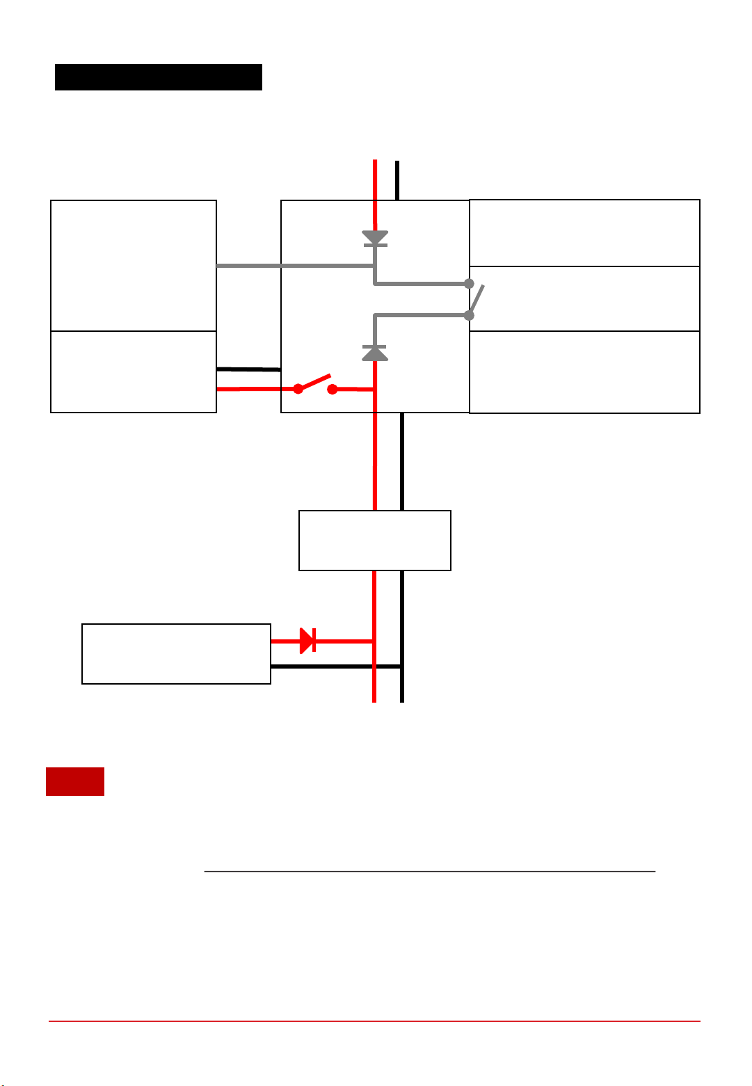
2.3 SYSTEM BLOCK DIAGRAM
1. An external power supply is required to initially turn on the electronic controller.
2. By default, the BOP Switch is set to 1. When the system enters “Running Phase” the fuel cell will be able
to power its own BOP, if Fuel cell power OUT voltage is higher than External Power Supply voltage. Tip:
use 15-36V External Power Supply to ensure that it is always lower than the Fuel cell power OUT voltage.
3. By setting the BOP Switch to 0, the External Power Supply will power the BOP at all times including
“Running Phase”.
Fuel cell
power IN
Power output
to LOAD
User Interface
•ON/OFF push button
•Status LED & Buzzer
Communication
•USB or
•Radio telemetry transmitter
External Power Supply
(15 to 90V, 300W)
Fuel cell
power OUT
36-54V
Hybrid Output Source
(optional)
DC-DC converter
(optional)
NOTE
PROTIUM-2000
fuel cell stack
Balance of Plant (BOP)
•Cooling System
•Oxidant System
•Valves
•Sensors
•Communications BOP Switch 1/0
Electronic
Controller
CHAPTER 2 | SPECIFICATIONS

1. Mount PROTIUM-2000 securely in the recommended orientation. Ensure that there is nothing blocking
the cooling air inlet below the protective mask (6),and sufficient unobstructed clearance from the
oxidant blower (1) inlets and cooling fans (5) outlet.
2. There are two Hydrogen gas purge tubing left and right of the fuel cell stack.Ensure that they are
securely connected to the H2 gas outlet connectors (11)and (16). Caution:channel the purge
tubing far away from the oxidant blower (1) inlets.
3. Connect PROTIUM-2000 to the Electronic Controller using the Power/Signal (33),Stack power
output (+ve) (35)and Stack power output (-ve) (36)extension cables.
4. Connect the Load connectors (30 and 40)and the Free-end wires (39)to your load.Tip:check
that the polarity is correct.It is also advisable to put an ON/OFF switch at your load and
ensure that it is turned OFF at this time.
5. Connect an external power supply (15-90V, 300W) to the external power supply receptacle (32)
using the supplied external power supply cable (37 and 38). Make sure that the external power
supply is OFF at this stage.
6. PROTIUM-2000 has two H2 gas inlet connectors (10 and 15). Connect your Hydrogen gas supply
to both inlets.Make sure that your Hydrogen gas supply is OFF at this stage.Caution:ensure that the
gas is regulated to 0.5-0.7bar gauge.
Reminder:ensure that all gas tubing and electrical wire connections are firm and secure.
The setup is now completed and PROTIUM-2000 is ready to be turned on.
3OPERATING PROCEDURES
3.1 SETTING UP PROTIUM-2000
CHAPTER 3 | OPERATING PROCEDURES
1. Connect the Molex connector (42)to the Telemetry transmitter port (31)and the USB
connector (41)to a PC.Launch the Spectronik Data Acquisition Graphic User Interface (DAQ GUI)
software. Choose the Com Port, set the Baud Rate (57600)and click the S logo.Tip:the latest DAQ
GUI software and user manual can be downloaded from the PROTIUM-2000 product
webpage.You can also use any serial data application like Hyperterminal.Set the
parameters (57600 baud rate, 8data bit, No parity, 1stop bit).If you wish to use your
own telemetry transmitter, follow the part number and pin-out diagram in Figure 3.2.1.
2. Turn on your external power supply and wait for 5s. A welcome message should appear in the GUI.
Status LED (28)will blink at 10%.
3. Click START.Alternatively, press and hold the On/Off push button (27)for more than 2s. PROTIUM-
2000 will enter its “Starting Phase” and the message <Low H2 supply> should appear.
4. Turn on your H2 gas supply.Caution:ensure that the gas pressure is regulated to 0.5-0.7bar
gauge.Insufficient delivery pressure may cause cell flooding and drop in performance, while
excessive pressure may rupture the fuel cell membrane, causing dangerous gas leakage
and irreversible cell damage.Ensure that your pressure regulator can provide Hydrogen
gas flow rate of more than 30L/min.
5. PROTIUM-2000 will do aseries of gas purging and internal diagnostic checks.The cooling fans and
oxidant blowers will turn on. If everything is normal, the system will enter its “Running Phase” –indicated
by the message in the GUI and asolid white Status LED.All system parameter values can now be seen in
the GUI.
6. Set the BOP Switch (29)to 0 or 1 as explained in Section 2.3.
PROTIUM-2000 is now ready to power your application.
3.2 TURNING ON PROTIUM-2000
CHAPTER 3 | OPERATING PROCEDURES
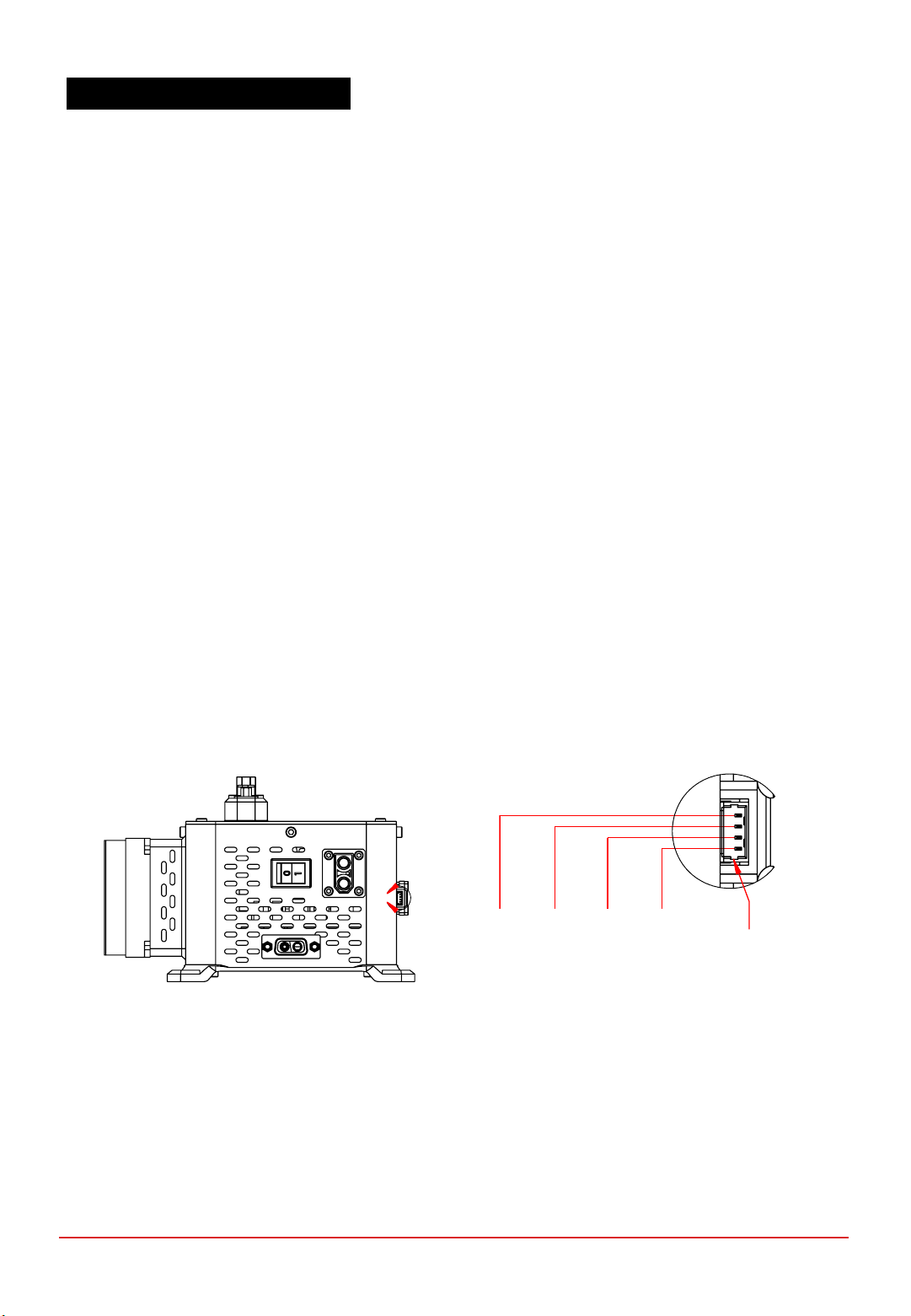
Figure 3.2.1 Telemetry transmitter port pin-out
B
Mfr. No: 53047-0410
Designed for Use with
51021-0400
Pin 1:
+5Vin
Detail B -Scale 2:1
Pin 2:
Ground
Pin 3:
TX
Pin 4:
RX

1. Turn ON your load and draw power as per normal. Caution: never pull the fuel cell voltage below 36V or
draw power beyond 2000W.
If hybrid battery is connected at the load, PROTIUM-2000 will provide up to its maximum rated output and
the rest is augmented by the battery. The total power available depends on the capacity of the battery. If no
hybrid battery is connected at the load, the following guideline is recommended:
3.3 POWERING YOUR LOAD WITH PROTIUM-2000
Mode Range Ramp-rate
Constant Voltage Load Open circuit voltage to 36VDC min or 2000W max -1VDC/second
Constant Current Load 0A to 55A or 2000W max +2A/second
Constant Power Load 0W to 2000W max +100W/second
2. During Running Phase, the following live status of the fuel cell can be monitored from the GUI.
Parameters Description
FCV FC voltage (V)
FCA FC current (A)
FCW FC power (W)
Energy Energy delivered by the fuel cell during this operation (Wh)
FCT1 FC temperature at location 1 (˚C)
FCT2 FC temperature at location 2 (˚C)
FAN Cooling fan duty cycle (%)
BLW Oxidant blower duty cycle (%)
H2P1 H2supply pressure (Barg)
H2P2 H2pressure in FC (Barg)
Tank-P* Gas tank pressure (Barg)
Tank-T* Gas tank temperature (˚C)
DCDCV* Converter voltage (V)
DCDCA* Converter current (A)
DCDCW* Converter power (W)
BattV External power supply voltage (V)
*with purchase of optional Spectronik accessories (gas tank, pressure regulator and DC/DC converter)
3. During Running Phase, you may manually control PROTIUM-2000 by clicking commands in the GUI such as
Purge, increasing/decreasing oxidant blower speed and cooling fans speed.Caution:manual control is
recommended for advanced users only.For optimal performance, remember to reset to AUTO
controls.
4. During operation, it is normal to see water coming out of the Cathode outlet duct (7) and purge tubing.
Ensure that water does not drip to any electrical components. Caution:there might be unreacted
Hydrogen gas coming out of the purge tubing.Keep away from fire and electric spark.Ensure
sufficient ventilation.
CHAPTER 3 | OPERATING PROCEDURES

1. Turn OFF your load. The cooling fans will turn faster to cool down the fuel cell, before returning to their
minimum speed.
2. In the GUI, click END.Alternatively, press and hold the On/Off push button for more than 2s. The
message <Shutdown Initiated> will appear in the GUI and PROTIUM-2000 will enter its “Shutdown Phase”
by carrying out aseries of shutdown procedures such as turning off the gas supply valves, cooling fans and
oxidant blowers.
3. The message <System OFF> will appear in the GUI.PROTIUM-2000 is now turned off. Status LED will
blink at 60% on standby awaiting the next start-up command.
4. If you do not intend to restart the system soon, turn OFF your Hydrogen gas supply and remove the
Hydrogen gas tubing from the H2 gas inlet connectors.Caution:some remaining gas in the
tubing will be released into the atmosphere.
5. Turn OFF the external power supply.All the cables can now be disconnected.
PROTIUM-2000 is now ready to be kept for storage.
3.4 SHUTTING DOWN PROTIUM-2000
CHAPTER 3 | OPERATING PROCEDURES

PROTIUM-2000 comes with in-built firmware control that is optimized to bring out its best performance over
the applicable ambient environment range.In normal use-case scenario, there is no need for user to fine-tune
the parameters. For advanced user who wishes to control the fuel cell manually, the following commands can
be entered via Hyperterminal or the GUI’s keyboard function:
Command PROTIUM-2000 action
start <enter> Starts the system
end <enter> Enters normal shutdown phase
ver <enter> Displays the firmware version
f <enter> Return to automatic cooling fan control
b <enter> Return to automatic oxidant blower control
p <enter> Open the Hydrogen purge valve for 2s. This is useful to remove excess water if
cell flooding is suspected due to decreasing power output.
= (equal) Increase cooling fan speed by 5% (manual control)
-(hyphen) Decrease cooling fan speed by 5% (manual control)
0Increase cooling fan speed by 1% (manual control)
9Decrease cooling fan speed by 1% (manual control)
]Increase oxidant blower speed by 3% (manual control)
[Decrease oxidant blower speed by 3% (manual control)
PROTIUM-2000 has several in-built protections. The LED will flash and error message will appear in the GUI.
Follow the basic troubleshooting guide below.Most errors should be rectified once the suggested corrective
action has been done and the system restarted.
If the error persists, contact support@spectronik.com.
Tip:you may also long press the ON/OFF push button by >2s to turn ON/OFF the system instead of
entering “start” and “end” command via the GUI.
SYSTEM MONITORING, PROTECTIONS &
MANUAL CONTROL
4
4.1 MANUALLY CONTROLLING THE PROTIUM-2000
4.2 SYSTEM WARNING &PROTECTIONS
CHAPTER 4 | SYSTEM MONITORING & PROTECTIONS
Table of contents
Other Spectronik Industrial Equipment manuals


