manuals.online logo
Brands
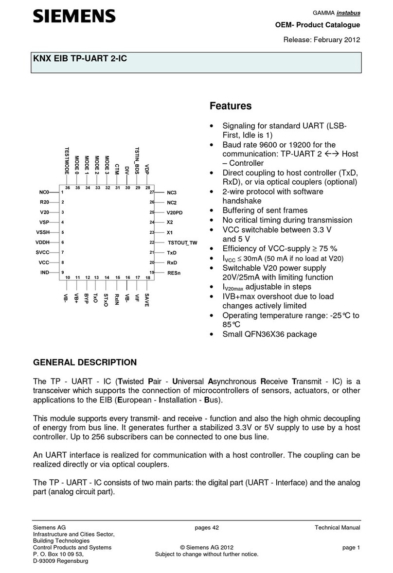
  1. Home
  2. •
  3. Brands
  4. •
  5. Siemens
  6. •
  7. Industrial Equipment
  8. •
  9. Siemens Simatic PROFIsafe User manual

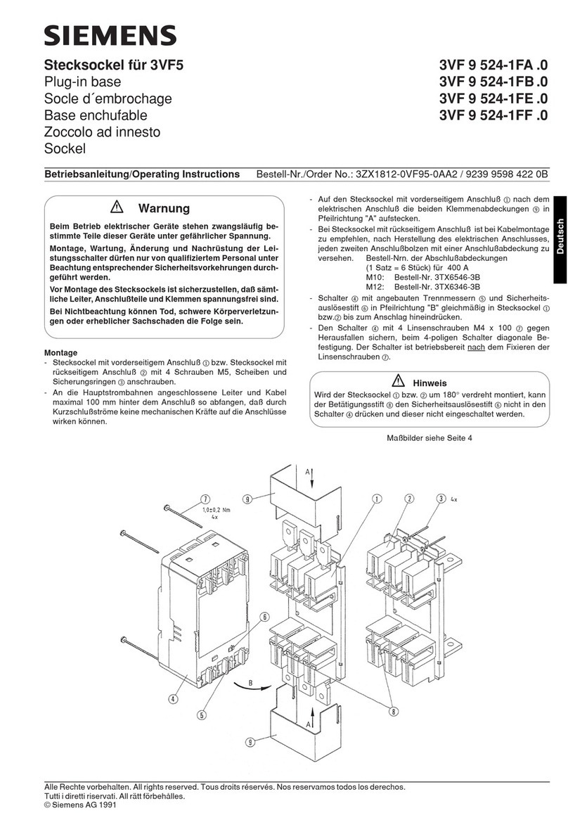
Siemens Simatic PROFIsafe User manual

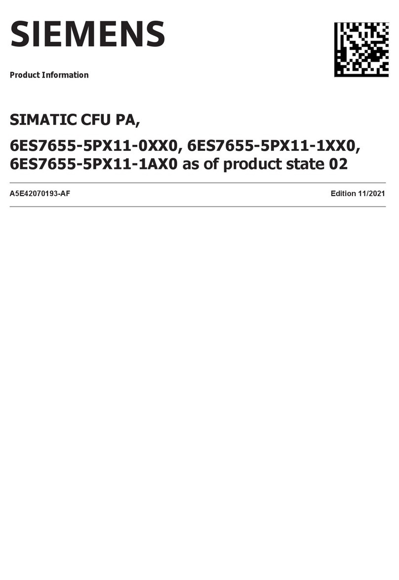
SIMATIC
Extension Units PROFIsafe
Quick Install Guide
Vorbereitungen
Preparations
A5E40503758, 11/2019
1.2 Lieferumfang – Scope of delivery
Bedienelemente einbauen
Installing operator controls
2
One Extension Unit, one power supply connector, and four screws M4x20 for fixation at the PRO
device are contained in the scope of delivery.
Im Lieferumfang sind eine Extension Unit, eine Stromversorgungsklemme und vier Schrauben
M4x20 zur Befestigung am PRO-Gerät enthalten.
1.3 Bedienelemente – Operator controls
You will find the following and additional operating elements for the Extension Unit on the internet
(https://mall.industry.siemens.com/mall/en/WW/Catalog/Products/10046164).
Die folgenden und weitere Bedienelemente für die Extension Unit finden Sie im Internet
(https://mall.industry.siemens.com/mall/de/WW/Catalog/Products/10046164).
Leuchtdrucktaster
Illuminated pushbutton
Leuchtmelder
Signal lamp
Wahlschalter
Selector switch
Schlüsselschalter
Key switch
NOT-HALT-Pilzdrucktaster
EMERGENCY STOP
Mushroom Pushbutton
6AV7674-1MB00-0AA0
6AV7674-1MC00-0AA0
6AV7674-1MD00-0AA0
6AV7674-1ME00-0AA0
6AV7674-1MA00-0AA0
Abb. / Fig. Bedienelement / Operator control MLFB
1.4 Einbauplätze auswählen – Selecting the mounting positions
2.1 Bedienelemente einbauen – Mounting operator controls
2.2
2.1 Extension Unit auseinanderbauen – Disassembling the Extension Unit
Typ / Type
Standard-Bedienelement
NOT-Halt-Taster
Standard operator control
EMERGENCY Stop button
Standard-Bedienelement
Standard operator control
Standard-Bedienelement
Standard operator control
Standard-Bedienelement
Standard operator control
Vorderseite / Front
112211310495867
2
V14:
≥V15: 133124115106978
Oben / Top
Rückseite / Rear
12 111 210 3948576
13 212 311 410 59687
Beachten Sie, dass sich die Nummerierung der Einbauplätze umkehrt, wenn man die Extension
Unit von der Rückseite betrachtet.
Note that the numbering of the slots is reversed when you view the Extension Unit from the rear.
2
Oben / Top
Größe 4
Size 4
3
5
1.2 Nm
6
7
0.5 Nm
Nur das Lesegerät 6GT2831‑6AA50 verwenden! - Use 6GT2831‑6AA50 Reader only!
6GT2831‑6AA50
USB
4
Es können maximal 2 NOT-Halt-Taster eingebaut werden
A maximum of 2 emergency stop buttons can be installed.
1
2
1
3
4
T10
T20
T20
T20
Wenn Sie nur einen NOT-Halt-Taster einbauen, dann ist für diesen NOT-Halt-Taster der 5-polige
Stecker "rechts" zu verwenden, gekennzeichnet mit rotem Klebeband.
When installing only one emergency stop button, use the 5 pin connector "right" marked with red
adhesive tape.
Die folgenden Abbildungen zeigen die Zuordnung der Einbauplätze von Vorderseite zu Rückseite
am Beispiel der Extension Unit 22“.
The following figures show the assignment of the mounting positions of front and rear side using the
example of the Extension Unit 22“.
Die Einbauplätze sind analog zur Darstellung im TIA Portal in aufsteigender Reihenfolge von links
nach rechts nummeriert.
The slots are numbered the same way as they are shown in TIA Portal, in ascending order from
left to right.
1
6AV7674‑1MG00‑0AA0
TIA
TIA
V14:
≥V15:
TIA
TIA
Vor Einbau und Inbetriebnahme – Before mounting and commissioning
1.1
WICHTIG: Beachten Sie alle dem Gerät beiliegenden Dokumente und die Betriebsanleitung, bevor
Sie Bedienelemente einbauen und die Extension Unit installieren. Die vollständige Dokumentation des
Geräts finden Sie im Internet (https://support.industry.siemens.com/cs/ww/de/view/109742323).
IMPORTANT: observe all documents enclosed with the device and the operating instructions manual
before mounting operator controls and installing the Extension Unit. You find the complete documen-
tation of the device on the internet (https://support.industry.siemens.com/cs/ww/en/view/109742323).
Das Handbuchsymbol weist auf detaillierte Informationen in der Betriebsanleitung hin.
The manual symbol refers to detailed information in the operating instructions.
Die Extension Unit ist für 16:9 PRO-Geräte für Standfuß (erweiterbar, Flansch unten) und für Tragarm
(erweiterbar, Rundrohr) konzipiert.
The Extension Unit is designed for 16:9 PRO devices for pedestal (extendable, flange bottom) and for
support arm (extendable, round tube).
Weitere Elemente
Additional elements
Lesegerät einbauen – Mounting a reader device
3
Standard operator control
Standard-Bedienlement
EMERGENCY Stop button
NOT-Halt-Taster
4
5
5
6
1.2 Nm
Oben / Top
2
1
Größe 4
Size 4
6-pin
5-pin
0.8 Nm
T10
C
M
Y
CM
MY
CY
CMY
K
hmi_extension_unit_ps_quick_install_guide_page_1.eps 1 12.11.2019 10:04:48hmi_extension_unit_ps_quick_install_guide_page_1.eps 1 12.11.2019 10:04:48
Haftungsausschluss
Wir haben den Inhalt der Druckschrift auf Übereinstimmung mit der beschriebenen Hard- und
Software geprüft. Dennoch können Abweichungen nicht ausgeschlossen werden, so dass wir für
die vollständige Übereinstimmung keine Gewähr übernehmen. Die Angaben in dieser Druckschrift
werden regelmäßig überprüft, notwendige Korrekturen sind in den nachfolgenden Auflagen
enthalten.
Abbildungen
Das vorliegende Dokument enthält Abbildungen zu den beschriebenen Geräten und Zubehör.
Die Abbildungen können bezogen auf das gelieferte Gerät und Zubehör in Einzelheiten abweichen.
Illustrations
This document contains illustrations of the described devices and accessories.
The illustrations may deviate from the particularities of the delivered device and accessories.
Technische Support-Zentrale
Central Technical Support
https://support.industry.siemens.com
Reparatur und Ersatzteile
Service and spare parts
https://support.industry.siemens.com/sc/de/en/sc
© Siemens AG 2019. All rights reserved
A5E40503758-AD, 11/2019
Disclaimer of Liability
We have reviewed the contents of this publication to ensure consistency with the hardware and
software described. Since variance cannot be precluded entirely, we cannot guarantee full
consistency. However, the information in this publication is reviewed regularly and any necessary
corrections are included in subsequent editions.
Siemens AG
Digital Industries
Postfach 48 48
90026 NÜRNBERG
3.1 Front zusammenbauen – Mounting the front
1
2
2
X17
Vorderseite / Front side
Rückseite / Rear side
X15
Rückseite / Rear side
1
Unterer Deckel aus dem Lieferumfang des PRO-Geräts
Lower cover from the scope of delivery of the PRO device
S1
SIMATIC PRO-Gerät / SIMATIC PRO device
1
4 x T10,
0.8 Nm
4 x T20,
2.5 Nm
3.3 Front anbauen und anschließen – Mounting and connecting the front
4 x T20,
1.5 Nm
3.2 Standfuß- oder Tragarmmontage – Pedestal or support arm mounting
Standfußmontage / pedestal mounting
Tragarmmontage / support arm mounting
4 x T20,
2.5 Nm
4 x T20,
1.5 Nm
2
3.2 PRO-Gerät und Kommunikationsmodul – PRO device and communication module
6
2 x T20,
1.5 Nm
Rückseite / Rear side
4 x T20,
1.5 Nm
Extension Unit anbauen
Mounting the Extension Unit
3
Extension Unit anschließen
Connecting the Extension Unit
4
3
4
Beispiel: Adresse „383“ / Example: Address „383“
PROFIsafe-Adresse einstellen / Setting the PROFIsafe address
Switch AddressWeightingBit number
ON
1110
2221
3442
4883
516164
632325
764646
801287
92562568
10 05129
383
OFF
0.25 ... 2.5 mm2
+
–
2
2.5 ... 4 mm2
T20,
1.5 Nm
Bedienelemente projektieren / Configuring operator controls
Verdrahten Sie die Standard- und Safety-Bedienelemente über die Projektierung im
TIA Portal.
Die Schaltstellungen der Bedienelemente und die Beschreibung der zugehörigen
Eingangsbits finden Sie in der Betriebsanleitung.
Wire the Standard and Safety operator controls via configuration in the TIA Portal.
You will find the operator controls‘ switching settings and the description of the
corresponding input bits in the operating instructions.
C
M
Y
CM
MY
CY
CMY
K
hmi_extension_unit_ps_quick_install_guide_page_2.eps 1 12.11.2019 10:09:39hmi_extension_unit_ps_quick_install_guide_page_2.eps 1 12.11.2019 10:09:39

Other Siemens Industrial Equipment manuals

Siemens Vendor User manual

Siemens

Siemens Vendor User manual

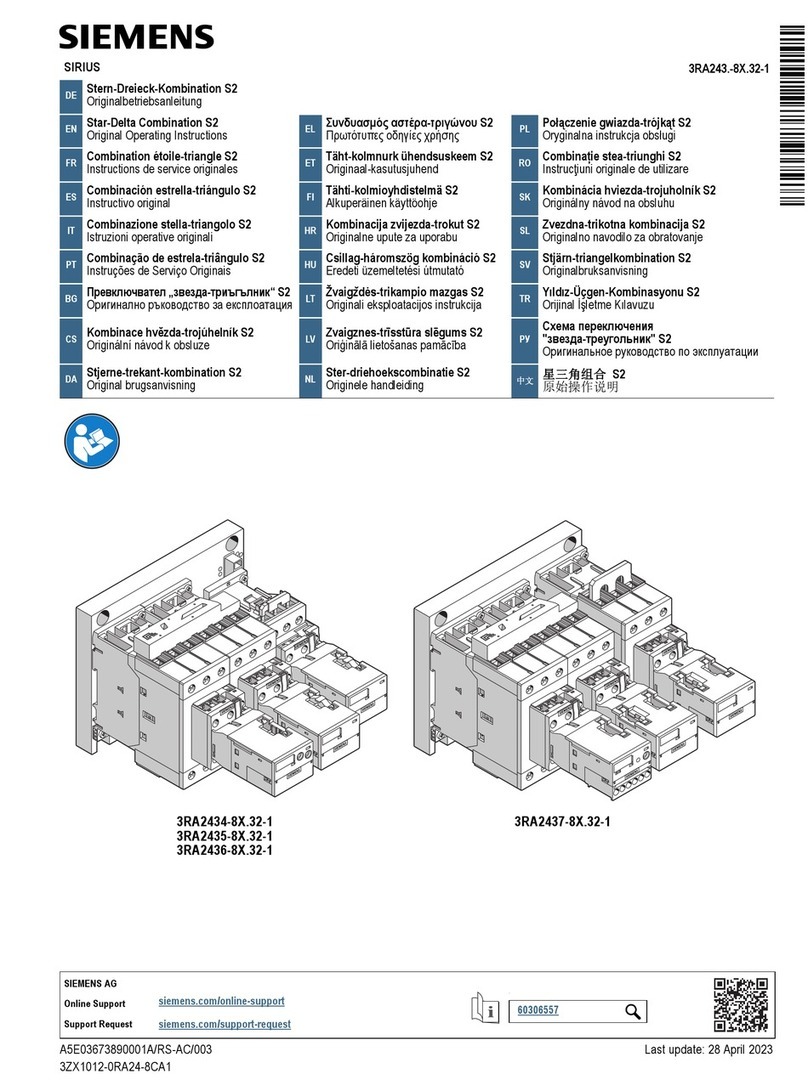
Siemens SITRANS FC300 DN 4 User manual

Siemens

Siemens SITRANS FC300 DN 4 User manual

Siemens SINUMERIK MPP 1500D Technical Document

Siemens

Siemens SINUMERIK MPP 1500D Technical Document

Siemens SIPROCESS GA700 User manual

Siemens

Siemens SIPROCESS GA700 User manual

Siemens 3WN6 User manual

Siemens

Siemens 3WN6 User manual

Siemens 3VA9 1-0WD 0 Series User manual

Siemens

Siemens 3VA9 1-0WD 0 Series User manual

Siemens 7VE51 User manual

Siemens

Siemens 7VE51 User manual

Siemens SINUMERIK 840D sl TCU 30.3 Technical Document

Siemens

Siemens SINUMERIK 840D sl TCU 30.3 Technical Document

Siemens 3VL9300-3M.00 User manual

Siemens

Siemens 3VL9300-3M.00 User manual

Siemens ET 200MP User manual

Siemens

Siemens ET 200MP User manual

Siemens LITHOSTAR Multiline SP Installation manual

Siemens

Siemens LITHOSTAR Multiline SP Installation manual

Siemens RUGGEDCOM WIN5151-V-GPS User manual

Siemens

Siemens RUGGEDCOM WIN5151-V-GPS User manual

Siemens 3VA9110-0WC00 User manual

Siemens

Siemens 3VA9110-0WC00 User manual

Siemens 3VT9100-1U.00 User manual

Siemens

Siemens 3VT9100-1U.00 User manual

Siemens MICROMASTER 440 User manual

Siemens

Siemens MICROMASTER 440 User manual

Siemens Worm Gearbox S 5 BA 2012 User manual

Siemens

Siemens Worm Gearbox S 5 BA 2012 User manual

Siemens Climatix ECO User manual

Siemens

Siemens Climatix ECO User manual

Siemens ULTRAMAT 6F User manual

Siemens

Siemens ULTRAMAT 6F User manual

Siemens SIRIUS 3RA242.-8X.3.-1 User manual

Siemens

Siemens SIRIUS 3RA242.-8X.3.-1 User manual

Siemens SINUMERIK ONE NCU 1760 Technical Document

Siemens

Siemens SINUMERIK ONE NCU 1760 Technical Document

Siemens 5WG1 260-4AB23 Service manual

Siemens

Siemens 5WG1 260-4AB23 Service manual

Siemens SIMATIC NET User manual

Siemens

Siemens SIMATIC NET User manual

Siemens SIMATIC NET User manual

Siemens

Siemens SIMATIC NET User manual

Siemens 3VW9011-0AN73 User manual

Siemens

Siemens 3VW9011-0AN73 User manual

Popular Industrial Equipment manuals by other brands

Alipa CODIPRO QLR instruction manual

Alipa

Alipa CODIPRO QLR instruction manual

ABB HT580927 Operation manual

ABB

ABB HT580927 Operation manual

GSi VersaLoop 8 owner's manual

GSi

GSi VersaLoop 8 owner's manual

YOKOGAWA PR20 user manual

YOKOGAWA

YOKOGAWA PR20 user manual

Riello FCU 09 N manual

Riello

Riello FCU 09 N manual

BIRD TERMALINE 8400 SERIES Instruction book

BIRD

BIRD TERMALINE 8400 SERIES Instruction book

Casa W3 xs Smart Disassembly instructions

Casa

Casa W3 xs Smart Disassembly instructions

Tisch Environmental TE-5000D Operation manual

Tisch Environmental

Tisch Environmental TE-5000D Operation manual

Rockwell Automation Allen-Bradley MagneMotion QuickStick Series Design guide

Rockwell Automation

Rockwell Automation Allen-Bradley MagneMotion QuickStick Series Design guide

MyBinding SealerSales KF-772DH instruction manual

MyBinding

MyBinding SealerSales KF-772DH instruction manual

Danfoss VLT Safety Option MCB 150 installation guide

Danfoss

Danfoss VLT Safety Option MCB 150 installation guide

Balluff BTL PF 400 C15A Series user guide

Balluff

Balluff BTL PF 400 C15A Series user guide

Frimax MAXON Ocultas TE-20 Series Manual de usuario

Frimax

Frimax MAXON Ocultas TE-20 Series Manual de usuario

ASA Electronics DA VINCI ST Original instructions

ASA Electronics

ASA Electronics DA VINCI ST Original instructions

Crafco SUPER SHOT 60 parts manual

Crafco

Crafco SUPER SHOT 60 parts manual

Schleuniger Uni-M 1516 quick start guide

Schleuniger

Schleuniger Uni-M 1516 quick start guide

Grundfos MQ instructions

Grundfos

Grundfos MQ instructions

ABB HT613072 Operation manual

ABB

ABB HT613072 Operation manual

manuals.online logo
manuals.online logoBrands
  • About & Mission
  • Contact us
  • Privacy Policy
  • Terms and Conditions

Copyright 2025 Manuals.Online. All Rights Reserved.