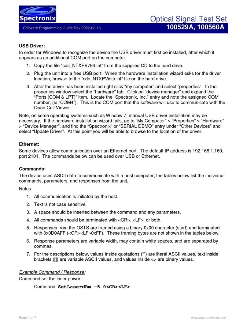
Spectronix 100529A User manual

Optical Signal Test Set
User’s Manual 2023-02-17
100529A. 100560A
Page 1 of 6 www.spectronixinc.com
Description:
The Optical Signal Test Set (OSTS) is a low power miniature instrument intended for general purpose
optical testing. The 100529A consists of a high performance optical power meter, stable CW laser
source, and variable optical attenuator. All functions are controlled and monitored via Windows
software and a USB port which also provides power to the unit.
Optical System Test Set, PN 100529A
An OEM CCA version of the OSTS is also offered (PN 100560A). The OEM version adds a second
optical power meter and Ethernet port which can be used instead of the USB.
Optical System Test Set Dual OEM version, PN 100560A
Operation:
All optical connections are brought out on single mode LC connectors allowing each subsystem to be
used independently or together. Connecting the laser output, variable attenuator, and power meter
together allows for self calibration. The supplied Windows software allows the user to read and log
optical power levels, adjusts the laser power, and set the VOA attenuation, as well as some advanced
features described below.

Optical Signal Test Set
User’s Manual 2023-02-17
100529A. 100560A
Page 2 of 6 www.spectronixinc.com
Connection
In order for the unit to communicate via USB, some operating systems require a driver to be installed;
see the USB driver section at the end of this document. Upon startup the application will search for
OSTS devices connected via USB and display them in the dropdown list next to the button with the
USB icon. Selecting a device and pressing the USB connect button will allow the device to
communicate with the host computer over the USB port.
The Dual OEM version also features an Ethernet port. Entering the device’s IP address in the “IP
Address” box and pressing the “Connect” button will allow the device to communicate with the host
computer via the Ethernet port. For discovering and managing network settings see the Ethernet
section at the end of this document.
Operation
The power meter features a numeric read-out as well as a strip chart for displaying power readings.
Data can optionally be saved to a .CSV file for later analysis by clicking on the disk icon. The strip
chart can be taxing on computer resources and is dependent on the sample rate and data set size; if
performance issues are noticed, reducing these parameters can help. The 100529A provides an LED
next to the USB port which flashes blue at the sample rate; if the laser is on, the LED will flash
blue/red. Several controls on the main panel are used for manipulating the strip chart appearance
and are described below.
•Run toggle button: Enables / disables displaying new power readings on the strip chart.
•Clear button: Removes all data points from the strip chart.
•Disk icon: Saves all strip chart data to a user specified .CSV file.

Optical Signal Test Set
User’s Manual 2023-02-17
100529A. 100560A
Page 3 of 6 www.spectronixinc.com
•Auto toggle button: When enabled the chart auto-scales to the chart data; the chart
continues to expand accordingly as new data points are added.
•Zoom All button: Expands the chart to its extremes (-120dBm to +10dBm).
•Seconds spin box: Sets the X axis range of the strip chart. As samples older than the
specified range expire, they are automatically removed from the chart.
•Using the check boxes above power meter readings, averaged data and raw data can
optionally be displayed in the plot window.
In addition to using the controls above, the plot range can be controlled manually using the mouse.
To zoom in, hold the left mouse button and drag inside the plot area. While the chart is running, this
will adjust the Y axis only, when stopped both X and Y axis will be adjusted. To zoom out, simply
right-click anywhere in the chart area.
The laser power can be varied between 0 and -10dBm by adjusting the laser dial. When the dial has
focus the mouse wheel can be used to change the power by +/-3dB and the up/down keys by +/-1dB.
The button in the center of the dial displays the current power; toggling this button turns the laser
on/off. The laser settings are saved in the application and restored at start-up.
The VOA knob is used to set the attenuator loss. The knob can be varied between the calibrated
insertion loss and the VOA’s maximum useable range. When the dial has focus the mouse wheel and
up/down keys can be used to change the attenuation by +/-0.3dB, the page up/down keys by 1.0dB,
and the arrow keys by 0.1dB. The attenuation is saved in the application and restored at start-up.
Advanced Features
Several advanced features are exposed when the down arrow button is selected. The power meter
features an advanced digital filter implemented in hardware; different filter settings are can be
selected using the “Fast Sampling” checkbox. When this box is checked, the sample rate increases
to 50 samples per second but the filter’s effectiveness is decreased. In normal mode, the sample rate
is 10 samples per second. Additionally, the user can select a variable number of samples to average
for display and logging purposes (1 for no averaging). The averaged data is plotted with colored lines
and when the “Plot Raw Data” box is checked the un-averaged data is displayed in grey. Un-
checking the “Calibrated” box, will cause the application to ignore the calibration and display the un-
calibrated data.

Optical Signal Test Set
User’s Manual 2023-02-17
100529A. 100560A
Page 4 of 6 www.spectronixinc.com
Calibration and Zeroing
The Optical Signal Test Set is designed to be self calibrating using a few simple steps listed below.
Calibration is performed at the factory and all parameters are stored in the unit, therefore calibration
only needs to be performed periodically or if the measurement accuracy is in question. Each step is
dependent on the previous and should be executed in the order shown below. The calibration
controls are displayed in the correct order from left to right in the application. The optical components
are wavelength sensitive; therefore the calibration will only be accurate for the wavelength used
during calibration.
Calibrate OPM1/2
The power meters(s) are calibrated against a known power level
1. Connect a stable source of known power to the power meter 1/2 input.
2. Enter the known optical power level in the “Actual Cal Power” box.
3. Press the “Calibrate OPM1/2” button. The power meter should now read the same value
entered in the box.
Laser Zero
The laser is automatically adjusted for a maximum output power of 0dBm.
1. Connect the laser output to the OPM1 input using a 0dB loopback cable.
2. Execute the “Zero Laser” command from the advanced screen. This takes only several
seconds to complete.

Optical Signal Test Set
User’s Manual 2023-02-17
100529A. 100560A
Page 5 of 6 www.spectronixinc.com
Calibrate VOA
This procedure measures the minimum insertion loss and calibrates the VOA in 0.1dB steps. The
entire procedure takes less then ten minutes to complete. When finished the VOA dial will reflect the
minimum VOA insertion loss and maximum usable range. The laser must already be zeroed.
1. Connect the laser output to the VOA input and the VOA output to OPM1 using cables with
minimal loss.
2. Press the “Calibrate VOA” button on the advanced screen. A “Calibration” message and
status will appear on the screen during calibration. This can take up to 30 minutes to
complete.
Low Power OPM Calibration
The power meter exhibits very accurate law conformance to about -85dBm; below this level
calibration is used to correct errors in law conformance. During calibration the VOA attenuation is
automatically varied from minimum insertion loss through its useable range in 1dB steps. At each
step, the measured value along with the actual power level is recorded and stored. This table is then
used to correct all subsequent measurements within this power range. Calibration accuracy is
dependent on the accuracy of the VOA calibration.
1. Set the VOA for minimum loss.
2. Connect a stable optical source (laser output) to the VOA input and the VOA output to the
power meter input using external attenuators so that the power meter reads between -80 and -
75dBm. Due to the large amount of attenuation and the low power levels, it’s suggested to
split the attenuation equally between the four ports.
3. Due to the high sensitivity of the OPM, the OSTS and all optical connections should be placed
in a dark box or low ambient light environment to ensure stray light does not effect the
calibration.
4. Execute the “Calibrate OPM” command from the advanced screen. A “Calibration” message
and status will appear on the screen during calibration. Calibration typically takes about 60
seconds to complete. The OSTS should be power cycled after calibration.
An automated VOA sweep utility and calibration read function can be found under the factory controls
section by pressing the gear wheel when the advanced controls are exposed. These utilities can be
useful for characterizing performance and calibration.
Ethernet (Dual OEM version)
The dual OEM CCA comes supplied with a Lantronix XPort Pro Ethernet interface which can be used
for communication instead of the USB port. The device IP and MAC address can be read from the
USB port using the “Read IP” button. This command takes about 5 seconds to execute, after which
the XPort interface is automatically rebooted.
The IP address can be changed over USB or Ethernet by entering the desired IP address in the dialog
box under “IP Address” and pressing the “Set” button. This command takes about 10 seconds to
execute, after which the XPort interface is automatically rebooted. After reboot is complete (~15
seconds), the device should be power cycled for the changes to take effect.
Alternatively the XPort interface can be configured using the embedded web page. The default login
credentials are: user name: “admin”, password: “PASSWORD”. Care should be taken when
modifying settings other than the IP address.

Optical Signal Test Set
User’s Manual 2023-02-17
100529A. 100560A
Page 6 of 6 www.spectronixinc.com
Should the configuration options become corrupt the factory default configuration can be recovered by
executing the “Factory Reset XPort” button. The button can be found by first exposing the advanced
options screen (down button), then pressing the gear button. The factory default IP address is
192.168.1.160 port 2101. Alternatively the Lantronix provisioning manager can be used to discover
connected devices. Vendor documentation can be found at https://docs.lantronix.com/products/xport-
edge/ug/5.1/
USB Driver:
In order for some versions of Windows to recognize the device the USB driver must first be installed,
after which the unit appears as an additional COM port on the computer. Currently Windows XP,
Vista, and 7, 8, and 10 are supported.
1. Copy the file “cdc_NTXPV764.inf” from the supplied CD to the hard drive.
2. Plug the device into a free USB port. When the hardware installation wizard asks for the driver
location, browse to the “cdc_NTXPVista.inf” file on the hard drive.
3. After the driver has been installed right click “my computer” and select “properties”. In the
properties window select the “hardware” tab. Click on “device manager” and expand the
“Ports (COM & LPT)” item. Locate the “Spectronix, Inc.” entry and note the assigned COM
number, (ie “COM4”). This is the COM port that the software will use to communicate with the
device.
Note, on some operating systems such as Window 7, manual USB driver installation may be
necessary. If the hardware installation wizard fails, go to “My Computer” > “Properties” > “Hardware”
> “Device Manager”, and find the “Spectronix” or “SERIAL DEMO” entry under “Other Devices” and
select “Update Driver”. At this point you will be able to browse to the location of the driver.
Notes and Precautions
•The maximum input power on any port is +10dBm. Levels above this value may damage
the device.
•Due to the very low leakage of the photodetector, when powering up the device with little
or no power on the power meter port, the device may initially take several seconds to
register an accurate reading while the circuitry stabilizes. Applying a signal above -70dBm
will immediately stabilize the readings.
•Small amounts of light can leak through fiber jackets and into connectors and components
affecting power readings at very low power levels. Care should be taken to minimize
leakage by utilizing light shielding when possible.
•For the dual OEM CCA version, see data sheet for notes on shielding.
LOV and Clearing Procedure
The OSTS contains both volatile and nonvolatile memory. The application processor only stores
calibration data generated internally, therefore there is no clearing procedure for this.
The Lantronix XPort Edge used in the OEM version is capable of storing user files and network
configuration data. Executing the “Factory Reset XPort” command will reset the configuration back to
the factory default and will also format the XPort flash file system. Additional Information regarding
memory and formatting can be found on the Lantronix website.
This manual suits for next models
1
Table of contents
Other Spectronix Test Equipment manuals

