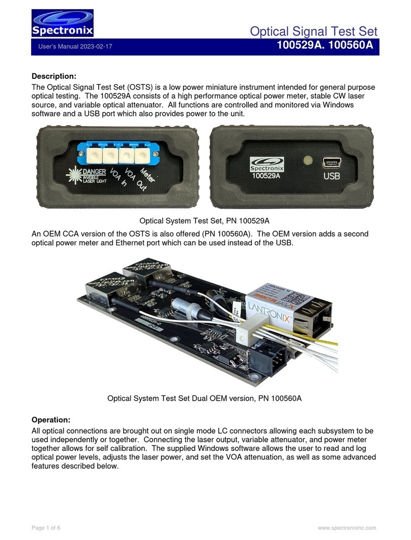
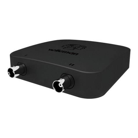
Spectronix 100529A User manual

Optical Signal Test Set
Software Programming Guide Rev 2022-02-16
100529A, 100560A
Page 1 of 7 www.spectronixinc.com
USB Driver:
In order for Windows to recognize the device the USB driver must first be installed, after which it
appears as an additional COM port on the computer.
1. Copy the file “cdc_NTXPV764.inf” from the supplied CD to the hard drive.
2. Plug the unit into a free USB port. When the hardware installation wizard asks for the driver
location, browse to the “cdc_NTXPVista.inf” file on the hard drive.
3. After the driver has been installed right click “my computer” and select “properties”. In the
properties window select the “hardware” tab. Click on “device manager” and expand the
“Ports (COM & LPT)” item. Locate the “Spectronix, Inc.” entry and note the assigned COM
number, (ie “COM4”). This is the COM port that the software will use to communicate with the
Quad Cell Viewer.
Note, on some operating systems such as Window 7, manual USB driver installation may be
necessary. If the hardware installation wizard fails, go to “My Computer” > “Properties” > “Hardware”
> “Device Manager”, and find the “Spectronix” or “SERIAL DEMO” entry under “Other Devices” and
select “Update Driver”. At this point you will be able to browse to the location of the driver.
Ethernet:
Some devices allow communication over an Ethernet port. The default IP address is 192.168.1.160,
port 2101. The commands below can be used over USB or Ethernet.
Commands:
The device uses ASCII data to communicate with a host computer; the tables below list the individual
commands, parameters, and responses from the unit.
Notes:
1. All communication is initiated by the host.
2. Text is not case sensitive.
3. A space should be inserted between the command and any parameters.
4. All commands should be terminated with <CR>, <LF>, or both.
5. Responses from the OSTS are framed using a binary 0x00 character (start) and terminated
with 0x0D0AFF (<CR><LF>0xFF). These framing bytes are not shown in the tables below.
6. Response parameters are variable width, may contain white spaces, and are separated by
commas.
7. For the descriptions below, values inside quotations (“”) are literal ASCII values, text inside
brackets ([]) are variable ASCII values, and values inside <> are binary values.
Example Command / Response:
Command set the laser power:
Command: SetLaserdBm -5 0<CR><LF>

Optical Signal Test Set
Software Programming Guide Rev 2022-02-16
100529A, 100560A
Page 2 of 7 www.spectronixinc.com
Commands
Get Unit Information
Command: Description:
“?”
Response: Description:
“?” Echo command
“100529A” or
“100560A”
Unit name (fixed)
[major.minor] Firmware version
Example:
Notes:
Calibrates the OPM against a known input power
Command: Description:
“CalOPM”
[channel] Channel 0 or 1 (always 0 for 100529A)
[power] Desired power (dBm)
Response: Description:
“CalOPM” Echo command
[channel] Channel 0 or 1
[offset] Desired power – measured power (dB*1000)
Example:
Notes: Connect a source of known power to the OPM input and execute the command. A
deviation of more than +/-20dB will be rejected and set the power measurements to nominal.
Zero the laser power
Command: Description:
“ZeroLaser”
Response: Description:
“ZeroLaser” Echo command
[zero value] DAC value at 0dBm (0:65536)
Example:
Notes: Connect the laser output directly to the power meter port and execute this command. The
laser will automatically be adjusted for 0dBm. The calibration will be stored and used to adjust

Optical Signal Test Set
Software Programming Guide Rev 2022-02-16
100529A, 100560A
Page 3 of 7 www.spectronixinc.com
the laser power. This takes about 2S, during which time the unit will be unresponsive.
Set the laser power level
Command: Description:
“SetLaserdBm”
[value] dBm (-10:0 in 1dB steps)
Response: Description:
“SetLaserdBm” Echo command
[laser power] Laser power (dBm)
Example: “SetLaserdBm -5” (sets the laser to -5dBm)
Notes: The laser must be zero’d before using this command. Any value other than zero is an
approximation.
Calibrate the VOA
Command: Description:
“CalVOA”
Response: Description:
[read response] Periodically sends the “read” response during cal
Example:
Notes: Connect the laser output (or other stable 0dBm source) to the VOA input, connect the
VOA output to the power meter port, and execute this command. The tester will build a look up
table
Calibrate the Power Meter at Low Power values
Command: Description:
“CalOPMLP”
Response: Description:
[read response] Periodically sends the “read” response during cal
Example:
Notes: Calibrates the low power end of the OPM dynamic range.
Set the laser power to 0dBm. Connect the laser output to the VOA input and the VOA output to
the power meter input using external attenuators so that the power meter reads between -80 and
-75dBm. Due to the large amount of attenuation and the low power levels, it’s suggested to split
the attenuation equally between the four ports.

Optical Signal Test Set
Software Programming Guide Rev 2022-02-16
100529A, 100560A
Page 4 of 7 www.spectronixinc.com
Set the relative VOA attenuation
Command: Description:
“SetVOAdB”
[value] Relative attenuation in dB*10 (0:600 in 0.1dB steps)
Response: Description:
“SetVOAdB” Echo command
[value] Relative attenuation in dB*10 (0:600 in 0.1dB steps)
Example: “SetVOAdB 125” (sets the attenuation to 12.5dB relative to its insertion loss)
Notes: The VOA must first be calibrated. The attenuation value will be limited to the max
calibrated value.
Set the power meter filtering
Command: Description:
“SetFilter”
[value] value (see below)
Response: Description:
“SetFilter” Echo command
[value] Filter value
Example: “SetFilter 1920” (sets the filtering to normal, 10SpS)
“SetFilter 384” (sets the filtering to fast, 50 SpS)
Notes: Setting applies to both channels
Read power measurements
Command: Description:
“Read” or
“ReadNew”
Response: Description:
“Read” Echo command
[mode] ‘r’= run, ‘v’= calibrating VOA
[laser power] Laser power setting (dBm)
[attenuation] VOA attenuation (dB)
[meas power 0] First channel Measured optical power (dBm)
[meas power 1] Second channel Measured optical power (dBm)

Optical Signal Test Set
Software Programming Guide Rev 2022-02-16
100529A, 100560A
Page 5 of 7 www.spectronixinc.com
[min atten] Minimum VOA attenuation (dB)
[max atten] Maximum VOA attenuation (dB)
[Raw power 0] First channel uncalibrated power (dBm)
[Raw power 1] Second channel uncalibrated power (dBm)
Example:
Notes: “Read” returns power readings immediately, “ReadNew” waits until new measurements
has been taken before returning. “ReadNew” commands received before a previous one has
been serviced will be ignored.
Read laser and VOA calibration values
Command: Description:
“ReadCal”
Response: Description:
“ReadCal” Echo command
Text friendly cal values for laser, VOA, and OPMs.
Example:
Ethernet Interface Configuration Commands
The following commands require the internal controller to place the XPort module in CLI mode.
During command execution the Ethernet interface will disconnect from the host and not send
responses via the Ethernet. In some cases the interface will automatically reboot or require a power
cycle as noted below.
These commands are intended to be executed from the USB interface but can be also be executed
via the Ethernet with the above limitations. The only exception is that the “XPortTerm” command
cannot be executed from the Ethernet interface.
Before executing any of the following command, the XPort interface should be allowed to fully start
which takes approximately 30 seconds after powerup.
Configure the Ethernet port to factory defaults and format flash file system
Command: Description:
“XPortConfig”
Response: Description:
[status] Plain text status from XPort during configuration and reboot
(USB only). A typical response is shown below.
status
status>device

Optical Signal Test Set
Software Programming Guide Rev 2022-02-16
100529A, 100560A
Page 6 of 7 www.spectronixinc.com
status Device>factory defaults
CONFIRM: Reload factory default settings?
(okay/cancel)okay
WARNING: Rebooting for factory defaults...
Command Line started.
Factory restore complete, power cycle required
Notes:
After power up, the unit should be allowed at least 30 seconds to start before executing this
command.
The command can be executed from either USB or Ethernet but only returns status information
via USB.
When complete the unit should be power cycled for the changes to take effect. The complete
process takes approximately 60 seconds.
User changes to the XPort CPM or line settings can prevent the XPortConfig command from
executing properly. In this case the user should use the web page management tool to reset the
device to the Lantronix factory defaults, then execute the XPortConfig command.
The default IP address is 192.168.1.160 using socket 2101.
Read the Ethernet IP and MAC addresses
Command: Description:
“XPortGetIP”
“XPortGetIPr”
Get IP and MAC from device and send to host
Return results only (do not read from device)
Response: Description:
“XPortGetIP” Echo command
[IP address] Example: “192.168.1.160”
[MAC address] Example: “00:80:A3:78:28:51”
Notes:
This command takes about 5 seconds to execute, after which the XPort interface is automatically
rebooted. If executing this command from the Ethernet interface, the response will be lost during
reboot. After reboot is complete (~15 seconds), the connection should be reestablished and the
XPortGetIPr” command should be sent to read the results. Sending the command with the “r”
appended will return the result immediately without causing a reboot.

Optical Signal Test Set
Software Programming Guide Rev 2022-02-16
100529A, 100560A
Page 7 of 7 www.spectronixinc.com
A result of zero or null indicates the IP and MAC have not been read.
Set the Ethernet IP address
Command: Description:
“XPortSetIP”
[IP address] Example: “192.168.1.160”
Response: Description:
“XPortSetIP” Echo command
[IP address] Example: “192.168.1.160”
Notes:
This command takes about 10 seconds to execute, after which the XPort interface is
automatically rebooted. If executing this command from the Ethernet interface, the response will
be lost during reboot. After reboot is complete (~15 seconds), the device should be power cycled
for the changes to take effect.
Start / access the XPort command line interface (CLI) terminal through the USB
Command: Description:
“XPortTerm”
[CLI commands] See Lantronix XPort documentation
<escape> key to exit
Response: Description:
Command Line
started.
>
See XPort documentation
[CLI responses] See XPort documentation
Notes:
This command takes about 10 seconds to execute, after which the XPort interface enters the CLI
mode and responds with the CLI command prompt through the USB interface. The USB can be
used as the CLI terminal to the XPort device until exiting by pressing the <esc> key. This
command should only be used via the USB interface.
This manual suits for next models
1
Table of contents
Other Spectronix Test Equipment manuals
