manuals.online logo
Brands
  1. Home
  2. •
  3. Brands
  4. •
  5. Spectrum
  6. •
  7. Batteries Charger
  8. •
  9. Spectrum 55506 Series User manual

Spectrum 55506 Series User manual

Assembly Instructions
X 2
0191401R2 Page 1 of 4
Assembly Instructions
Important
Before you begin, read and comply with all safety and operating instructions,
and ensure all parts and correct quantities are included.
Any parts damaged during shipment must be reported within 5 days of receipt.
To report information regarding missing parts or damage, to purchase parts
or accessories, or if you have any questions, please contact us.
www.spectrumfurniture.com
800-235-1262, 715-723-6750
Thank you for purchasing Spectrum products!
Mobile Device Module
55506
(2) 0145039
Bar support
B-side
(with slots)
(4) 056284
8-32 Wing nut
(2) 0142528
Bar support
(with threaded
weld studs)
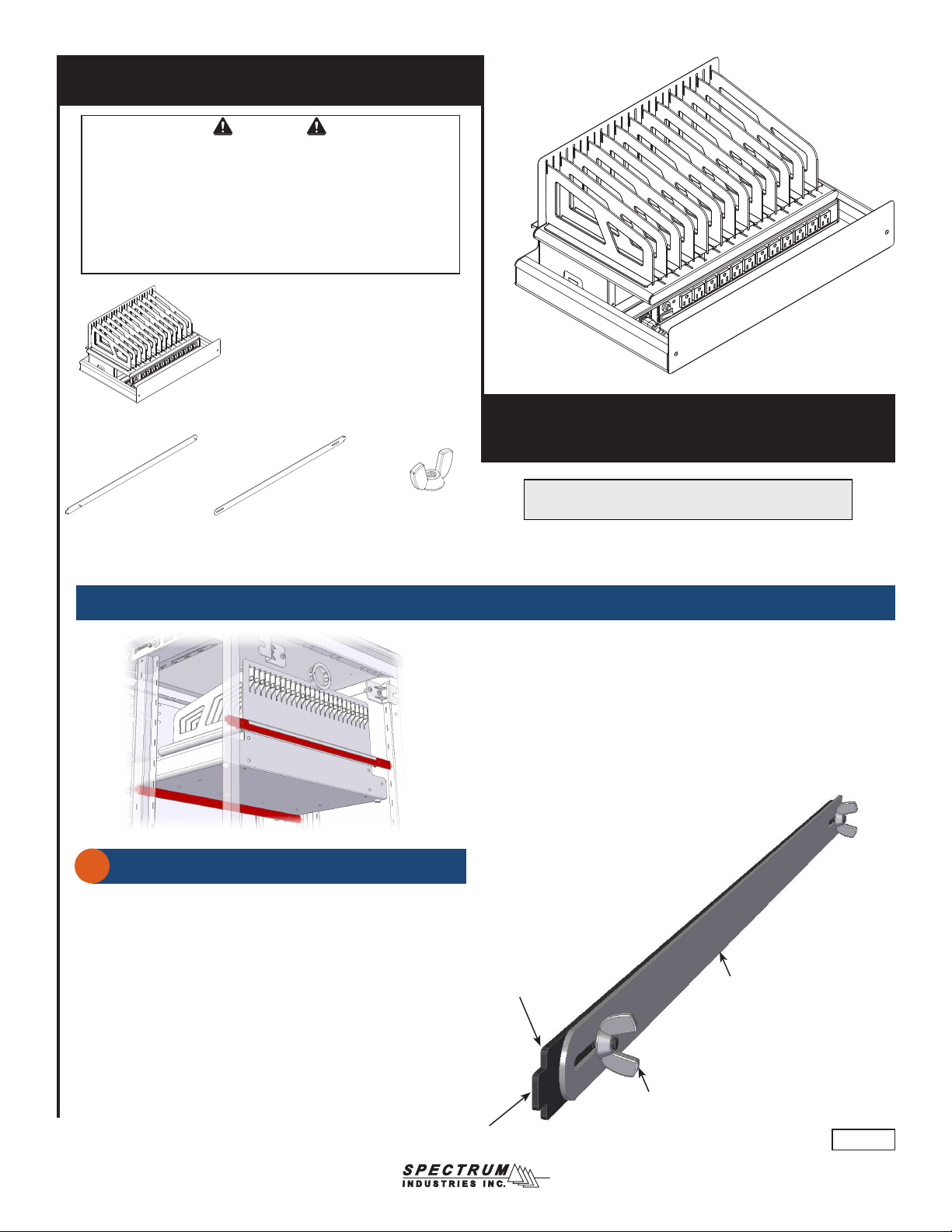
The Device Charging Module can store and charge up to
12 devices (most Chromebooks, tablets, or notebooks).
(1) Mobile device module
55506-H0 - no power
55506-HA - w/ AC power strip (12 outlets)
55506-HC - w/ (2) 6-port USB chargers
Assembled bars
Figure 1
Bar support B-side
(with slots)
Bar support
(with threaded weld studs)
Tab
Tab
8-32 Wing nut
(2 per assembly)
1
Installing module into cart or Techcenter (skip to p.3 for stand-alone module)
1. The bars should be assembled with the tabs facing away from each
other as shown in Figure 1.
2. Loosen the (2) wing nuts slightly.
3. Repeat for the 2nd set of bars.
Front bar Assembly
Rear bar Assembly
0191401R2 Page 2 of 4
Note: When determining the location of the module, be sure the module
will clear any obstructions that may be inside the cabinet and enough
clearance (height) is provided for all module devices.
Figure 2
Left slotted
uprights
Right slotted
uprights
1. Carefully set the empty module onto both sets of bars. Be sure the
rear channel “hooks” the rear set of bars fully. Figure 3.
Rear
channel
Figure 3
Bars
Bars
Device Module
Installing bars
2
Installing module
3
1. Determine the approximate location (height) you would like the
module to be mounted. The rear bar is (2) slots higher than the front.
2. Insert one tab into a slot in the left slotted upright. Figure 2.
3. Insert the opposite tab into the corresponding right slotted upright
and fully extend the bar assembly into place.
4. Lock the extended position of the bars by securely tightening the (2)
wingnuts. Be sure both wingnuts are tight.
5. Repeat for the 2nd set of bars.
X 12
0191401R2 Page 3 of 4
1. Place devices into bays with the charge plug accessible on top or front.
Figure 4.
2. With power cord unplugged and power switched OFF, plug chargers
into outlets.
3. Place chargers and excess cords behind power strip under devices.
Figure 4
CAUTION
While the rubber feet on the bottom of the module prevent scratching
of surfaces the module is placed on, screw heads protruding under the
unit can still possibly scratch these surfaces in some circumstances.
Place the module on a level surface using all 4 rubber feet. Do not
drag or slide the module across tables or worksurfaces. Use caution
when moving. Always remove all devices to reduce weight, and unplug
power strip prior to moving.
Device
Removal:
1. Press and hold the locking tab and slide the divider forward.
2. Lift divider out of slot. Figure 5.
Figure 5
Installation:
1. Insert divider into slot.
2. Slide back and ‘click’ into place.
Locking
tab
Dividers can be easily recongured for different devices if needed.
2
1
Installing devices
Dividers
0191401R2 Page 4 of 4
925 FIRST AVENUE, CHIPPEWA FALLS, WI 54729 / 800-235-1262 / 715-723-6750 / WWW.SPECTRUMFURNITURE.COM
© 2019 Spectrum Industries Inc., All rights reserved.
Electrical Specs
• 12-outlets, .83A max each
• 125VAC, 12A max, 60Hz
• 15-amp breaker
• IEC quick-release (replaceable) 8’ nominal, 14 AWG, 3-wire power cord
• ETL recognized (certied to 60950-1)
CAUTION
Keep power switched OFF when plugging in power cord to wall outlet or
device chargers into the power strip.
The user should be aware of the amp draw of the devices used with this
module-especially when maxing out the storage and charging capacity.
Exceeding 15 amps will trip the circuit breaker. Please consult the owners
manual of your specic device for power consumption information.
Figure 6.1Figure 6.2
IEC Inlet for
8’ power cord
Reset button
Power switch
12-outlets
8’ nominal [244 cm] 14 AWG,
3-wire IEC power cord
(to wall outlet)
Power Strip (if equipped)
Note: If USB chargers are included, install them inside
the tray (under the dividers) and connect to power.
USB chargers (if equipped)

This manual suits for next models

3

Other Spectrum Batteries Charger manuals

Spectrum 99057 User manual

Spectrum

Spectrum 99057 User manual

Spectrum InTouch 20 Cart with Sync Charge User manual

Spectrum

Spectrum InTouch 20 Cart with Sync Charge User manual

Spectrum Smart S150 User manual

Spectrum

Spectrum Smart S150 User manual

Spectrum 55505A0 User manual

Spectrum

Spectrum 55505A0 User manual

Popular Batteries Charger manuals by other brands

Fullwat FUM - 1205CBP user manual

Fullwat

Fullwat FUM - 1205CBP user manual

Somogyi home NVE 3/USB instruction manual

Somogyi

Somogyi home NVE 3/USB instruction manual

GRAUPNER ULTRA DUO PLUS 30 operating manual

GRAUPNER

GRAUPNER ULTRA DUO PLUS 30 operating manual

ChargePoint CPF50 installation guide

ChargePoint

ChargePoint CPF50 installation guide

DSR INC-700A owner's manual

DSR

DSR INC-700A owner's manual

William Sound CHG 863 user manual

William Sound

William Sound CHG 863 user manual

TE Connectivity IEC62196-2 Type II manual

TE Connectivity

TE Connectivity IEC62196-2 Type II manual

Makita Makstar DC18SD manual

Makita

Makita Makstar DC18SD manual

Greenlee LBC-81B instruction manual

Greenlee

Greenlee LBC-81B instruction manual

Associated Equipment 9640 Operator's manual

Associated Equipment

Associated Equipment 9640 Operator's manual

Belkin F8Z498cw user manual

Belkin

Belkin F8Z498cw user manual

Lester 18360 manual

Lester

Lester 18360 manual

Pepper Charging Station Guide

Pepper

Pepper Charging Station Guide

Turnigy Reactor user manual

Turnigy

Turnigy Reactor user manual

HIKOKI UC 18YTSL Handling instructions

HIKOKI

HIKOKI UC 18YTSL Handling instructions

CS-Electronic Professional X2 Charger manual

CS-Electronic

CS-Electronic Professional X2 Charger manual

Victron energy Blue Power IP22 manual

Victron energy

Victron energy Blue Power IP22 manual

Nexxtender Mobile Black T2 Driver manual

Nexxtender

Nexxtender Mobile Black T2 Driver manual

manuals.online logo
manuals.online logoBrands
  • About & Mission
  • Contact us
  • Privacy Policy
  • Terms and Conditions

Copyright 2025 Manuals.Online. All Rights Reserved.