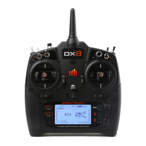
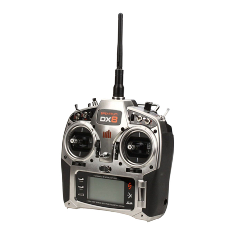
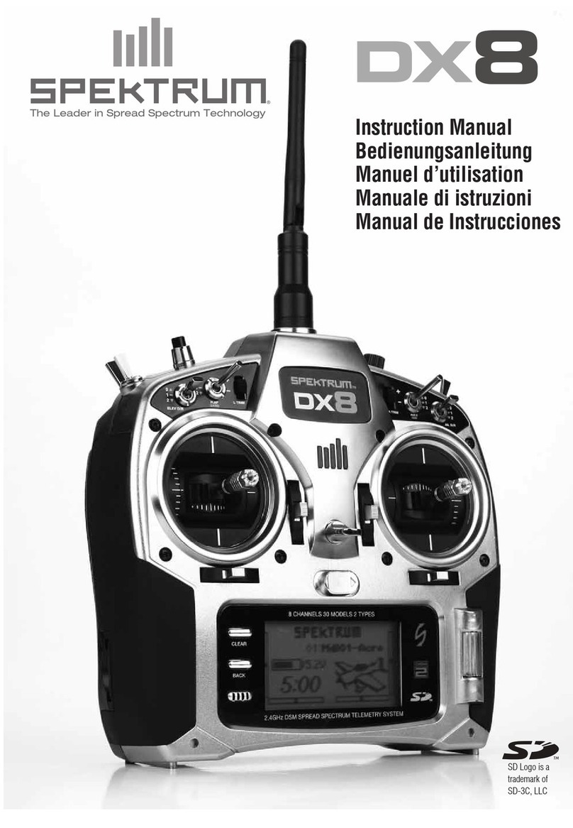
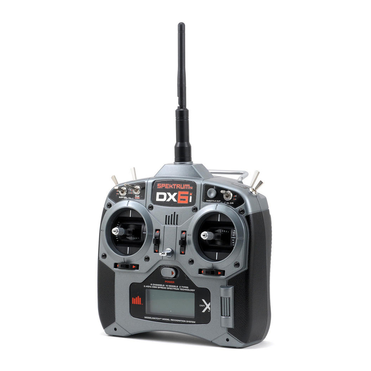
Spectrum DX8 User manual

SPEKTRUm
Innovative Spread Spectrum Technology
Sailplane Instruction Manual
Bedienungsanleitung Segelflugzeuge
Manuel d'utilisation planeur Manuale di
istruzioni per Aliante
NOTICE
All instructions, warranties and other collateral documents are subject to change at the sole discretion of Horizon Hobby, Inc. For up-
to-date product literature, visit horizonhobby.com and clic on the support tab for this product._____________________________
Meaning of Special Language
The following terms are used throughout the product literature to indicate various levels of potential harm when operating this product:
NOTICE: Procedures, which if not properly followed, create a possibility of physical property damage AND little or no possibility of injury.
Bind-N-Fly." Ready to fly,
redefined.
□smj
/I

CAUTION: Procedures, which if not properly followed, create the probability of physical property damage AND a possibility of serious injury.
WARNING: Procedures, which if not properly followed, create the probability of property damage, collateral damage and serious injury OR create
a high probability of superficial injury.
WARNING: Read the ENTIRE instruction manual to become familiar with the features of the product before operating. Failure to operate
the product correctly can result in damage to the product, personal property and cause serious injury.
This is a sophisticated hobby product. It must be operated with caution and common sense and requires some basic mechanical ability. Failure to
operate this Product in a safe and responsible manner could result in injury or damage to the product or other property. This product is not
intended for use by children without direct adult supervision. Do not attempt disassembly, use with incompatible components or augment product in
any way without the approval of Horizon Hobby, Inc. This manual contains instructions for safety, operation and maintenance. It is essential to read
and follow all the instructions and warnings in the manual, prior to assembly, setup or use, in order to operate correctly and avoid damage or
serious injury.
WARNING AGAINST COUNTER EIT PRODUCTS
Always purchase from a Horizon Hobby, Inc. authorized dealer to ensure authentic high-quality Spe trum product. Horizon Hobby,
Inc. disclaims all support and warranty with regards, but not limited to, compatibility and performance of counterfeit products or products claiming
compatibility with DSM or Spe trum.
NOTICE: This product is only intended for use with unmanned, hobby-grade, remote-controlled vehicles and aircraft. Horizon Hobby disclaims all
liability outside of the intended purpose and will not provide warranty service related thereto.
Age Recommendation: Not for Children under 14 years. This is not a toy.
WARRANTY REGISTRATION
Visit community.spe trumrc.com today to register your product.
NOTICE: While DSMX allows you to use more than 40 transmitters simultaneously, when using DSM2 receivers, DSMX receivers in DSM2 mode
or transmitters in DSM2 mode, do not use more than 40 transmitters simultaneously.
GENERAL NOTES
•Models are hazardous when operated and maintained incorrectly.
•Always install and operate a radio control system correctly.
•Always pilot a model so the model is ept under control in all
conditions.
•Please see help from an experienced pilot or your local hobby
store.
•Contact local or regional modeling organizations for guidance and
instructions about flying in your area.
•When wor ing with a model, always power on the transmitter first
and power off the transmitter last.
•After a model is bound to a transmitter and the model is set up in
the transmitter, always bind the model to the transmitter again to
establish failsafe settings.
PILOT SA ETY
•Always ma e sure all batteries are fully charged before flying.
•Time flights so you can fly safely within the time allotted by your
battery.
•Perform a range chec of the transmitter and the model before
flying the model.
•Ma e sure all control surfaces correctly respond to transmitter
controls before flying.
•Do NOT fly a model near spectators, par ing areas or any other
area that could result in injury to people or damage to property.
•Do NOT fly during adverse weather conditions. Poor visibility,
wind, moisture and ice can cause pilot disorientation and/or loss of
control of a model.
•When a flying model does not respond correctly to controls, land
the model and correct the cause of the problem.
A
A

•
With the new DX8 sailplane AirWare™ firmware update, the
Spe trum™ DX8 DSMX® transmitter now features full sailplane support
for the discerning sailplane pilot. Fully configurable to accommodate 4
servo wings, V-tails, and up to 4 flight modes; setting up your
sophisticated sailplane has never been easier! You'll have the flexibility
to set up your flap/airbra e/crow functions differently for each flight
mode, and its built-in Camber system enables you to have full camber
control from the throttle stic or auxiliary nob. Common mixing such as
Aileron to Flap, Aileron to Rudder, and Elevator to Flap is simple and
straight forward, plus setting differential for the Ailerons and Flap in
each flight mode is easy. There are 6 free programmable mixes
available and even a Flap to Elevator mix that features a 5-point curve.
Whatever configuration you are comfortable with for your high-
performance sailplane, the new DX8 sailplane AirWare update has
options to suit your needs.
BE ORE USING YOUR TRANSMITTER:
Before going any further, visit the Spe trum Community website at community.spe trumrc.com to register your transmitter and download the latest
AirWare firmware updates.
DX8 Sailplane eatures
The ey to this new software is in its ability to handle up to 4 flight modes with all the setup options a sailplane pilot could want. Than s to built-
in mixing, setting up airbra e/crow functions are easy
4 light Modes- can be assigned to any 2 switches
Launch Cruise
Speed Thermal
Sailplane Types- 4 wing types available
(a)servo aileron 2 servo ailerons
(b)ailerons 1 flaps 2 ailerons 2 flaps Tail
Types- 3 tail types available
Normal V-Tail A V-Tail B
Motor
Supports motor function on throttle stic or
programmable switch
Camber System
Full trailing edge camber can be adjusted in flight via
stic or nob. Different camber values are available in
each flight mode (4). Bra e/ Crow is available per flight
mode. Camber Preset
4 camber presets available (1 for each flight mode) for
flaps, ailerons and elevator
lap to Elevator Curve Mix
A flap to elevator curve mix can be assigned to and flight
mode or switch
Aileron to lap Mix
Aileron to Rudder Mix
Elevator to lap Mix
includes offset for snap flap mixing
Six ree Programmable Mixes
our Aileron Differential Settings
selectable in each flight mode
our lap Differential Settings
selectable in each flight mode
Elevator Trim Per light Mode
allows active independent elevator trimming per flight
mode
3SPEKTRUM DX8 • SAILPLANE INSTRUCTION MANUAL
EN

TABLE O CONTENTS
-Mode Setup ..................................................................................................................................................................... 4
SAIL (Sailplane) .................................................................................................................................................................. 4
Sailplane Type................................................................................................................................................................4
Trim................................................................................................................................................................................. 4
Camber Preset............................................................................................................................................................... 5
Camber System.............................................................................................................................................................. 5
SAIL Mixing.................................................................................................................................................................... 5
Differential...................................................................................................................................................................... 5
AMA National Model Aircraft Safety Code ........................................................................................................................ 6
CC Information ................................................................................................................................................................. 7
AA Information ................................................................................................................................................................. 7
LIMITED WARRANTY ......................................................................................................................................................... 8
Warranty and Service Contact Information ...................................................................................................................... 9
Compliance Information for the European Union ............................................................................................................ 9

Declaration of Conformity
9 -MODE
SETUP
Sailplane
Flight Mode
Setup
You can assign
up to four flight
modes using
any
combination of
up to two
switches.
Mode
Setup
E
E
S
3or 3
light
Modes:
Mode
4or 4
light
Modes:
Inhibit
light Mode: Launch
SAIL (Sailplane)
NOTICE: Refer to your
sailplane manual for
recommended control
throws.
CAUTION: Always do a
Control Test of your model
with ^ the transmitter after
programming to ma e sure
your model responds as
desired.
Sailplane Type
Use the Wing Type Screen to
select wing and tail types to
match your sailplane model.
Diagrams and setup names
show on the transmitter
screen to show the available
setups.
W
i
n
g
:
E
l
ii
l
Use the Flight Mode Setup menu to assign switches to
flight modes.
Mode Number of Switches Number of light Modes
Sailplane 2 4
ing
Normal
Dual Ailerons* 2
Aileron 1 Flap* 2
Aileron 2 Flap*
bJing Type ILI5T
A
Tail
Normal
V-Tail A
V-Tail B
x
/
EN
5SPEKTRUM DX8 • SAILPLANE INSTRUCTION MANUAL

£
F
l
a
p
s
T
a
il
fj
-
T
a
il
"
fl
1
M
o
t
o
r
:
I
n
h
i
b
it
Motor
Inhibit
Assign to a Switch
(optional) *Selection of
multiple ailerons activates
the Differentia! menu option.
Trim
In Sailplane mode, under trim
setup the elevator is set by
default to Common. This is can
be changed to F Mode so that
the sailplane can be trimmed
in pitch in every flight mode.
Camber
Preset
Camber Preset
is only available
when 2 aileron
wing type is
selected in Wing
Type. The
Camber Preset
function enables
you to program
the ailerons,
flaps and
elevator
for a
specific
position
in each
Flight
Mode.
If flight
modes
are
inactive,

only one preset
position is
available and it
is always active.
The
Camber
Preset
Speed
enables the
control
surfaces to
transition
over a
period of
time, up to
30
seconds,
when you
change
flight
modes.
Camber
Presets
Q
Ef
i
lap
JiEle
v X
Ail X
Laun
ch: 0
0 0+-
Cruis
e:
O
O
O
Ther
mal:
0 0 0
______
Speed
: Norm
Move the flight mode switch to the desired position to change the
Camber Preset values.
EN
7SPEKTRUM DX8 • SAILPLANE INSTRUCTION MANUAL

Camber System
Camber System is only available when 2 aileron wing type is selected in Wing Type. The Camber System allows in-flight camber
adjustment and is also used as the bra ing system, often referred to as Crow or Butterfly. The Camber System enables you to
assign the Camber System to the Spoiler Stic , right or left trimers or the Right Knob for each flight mode.
SAIL Mixing
For each of these mixes, you can program each flight mode with different mix values or at 0% if no mix is desired for that specific flight mode.
Programming values include independent control of the direction and the amount a slave surface moves in relationship to the master surface.
Aileron to Rudder
The Aileron to Rudder mix is a commonly used for coordinated turns. When active, as aileron is applied the rudder moves in the same
direction as the turn (right aileron input results in right rudder output).
Aileron to Flap
The Aileron to Flap mix allows the entire trailing edge of the wing (aileron and flap) to operate
as ailerons. When active, as aileron is applied the flaps also move. Always program the
flaps to move in the same direction as the turn (so that right aileron is equivalent to flaps
moving as right ailerons).
Elevator to Flap
Elevator to Flap mix creates more lift, allowing a tighter turn by applying down flap with up
elevator. An offset is provided which is typically used for Snap Flaps. With Snap Flap, no
Elevator to Flap mix occurs until the offset value is reached. Typically this offset is at 70%
up elevator so that beyond 70% the down flap mix comes in, providing additional lift for
more aggressive turning (for tight thermals or racing turns).
Flap to Elevator
Flap to Elevator mix prevents pitch up tendency that occurs when bra es (Crow or Butterfly)
are applied. This mix is typically used only with the bra e system (See Camber system).
This mix operates as a curve, so that the elevator typically moves down most during the first
20% of flap deployment, decreases over the next 40% then remains the same from 60 to
100% of flap travel.
Differential
The Differential function decreases the amount an aileron moves down
without affecting the amount the other aileron moves up. This can
decrease adverse yaw (right or left movement of the aircraft nose)
tendencies during roll maneuvers. Positive (+) and negative (-)
differential is available; however, normally more up (+) aileron travel is
required than down (-). Assign a switch to enable differential values during
flight or select "On" so that differential is always enabled.
Differential um
Cruise
laps: Q Y.
Ailerons: O X Switch: M
Camber System IllS
Launcn Input:
Inhibit Offset: 0
V.
Up Down laps: 0 0
Ailerons: 0 0

AMA NATIONAL MODEL AIRCRA T SA ETY CODE
Effective January 1, 2011
A. GENERAL: A model aircraft is a non-human-
carrying aircraft capable of sustained flight in
the atmosphere. It may not exceed limitations
of this code and is intended exclusively for
sport, recreation and/or competition. All model
flights must be conducted in accordance with
this safety code and any additional rules
specific to the flying site.
1.Model aircraft will not be flown:
(a)In a careless or rec less manner.
(b)At a location where model aircraft
activities are prohibited.
2.Model aircraft pilots will:
(a)Yield the right of way to all man
carrying aircraft.
(b)See and avoid all aircraft and a spotter
must be used when appropriate.
(AMA Document #540-D-See and
Avoid Guidance.)
(c)Not fly higher than approximately
400 feet above ground level within
three (3) miles of an airport,
without notifying the airport
operator.
(d)Not interfere with operations and
traffic patterns at any airport,
heliport or seaplane base except
where there is a mixed use
agreement.
(e)Not exceed a ta eoff weight,
including fuel, of 55 pounds unless
in compliance with the AMA Large
Model Aircraft program. (AMA
Document 520-A)
(f)Ensure the aircraft is identified with the
name and address or AMA number of
the owner on the inside or affixed to
the outside of the model aircraft. (This
does not apply to model aircraft flown
indoors).
(g)Not operate aircraft with metal-
blade propellers or with gaseous
boosts except for helicopters
operated under the provisions of
AMA Document #555.
(h)Not operate model aircraft while under
the influence of alcohol or while using
any drug which could adversely affect
the pilot's ability to safely control the
model.
(i)Not operate model aircraft carrying
pyrotechnic devices which explode or
burn, or any device which propels a
projectile or drops any object that
creates a hazard to persons or
property.
Exceptions:
•Free Flight fuses or devices that
burn producing smo e and
are securely attached to the
model aircraft during flight.
•Roc et motors (using solid
propellant) up to a G-series
size may be used provided
they remain attached to the
model during flight. Model
roc ets may be flown in
accordance with the National
Model Roc etry Safety Code
but may not be launched from
model aircraft.
•Officially designated AMA Air
Show Teams (AST) are
authorized to use devices and
practices as defined within the
Team AMA Program
Document (AMA Document
#718).
(j) Not operate a turbine-powered aircraft,
unless in compliance
with the AMA turbine regulations. (AMA
Document #510-A).
3.Model aircraft will not be flown in AMA
sanctioned events, air shows or model
demonstrations unless:
(a)The aircraft, control system and pilot
s ills have successfully demonstrated
all maneuvers intended or anticipated
prior to the specific event.
(b)An inexperienced pilot is assisted by an
experienced pilot.
4.When and where required by rule, helmets
must be properly worn and fastened. They
must be OSHA, DOT, ANSI, SNELL or
NOCSAE approved or comply with
comparable standards.
B. RADIO CONTROL (RC)
1.All pilots shall avoid flying directly over
unprotected people, vessels, vehicles or
structures and shall avoid endangerment of
life and property of others.
2.A successful radio equipment ground-range
chec in accordance with manufacturer's
recommendations will be completed before
the first flight of a new or repaired model
EN
9SPEKTRUM DX8 • SAILPLANE INSTRUCTION MANUAL

aircraft.
3.At all flying sites a safety line(s) must be
established in front of which all flying ta es
place (AMA Document #706-Recommended
Field Layout):
(a)Only personnel associated with flying the
model aircraft are allowed at or in front
of the safety line.
(b)At air shows or demonstrations, a straight
safety line must be established.
(c)An area away from the safety line must
be maintained for spectators.
(d)Intentional flying behind the safety line is
prohibited.
4.RC model aircraft must use the radio-control
frequencies currently allowed by the
Federal Communications Commission
(FCC). Only individuals properly licensed by
the FCC are authorized to operate
equipment on Amateur Band frequencies.
5.RC model aircraft will not operate within three
(3) miles of any pre-existing flying site
without a frequency-management
agreement (AMA Documents #922-Testing
for RF Interference; #923- Frequency
Management Agreement)
6.With the exception of events flown under
official AMA Competition Regulations,
excluding ta eoff and landing, no powered
model may be flown outdoors closer than
25 feet to any individual, except for the pilot
and the pilot's helper(s) located at the flight
line.
7.Under no circumstances may a pilot or other
person touch a model aircraft in flight while
it is still under power, except to divert it from
stri ing an individual. This does not apply to
model aircraft flown indoors.
8.RC night flying requires a lighting system
providing the pilot with a clear view of the
model's attitude and orientation at all times.
9.The pilot of a RC model aircraft shall:
(a)Maintain control during the entire flight,
maintaining visual contact without
enhancement other than by corrective
lenses prescribed for the pilot.
(b)Fly using the assistance of a camera or
First-Person View (FPV) only in
accordance with the procedures
outlined in AMA Document #550.
Please see your local or regional modeling
association's guidelines for proper, safe
operation of your model aircraft.

This device complies with part 15 of the FCC
rules. Operation is subject to the following
two conditions: (1) This device may not
cause harmful interference, and (2) this
device must accept any interference
received, including interference that may
cause undesired operation.
CAUTION: Changes or
modifications not expressly approved
by the party responsible for compliance could
void the user's authority to operate the
equipment. This product contains a radio
transmitter with wireless technology which
has been tested and found to be compliant
with the applicable regulations governing a
radio transmitter in the 2.400GHz to
2.4835GHz frequency range.
This product contains a radio transmitter with
wireless technology which has been tested
and found to be compliant with the applicable
regulations governing a radio transmitter in
the 2.400GHz to 2.4835GHz frequency
range.
ANTENNA SEPARATION DISTANCE
When operating your Spe trum transmitter,
please be sure to maintain a separation
distance of at least 5 cm between your body
(excluding fingers, hands, wrists, an les and
feet) and the antenna to meet RF exposure
safety requirements as determined by FCC
regulations.
The following illustrations show the
approximate 5 cm RF exposure area and
typical hand placement when operating your
Spe trum transmitter.
AA IN ORMATION_______________________________________________________
Prior to flying, contact your local or regional modeling organizations for guidance and familiarize
yourself with the current local rules and FAA regulations governing model aviation in your
location.
More information about model aviation can be found at www.modelaircraft.org.
The Federal Aviation Administration can be found online at www.faa.gov.
CC IN ORMATION
A
EN
11 SPEKTRUM DX8 • SAILPLANE INSTRUCTION MANUAL

1-YEAR LIMITED WARRANTY
What this Warranty Covers
Horizon Hobby, Inc.,
(Horizon) warrants to the
original purchaser that the
product purchased (the
"Product") will be free from
defects in materials and
wor manship for a period of 1
years from the date of
purchase. What is Not
Covered
This warranty is not
transferable and does not
cover (i) cosmetic damage,
(ii) damage due to acts of
God, accident, misuse,
abuse, negligence,
commercial use, or due to
improper use, installation,
operation or maintenance, (iii)
modification of or to any part
of the Product, (iv) attempted
service by anyone other than
a Horizon Hobby authorized
service center, (v) Product
not purchased from an
authorized Horizon dealer, or
(vi) Product not compliant
with applicable technical
regulations.
OTHER THAN THE
EXPRESS WARRANTY
ABOVE, HORIZON MAKES
NO OTHER WARRANTY OR
REPRESENTATION, AND
HEREBY DISCLAIMS ANY
AND ALL IMPLIED
WARRANTIES, INCLUDING,
WITHOUT LIMITATION, THE
IMPLIED WARRANTIES OF
NON-INFRINGEMENT,
MERCHANTABILITY AND
FITNESS FOR A
PARTICULAR PURPOSE.
THE PURCHASER
ACKNOWLEDGES THAT
THEY ALONE HAVE
DETERMINED THAT THE
PRODUCT WILL SUITABLY
MEET THE
REQUIREMENTS OF THE
PURCHASER'S INTENDED
USE. Purchaser's Remedy
Horizon's sole obligation and
purchaser's sole and
exclusive remedy shall be
that Horizon will, at its option,
either (i) service, or (ii)
replace, any Product
determined by Horizon to be
defective. Horizon reserves
the right to inspect any and
all Product(s) involved in a
warranty claim. Service or
replacement decisions are at
the sole discretion of Horizon.
Proof of purchase is required
for all warranty claims.
SERVICE OR
REPLACEMENT AS
PROVIDED UNDER THIS
WARRANTY IS THE
PURCHASER'S SOLE AND
EXCLUSIVE REMEDY.
Limitation of Liability
HORIZON SHALL NOT BE
LIABLE FOR SPECIAL,
INDIRECT, INCIDENTAL OR
CONSEQUENTIAL
DAMAGES, LOSS OF
PROFITS OR PRODUCTION
OR COMMERCIAL LOSS IN
ANY WAY, REGARDLESS
OF WHETHER SUCH CLAIM
IS BASED IN CONTRACT,
WARRANTY, TORT,
NEGLIGENCE, STRICT
LIABILITY OR ANY OTHER
THEORY OF LIABILITY,
EVEN IF HORIZON HAS
BEEN ADVISED OF THE
POSSIBILITY OF SUCH
DAMAGES. Further, in no
event shall the liability of
Horizon exceed the individual
price of the Product on which
liability is asserted. As
Horizon has no control over
use, setup, final assembly,
modification or misuse, no
liability shall be assumed nor
accepted for any resulting
damage or injury. By the act
of use, setup or assembly,
the user accepts all resulting
liability. If you as the
purchaser or user are not
prepared to accept the
liability associated with the
use of the Product, purchaser
is advised to return the
Product immediately in new
and unused condition to the
place of purchase. Law
These terms are governed by
Illinois law (without regard to
conflict of law principals). This
warranty gives you specific
legal rights, and you may also
have other rights which vary
from state to state. Horizon
reserves the right to change
or modify this warranty at any
time without notice.

WARRANTY SERVICES
Questions, Assistance,
and Services
Your local hobby store and/or
place of purchase cannot
provide warranty support or
service. Once assembly,
setup or use of the Product
has been started, you must
contact your local distributor
or Horizon directly. This will
enable Horizon to better
answer your questions and
service you in the event that
you may need any
assistance. For questions or
assistance, please visit our
website at
www.horizonhobby.com,
submit a Product Support
Inquiry, or call the toll free
telephone number referenced
in the Warranty and Service
Contact Information section
to spea with a Product
Support representative.
Inspection or Services
If this Product needs to be
inspected or serviced and is
compliant in the country you
live and use the Product in,
please use the Horizon
Online Service Request
submission process found on
our website or call Horizon to
obtain a Return Merchandise
Authorization (RMA) number.
Pac the Product securely
using a shipping carton.
Please note that original
boxes may be included, but
are not designed to withstand
the rigors of shipping without
additional protection. Ship via
a carrier that provides
trac ing and insurance for
lost or damaged parcels, as
Horizon is not responsible for
merchandise until it arrives
and is accepted at our
facility. An Online Service
Request is available at
http://www.
horizonhobby.com/content/_s
ervice-center_render-service-
center. If you do not have
internet access, please
contact Horizon Product
Support to obtain a RMA
number along with
instructions for submitting
your product for service.
When calling Horizon, you
will be as ed to provide your
complete name, street
address, email address and
phone number where you
can be reached during
business hours. When
sending product into Horizon,
please include your RMA
number, a list of the included
items, and a brief summary
of the problem. A copy of
your original sales receipt
must be included for
warranty consideration. Be
sure your name, address,
and RMA number are clearly
written on the outside of the
shipping carton.
NOTICE: Do not ship
LiPo batteries to Horizon.
If you have any issue
with a LiPo battery,
please contact the
appropriate Horizon
Product Support office.
Warranty Requirements
or Warranty
consideration, you must
include your original
sales receipt verifying
the proof-of-purchase
date. Provided warranty
conditions have been met,
your Product will be serviced
or replaced free of charge.
Service or replacement
decisions are at the sole
discretion of Horizon.
Non-Warranty Service
Should your service not
be covered by warranty,
service will be completed
and payment will be
required without
notification or estimate of
the expense unless the
expense exceeds 50% of
the retail purchase cost.
By submitting the item for
service you are agreeing to
payment of the service
without notification. Service
estimates are available upon
request. You must include
this request with your item
submitted for service. Non-
warranty service estimates
will be billed a minimum of /
hour of labor. In addition you
will be billed for return freight.
Horizon accepts money
orders and cashier's chec s,
as well as Visa, MasterCard,
American Express, and
Discover cards. By
submitting any item to
Horizon for service, you are
EN
13 SPEKTRUM DX8 • SAILPLANE INSTRUCTION MANUAL

agreeing to Horizon's Terms
and Conditions found on our
website
http://www.horizonhobby.
com/content/_service-
center_render-service-center.
ATTENTION:
Horizon service is
limited to Product
compliant in the
country of use and
ownership. If
received, a non-
compliant Product
will not be
serviced. urther,
the sender will be
responsible for
arranging return
shipment of the un-
serviced Product,
through a carrier of
the sender's
choice and at the
sender's expense.
Horizon will hold
non-compliant
Product for a
period of 60 days
from notification,
after which it will
be discarded.

WARRANTY AND SERVICE CONTACT IN ORMATION
COMPLIANCE IN ORMATION OR THE EUROPEAN UNION
Declaration of Conformity
(in accordance with ISO/IEC 17050-1) No.
HH2010080203
SPM DX8 Transmitter SPM8800EU, SPMR8800EU 2
The object of declaration described above is in conformity with the requirements
of the specifications listed below, following the provisions of the European
R&TTE directive 1999/5/EC:
EN 60950 Safety
EN 300-328 Technical requirements for Radio equipment EN 301 489
General EMC requirements for Radio equipment
Signed for and on behalf of: Horizon Hobby, Inc. Champaign, IL USA Aug 02,
2010
Instructions for disposal of WEEE by users in
the European Union
This product must not be disposed of with other waste. Instead, it is the user's
responsibility to dispose of their waste equipment by handing it over to a
designated collections point for the recycling of waste electrical and electronic
equipment. The separate collection and recycling of your waste equipment at
the time of disposal will help to conserve natural resources and ensure that it is
recycled in a manner that protects human health and the environment. For
more information about where you can drop off your waste equipment for
recycling, please contact your local city office, your household waste disposal
service or where you purchased the product.
Steven A. Hall
Executive Vice President and Chief Operating Officer International Operations and Ris Management Horizon Hobby, Inc
15 SPEKTRUM DX8 • SAILPLANE INSTRUCTION MANUAL
Country of Purchase Horizon Hobby Contact Information Address
Horizon Service Center
(Repairs and Repair Requests)
servicecenter.horizonhobby.com/
RequestForm/
United States of Horizon Product Support
(Product Technical Assistance)
www.quic base.com/db/ bghj7ey8c?
a=GenNewRecord
4105 Fieldstone Rd
America Heli 888-959-2304 Air 888-959-2305 Champaign, Illinois, 61822 USA
sales@horizonhobby.com
Sales Heli 888-959-2304 Air 888-959-2305
United Kingdom Service/Parts/Sales: Horizon Hobby
Limited
sales@horizonhobby.co.u +44 (0) 1279
641 097
Units 1-4 , Ployters Rd, Staple Tye Harlow,
Essex, CM18 7NS, United Kingdom
Germany Horizon Technischer Service service@horizonhobby.de Christian-Junge-StraBe 1
Sales: Horizon Hobby GmbH +49 (0) 4121 2655 100 25337 Elmshorn, Germany
France Service/Parts/Sales: infofrance@horizonhobby.com 11 Rue Georges Charpa
Horizon Hobby SAS +33 (0) 1 60 18 34 90 77127 Lieusaint, France
China Service/Parts/Sales: info@horizonhobby.com.cn Room 506, No. 97 Changshou Rd.
Horizon Hobby - China +86 (021) 5180 9868 Shanghai, China 200060
Product(s): Item
Number(s):
Equipment class:
AT BE BG CZ CY DE DK
ES FI FR GR HU IE IT
LT LU LV MT NL PL PT
RO SE SI SK UK
EN

5PEKTRUITI.
Innovative Spread Spectrum Technology
© 2013 Horizon Hobby, Inc.
The Spe trum trademar is used with permission of Bachmann Industries, Inc.
DSMX, AirWare, SimpleScroll, JR, Vibe and Bind-N-Fly are trademar s or registered trademar s of Horizon Hobby, Inc.
SD Logo is a trademar of SD-3C, LLC
US 7,391,320. Other patents pending.
www.spe trum-rc.com
Other manuals for DX8
2
Table of contents
Other Spectrum Remote Control manuals

Spectrum
Spectrum DX6i User manual

Spectrum
Spectrum enbrighten UCL/44/3/39/12/120 User manual

Spectrum
Spectrum DX4R Pro User manual

Spectrum
Spectrum AR9000 User manual

Spectrum
Spectrum DX3S User manual

Spectrum
Spectrum DX6i User manual

Spectrum
Spectrum DX8 User manual

Spectrum
Spectrum URC1160 User manual

Spectrum
Spectrum URC1160 User manual

Spectrum
Spectrum DX8 Use and care manual