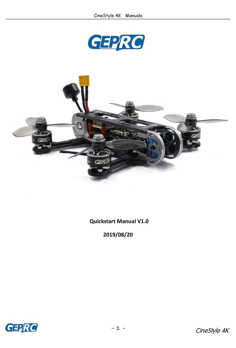
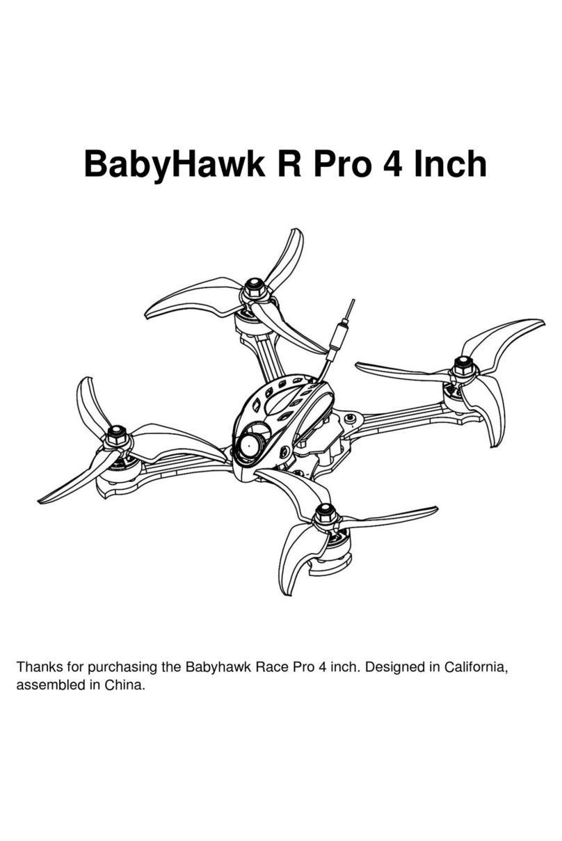
SPEDIX S250 Pro FPV User manual

S250 PRO
S250 Pro FPV Quadcopter Manual
Version: Naze V6 V1.1
www.spedix-rc.com
Features
Setup and Play.
Assembled and tested in factory.
Quick response in flight, durable and
light structure.
Latest Naze32 Rev6 flight controller
with 3 Flight modes.
DSM2/DSMX* compatible satellite
receiver with easy binding button.
700TVL FPV camera.
5.8GHz 200mW 40 channel video
transmitter with race band.
Integrated On Screen Display.
Powerful and durable 2204 motors.
BLHeli program speed controllers.
Green and Red LED lights on arms.
Programmable RGB LED lights on
tail.
*DSM2 and DSMX are trademarks of Horizon Hobby Inc.
The receiver installed in this aircraft is not a product of
Horizon Hobby Inc.
WARNING
For age 14+ only. Rotating propellers may cause serious injury and damages!
Do not install propellers during setup procedures.
Check www.knowbeforeyoufly.org for drone safety.
Users in USA need register on FAA system: www.federaldroneregistration.com
!Online Video Instructions
Scan barcode or search
“Spedix S250 Pro Setup” on
YouTube to acsess video
instructions.

Package Content
Optional Equipment
S250 Pro Quad x1 Propellers x4 Receiver Cable x1 OSD-ISP OSD-SET
Cable x1 Cable x1
6+ Channel
Spektrum Radio
3S or 4S
1500-1800mAh LiPo USB Cable FPV monitor or goggle

2. Binding the quad to a radio
The quad comes with a DSM2/DSMX compatible
satellite receiver. Please make sure your radio
system is DSM2/DSMX compatible. Otherwise you
may need to change the receiver of the quad, and
follow the installation instructions of your radio
system and Naze Rev6 flight controller.
The satellite has a binding button on the side.
Follow the following steps to finish binding.
1. Radio settings
DO NOT have propellers installed during setting procedures.
Unexpected startup may cause serious damages or injury.
The radio should set to
airplane mode.
5. Fight mode settings
In the mode tab, setup Aux1 switch for flight mode selection. Angle mode
is set in the factory as default and is recommended to beginners for its
stabilization function. Aux2 switch is set in factory to turn on/off beeper.
WARNING
!
2000
Roll
2000
Pitch
2000
Yaw
2000
Throttle
999
Roll
999
Pitch
999
Yaw
999
Throttle
1500
Roll
1500
Pitch
1500
Yaw
1500
Throttle
Set the middle point to 1500
Set the minimum range smaller than 1100
Set the maximum range bigger than 1900
Binding & Settings
Binding button
Sideview of
satellite receiver
Press and hold binding button
Power up the quad until satellite flashes rapidly
Release binding button.
LED stays on in DSMX mode.
LED flashes slowly in DSM2 mode.
3. Install Cleanflight configurator in your PC.
Go to Google Chrome web store and search the key word
“cleanflight” to install the software in Chrome. This is the
software to configure flight controller and your radio so that it
can start and control the quad properly.
The quad itself has been programmed in the factory and is
not necessary to make changes of the parameters for
beginners.
Online Video Instructions
Have trouble in binding and
settings? We have online video
tutorials. Scan barcode on the
right or search “Spedix S250
Pro Setup” on YouTube to
watch video instructions.
4. Cleanflight and receiver settings

Propeller rotation is the same as motors
M1
M4 M2
M3
Installation and Testing
Unlock throttle
(Power on)
Unlock throttle
(Power on)
Lock throttle
(Power off)
7. Lock and unlock throttle
For safety the throttle is locked in factory settings.
To unlock throttle and power on the quad move the throttle stick all
the way to the right lower corner.
8. Installation fo propellers
The rotation of propellers should be the same as indicated in the
right picture. The directions of factory propellers are shown on
the hub.
Motor Sequence
and Rotation
Propellers should be secured before flight.
Head
Tail
After the motors are powered on, check the rotation of motors to
confirm they are in the directions as shown in the right picture.
6. Motor calibration
Motors are calibrated in the factory. If they do not spin properly,
then motors should be calibrated in Cleanflight to make the quad
work properly. Follow the instructions in the software to complete
calibration.
WARNING
!

Display
Channels12345678
Bands: ABEFR with raceband
Long press to change to channel or band mode.
In channel mode, short press to change 12345678
In band mode, short press to change ABEFR
Specifications of VTX
Power: 200mW
Frequency: 5.8 GHz
Channels: 40 Channels, ABEFR Bands
Antenna: SMA 3dBi antenna
Power: 7-24V input
Size: 29x22x7.5mm
Weight: 8.3g
Power Consumption: 300 mA @12V MAX
Video Range: 300 meters in open area
Working Temperature: -10 to 65 Celsius degrees
Video Transmitter and OSD
!Important: Antenna should be installed
before power on.
Ch1 CH2 CH3 CH4 CH5 CH6 CH7 CH8
A57055685566556655885590559055905
B57335752577157905809582858475866
E57255745576558055785582558455865
F5740 5760578058005820584058605880
R5658 5695573257695806584358805917
Frequency Chart
RP-SMA Connector
5.8G Hz 200mW 40 Channel Video Transmitter
OSD
The flight controller of S250 Pro is integrated with the
popular On-Screen-Display module, MWOSD. Flight
information such as voltage, horizon can be added to the
video. Those basic functions are set in factory. There is no
need to change the settings for beginners. For advanced
settings please check MWOSD tutorials available on internet
and YouTube.
Software for the OSD can be downloaded from the
following link or by scanning the bar code below:
https://github.com/ShikOfTheRa/scarab-osd

Electronics
Main Control Board
S250 has a flight controller based on Naze32
Rev6, integrated with power distribution board
and MinimOSD. The flight controller is mounted
upside down in the quad. Therefore in the
Configuration section of Cleanflight, “Board
and Sensor Alignment” should be set to 180
roll degrees.
Definition of wires
Red - power (+)
Black - ground (-)
Yellow - signal
Connection of Electronic Components
Motor
ESC LED Plate
40 Channel
Video Transmitter
Antenna
Programmable
LED
Main Control
Board (mounted
upside down)
Satellite
Receiver
700TVL
FPV Camera
XT60 Connector
Spektrum Sattelite
5V
GND
VTX
Progrmamable
LED
Video
Audio
GND
5V
S
GND
OSD-SET OSD-ISP
GND
5V
OSD-RX
OSD-TX
OSD-DTR
GND
5V
OSD-RST
OSD-SCK
OSD-MISO
OSD-MOSI
UART2 TX
CPPM In
CH2
+5V
GND
UART2 RX(SBUS IN)
RX
TX
RX
TX
Bootloader Pads 5V
GND
Video
Audio
5V
12V
+
123
45
6
7
8Channel
Camera
Receiver In
USB

Assembly 1
Arm assembly
LED installation
Camera instrallation
Video Transmitter installation
Flight controller installation
M2x12
M2x8
M3x8
Landing Gear
ESC
ARM
2204 Motor
5’or 6'Propeller
ARM Led Plate

Assembly 2
Main Frame Assembly
YouTube Videos
Discussion on
RC Groups
Table of contents
