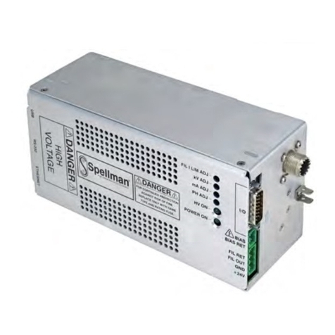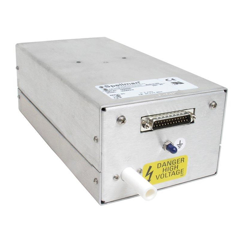
BEAM CONTROLLER INTERFACE—
25 PIN FEMALE D CONNECTOR
SPELLMAN HIGH VOLTAGE ELECTRONICS CORPORATION
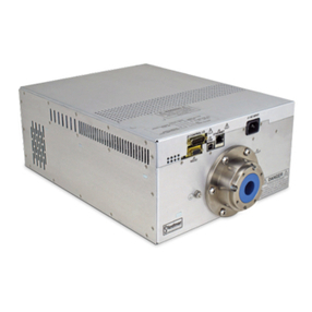
3/6/12kW EVAP
POWER SUPPLY
EVA
HV POWER SUPPLY INTERFACE—
50 PIN FEMALE D CONNECTOR
PIN SIGNAL PARAMETERS
1 Power Supply Common Power Supply Ground
2 Reset/HV Inhibit Normally open, Low = Reset/Inhibit
3 External Interlock +24Vdc @ open, <25mA @ closed
4 External Interlock Return Return for External Interlock
5 mA Test Point 0-10Vdc = 0-100% rated output, Zout= 1KΩ, 1%
6 kV Test Point 0-10Vdc = 0-100% rated output, Zout= 1KΩ, 1%
7 +10Vdc Reference Output +10Vdc @ 1mA
8 mA Program Input 0-10Vdc = 0-100% rated output, Zin>10MΩ
9 Local mA Program Output 0-10Vdc = 0-100% rated output, front panel pot
10 kV Program Input 0-10Vdc = 0-100% rated output, Zin>10MΩ
11 Local kV Program Output 0-10Vdc = 0-100% rated output, front panel pot
12 Remote Power On Output +24Vdc @ open, <25mA @ closed
13 Remote Power On Return Return for Remote Power On
14 Remote HV Off +24Vdc @ open, <25mA @ closed, connect to
pin15 for front panel operation
15 Remote HV Off/On Common HV On/Off Common
16 Remote HV On +24Vdc @ open, <25mA @ closed, momentarily
connect to pin 15 enable high voltage
17 HV Off Indicator +24Vdc @ 25mA = HV Off
18 HV On Indicator +24Vdc @ 25mA = HV On
19 Power Supply Common Supply Ground
20 +24Vdc Output +24Vdc @ 100mA, maximum
21 Voltage Mode Status Open Collector, Low = Active
22 Current Mode Status Open Collector, Low = Active
23 Power Mode Status Open Collector, Low = Active
24 Interlock Closed Status Open Collector, Low = Active
25 Power Test Point 0-10Vdc = 0-100% rated output, Zout= 5KΩ, 1%
26 Spare
27 Spare
28 Remote Overvoltage Adjust 0-10Vdc = 0-100% rated output
29 Over Power Fault Open Collector, Low = Active
30 Over Voltage Fault Open Collector, Low = Active
31 Over Current Fault Open Collector, Low = Active
32 System Fault Open Collector, Low = Active
33 RGLT Error Fault Open Collector, Low = Active
34 Arc Open Collector, Low = Active
35 Over Temp Fault Open Collector, Low = Active
36 AC Fault Open Collector, Low = Active
37 Spare
38 Spare
39 Spare
40 Spare
41 Spare
42 Remote Power Program Input 0-10Vdc = 0-100% rated output, Zin>10MΩ
43 Local Power Program Output 0-10Vdc = 0-100% rated output, internal pot
44 +5Vdc Output +5Vdc @ 100mA, maximum
45 +15Vdc Output +15Vdc @ 100mA, maximum
46 -15Vdc Output -15Vdc @ 10mA, maximum
47 RS232 Tx
48 RS232 Rx
49 RS232 GND
50 Power Supply Common Power Supply Ground
PIN SIGNAL SIGNAL PARAMETERS
1 Power Supply Common Signal Ground
2 Spare
3 External Interlock +15Vdc at Open, <15mA @ Closed
4 External Interlock Return Return for Interlock
5 Filament Current Test Point 0 to 10Vdc = 0 to 100% rated output
6 Beam Current Test Point 0 to 10Vdc = 0 to 100% rated output
7 +10Vdc Reference +10Vdc, 1mA Max
8 Filament Limit Program Input 0 to 10Vdc = 0 to 100% rated output
9 Local Filament Limit Program Front panel potentiometer wiper
10 Beam Current Program Input 0 to 10Vdc = 0 to 100% rated output
11 Local Beam Current Program Front panel potentiometer wiper
12 Filament Preheat Program In 0 to 10Vdc = 0 to 100% rated output
13 Local Fil. Preheat Program Internal potentiometer
14 Beam Off +15Vdc at Open, <25mA @ Closed
15 Beam On/Off Common Connect together for FP operation
16 Beam On Momentarily connect to pin 15 = Beam On
17 Remote Beam Off Indicator 0=Beam On, +15V, 10mA Max=Beam Off
18 Remote Beam On Indicator 0=Beam Off, +15V, 10mA Max=Beam On
19 Spare
20 Spare
21 Spare
22 Remote PS Fault 0 = Fault, +15Vdc @ 0.1mA = No Fault
23 Spare
24 Power Supply Common Signal Ground
25 Shield Return Chassis Ground
PAGE 4 OF 7
Corporate Headquarters
Hauppauge, New York USA
+1-631-630-3000 FAX: +1-631-435-1620
e-mail: sales@spellmanhv.com
www.spellmanhv.com 128106-001 REV. A
Spellman High Voltage is an ISO 9001:2008 and ISO 14001:2004 registered company
Copyright © 2014 Spellman High Voltage Electronics Corp.


