Caen 803 Series User manual

803x Series 8-16 Ch. Programmable HV Power Supplies
Rev. 10 - 19 December 2022

Purpose of this Manual
This document is the 803x Series 8-16 Ch. Programmable HV Power Supplies User's Manual; it
contains information about the installation, the configuration and the use of the units.
Change Document Record
Date
Revision
Changes
30 May 2019
0
Preliminary Release
20 December 2019
1
Updated power requirements
21 July 2020
2
Updated Technical specifications table
28 January 2021
3
Updated power requirements, Technical specifications table
5 February 2021
4
Updated Technical specifications table
25 February 2021
5
Updated power requirements, Technical specifications table
23 March 2021
6
Updated Technical specifications table
7 May 2021
7
Updated Technical specifications table, External connections
12 May 2021
8
Updated Software tools
8 June 2022
9
Updated power requirements, Technical specifications table
19 December 2022
10
Updated with 8034H series data
Manufacturer Contacts
CAEN S.p.A.
Via Vetraia, 11 55049 Viareggio (LU) - ITALY
Tel. +39.0584.388.398 Fax +39.0584.388.959
© CAEN SpA –2021
Limitation of Responsibility
If the warnings contained in this manual are not followed, CAEN will not be responsible for damage caused by improper
use of the device. The manufacturer declines all responsibility for damage resulting from failure to comply with the
instructions for use of the product. The equipment must be used as described in the user manual, with particular regard
to the intended use, using only accessories as specified by the manufacturer. No modification or repair can be performed.
Disclaimer
No part of this manual may be reproduced in any form or by any means, electronic, mechanical, recording, or otherwise,
without the prior written permission of CAEN spa. The information contained herein has been carefully checked and is
believed to be accurate; however, no responsibility is assumed for inaccuracies. CAEN spa reserves the right to modify
its products specifications without giving any notice; for up to date information please visit www.caen.it.
Made in Italy
We remark that all our boards have been designed and assembled in Italy. In a challenging environment where a
competitive edge is often obtained at the cost of lower wages and declining working conditions, we proudly acknowledge
that all those who participated in the production and distribution process of our devices were reasonably paid and
worked in a safe environment (this is true for the boards marked "MADE IN ITALY", while we cannot guarantee for third-
party manufactures).

CAEN
Electronic Instrumentation
803x Series 8-16 Ch. Programmable HV Power Supplies
3
Index
1. Safety Notices ....................................................................................................................4
2. 803x Series Overview .........................................................................................................6
3. Technical specifications ......................................................................................................7
Packaging..................................................................................................................................................................7
Power requirements.................................................................................................................................................7
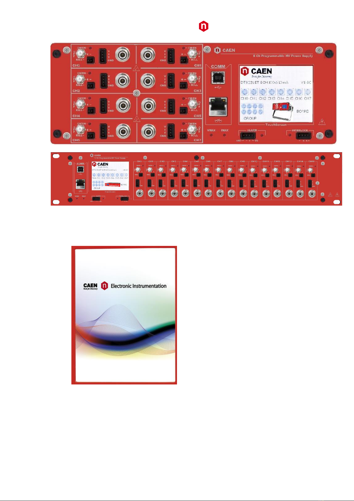
Front panel ...............................................................................................................................................................8
External connections ................................................................................................................................................9
Local control section ..............................................................................................................................................................9
Channel control section .......................................................................................................................................................10
HV Status control section.....................................................................................................................................................10
Alarm signal ...............................................................................................................................................................................10
Interlock signal...........................................................................................................................................................................10
Remote communication control section..............................................................................................................................11
HV Channel Output ..............................................................................................................................................................11
AC Input (DT803x, R803x) ....................................................................................................................................................11
Technical specifications table ................................................................................................................................. 12
4. Operating modes..............................................................................................................13
Hardware installation ............................................................................................................................................. 13
Unit Power ON........................................................................................................................................................13
Local Control........................................................................................................................................................... 14
BOARD Settings....................................................................................................................................................................14
Channel settings...................................................................................................................................................................15
Group Settings .....................................................................................................................................................................16
Status Icon............................................................................................................................................................................18
Remote Control ...................................................................................................................................................... 19
Software tools......................................................................................................................................................................19
GECO2020..................................................................................................................................................................................19
CAEN HV Wrapper .....................................................................................................................................................................19
Power Supply Modules LabVIEW Instrument Driver .................................................................................................................19
PC connection ......................................................................................................................................................................19
Module access via VT emulator ...........................................................................................................................................20
Ethernet Settings .......................................................................................................................................................................20
Format EEPROM ........................................................................................................................................................................21
Channels settings.......................................................................................................................................................................21
Voltage Temperature Compensation (VTC)............................................................................................................ 23
Communication Protocol........................................................................................................................................24
Command interface .............................................................................................................................................................24
Response to command.........................................................................................................................................................24
Command "PARLIST"............................................................................................................................................................24
Command "PARCHLIST" .......................................................................................................................................................24
Parameter descriptor...........................................................................................................................................................25
INFO Commands ..................................................................................................................................................................25
Board Parameters ................................................................................................................................................................25
Channel Parameters.............................................................................................................................................................26
EPICS Service...........................................................................................................................................................26
5. Instructions for Cleaning...................................................................................................27
Cleaning the Touchscreen ...................................................................................................................................... 27
Cleaning the air vents .............................................................................................................................................27
General cleaning safety precautions ......................................................................................................................27
6. Device decommissioning ..................................................................................................28

CAEN
Electronic Instrumentation
803x Series 8-16 Ch. Programmable HV Power Supplies
4
1. Safety Notices
N.B. Read carefully the “Precautions for Handling, Storage and Installation” document
provided with the product before starting any operation.
The following HAZARD SYMBOLS may be reported on the unit:
Caution, refer to product manual
Caution, risk of electrical shock
Protective conductor terminal
Earth (Ground) Terminal
Alternating Current
Three-Phase Alternating Current
The following symbol may be reported in the present manual:
General warning statement
The symbol could be followed by the following terms:
•DANGER: indicates a hazardous situation which, if not avoided, will result in serious injury or death.
•WARNING: indicates a hazardous situation which, if not avoided, could result in death or serious injury.
•CAUTION: indicates a situation or condition that, if not avoided, could cause physical injury or damage the
product and / or its environment.
CAUTION: To avoid potential hazards
USE THE PRODUCT ONLY AS SPECIFIED.
ONLY QUALIFIED PERSONNEL SHOULD PERFORM SERVICE PROCEDURES
CAUTION: Avoid Electric Overload

CAEN
Electronic Instrumentation
803x Series 8-16 Ch. Programmable HV Power Supplies
5
TO AVOID ELECTRIC SHOCK OR FIRE HAZARD, DO NOT POWER A LOAD
OUTSIDE OF ITS SPECIFIED RANGE
CAUTION: Avoid Electric Shock
TO AVOID INJURY OR LOSS OF LIFE, DO NOT CONNECT OR DISCONNECT
CABLES WHILE THEY ARE CONNECTED TO A VOLTAGE SOURCE
CAUTION: Do Not Operate without Covers
TO AVOID ELECTRIC SHOCK OR FIRE HAZARD, DO NOT OPERATE THIS
PRODUCT WITH COVERS OR PANELS REMOVED
CAUTION: Do Not Operate in Wet/Damp Conditions
TO AVOID ELECTRIC SHOCK, DO NOT OPERATE THIS PRODUCT IN WET
OR DAMP CONDITIONS
CAUTION: Do Not Operate in an Explosive Atmosphere
TO AVOID INJURY OR FIRE HAZARD, DO NOT OPERATE THIS PRODUCT
IN AN EXPLOSIVE ATMOSPHERE
THIS DEVICE SHOULD BE INSTALLED AND USED BY SKILLED TECHNICIAN
ONLY OR UNDER HIS SUPERVISION
DO NOT OPERATE WITH SUSPECTED FAILURES.
IF YOU SUSPECT THIS PRODUCT TO BE DAMAGED, PLEASE CONTACT
THE TECHNICAL SUPPORT

CAEN
Electronic Instrumentation
803x Series 8-16 Ch. Programmable HV Power Supplies
6
2. 803x Series Overview
The 803x power supply series provides 8 or 16 independent HV channels, whose control can take place
either locally thanks to a 2.8" Touchscreen Graphic color LCD display or remotely, via USB 2.0 or Ethernet.
The units are available in three formats: double width NIM mechanics, 19” rack module and Desktop case.
NIM and Desktop versions feature 8 channels, the 19” rack units can house either 8 or 16 channels.
5 output ranges are available (100V/10mA, 500V/10mA, 4kV/3mA, 6kV/20µA and 6kV/1mA), with either
positive or negative polarity; all units are provided also in “mixed” version, with half of the channels
positive and half negative. 100V channels are delivered through BNC connectors, other versions feature
SHV’s.
The HV output RAMP-UP and RAMP-DOWN rates may be selected independently for each channel.
Safety features include:
•OVERVOLTAGE and UNDERVOLTAGE warning when the output voltage differs from the
programmed value by more than 2% of set value (minimum 10V).
•Programmable VMAX protection limit via front panel trimmer; common to all channels
•Programmable IMAX protection limit via front panel trimmer; common to all channels
•OVERCURRENT detection: if a channel tries to draw a current larger than its programmed limit,
it enters TRIP status, keeping the maximum allowed value for a programmable time (TRIP),
before being switched off.
•Common Interlock logic for channels enable/disable and individual inputs signal for channel Kill
function.
A complete set of Software Tools is available to control these units; the User can freely download low
level libraries, LabVIEW driver and Graphical application software.

CAEN
Electronic Instrumentation
803x Series 8-16 Ch. Programmable HV Power Supplies
7
3. Technical specifications
Packaging
DT803x: Desktop package (340x110x255mm); Weight: ~5.2kg
N803x: Double width NIM mechanics. Weight ~2.6kg
R803x: 19” rack (h: 2U; d: 400mm). Weight: ~9kg (8 ch), 10.5kg (16 ch)
Power requirements
DT8031
DT8032
DT8033
DT8034
DT8034H
8 Channels
Voltage: 100 -
240V ~
Frequency
50/60Hz
0.8A rms max
Fuse 2xT1A
6.3x32 250VAC
Voltage: 100 -
240V ~
Frequency
50/60Hz
1.6A rms max
Fuse 2xT2A
6.3x32
250VAC
Voltage: 100 -
240V ~
Frequency
50/60Hz
1.6A rms max
Fuse 2xT2A
6.3x32
250VAC
Voltage: 100 -
240V ~
Frequency
50/60Hz
1.6A rms max
Fuse 2xT2A
6.3x32
250VAC
Voltage: 100 -
240V ~
Frequency
50/60Hz
1.6A rms max
Fuse 2xT2A
6.3x32 250VAC
R8031
R8032
R8033
R8034
R8034H
8 Channels
Voltage: 100 -
240V ~
Frequency
50/60Hz
0.8A rms max
Fuse 2xT1A
6.3x32 250VAC
Voltage: 100 -
240V ~
Frequency
50/60Hz
1.6A rms max
Fuse 2xT2A
6.3x32
250VAC
Voltage: 100 -
240V ~
Frequency
50/60Hz
1.6A rms max
Fuse 2 xT2A
6.3x32
250VAC
Voltage: 100 -
240V ~
Frequency
50/60Hz
1.6A rms max
Fuse 2xT2A
6.3x32
250VAC
Voltage: 100 -
240V ~
Frequency
50/60Hz
1.6A rms max
Fuse 2xT2A
6.3x32 250VAC
R8031D
R8032D
R8033D
R8034D
R8034HD
16 Channels
Voltage: 100 -
240V ~
Frequency
50/60Hz
1.6A rms max
Fuse 2xT2A
6.3x32 250VAC
Voltage: 100 -
240V ~
Frequency
50/60Hz
3A rms max
Fuse 2xT4A
6.3x32
250VAC
Voltage: 100 -
240V ~
Frequency
50/60Hz
3A rms max
Fuse 2xT4A
6.3x32
250VAC
Voltage: 100 -
240V ~
Frequency
50/60Hz
3A rms max
Fuse 2xT4A
6.3x32
250VAC
Voltage: 100 -
240V ~
Frequency
50/60Hz
3A rms max
Fuse 2xT4A
6.3x32 250VAC
N8031
N8032
N8033
N8034
N8034H
8 Channels
+6V
2.5A
1A
1A
1A
T.B.D.
-6V
1.6A
500mA
200mA
200mA
T.B.D.
+12V
300mA
2.5A
3.4A
3.4A
T.B.D.
-12V
200mA
2.5A
3.4A
3.4A
T.B.D.

CAEN
Electronic Instrumentation
803x Series 8-16 Ch. Programmable HV Power Supplies
8
Front panel

CAEN
Electronic Instrumentation
803x Series 8-16 Ch. Programmable HV Power Supplies
9
External connections
Local control section
2.8” LED Touch Screen
Parameter and Mode setting; Local settings monitoring

CAEN
Electronic Instrumentation
803x Series 8-16 Ch. Programmable HV Power Supplies
10
Channel control section
HV_EN/OFF/KILL
3 POS. SWITCH
Channel Enable and turning OFF/KILL
ON
RED LED
HV On enabled
REMOTE KILL
AMP 280370-2
The channel is KILLED either as the +/-
contacts are open or as a +4÷6Vdc voltage is
fed to “pin +”, with “pin –“ to GND (Channel
turned off at fastest available rate)
HV Status control section
ALARM
RED LED AMP 280371-2.
Out
Alarm status signalled (active LOW)
INTERLOCK
RED LED AMP 280371-2
In
Interlock signal
VMAX
trimmer
it allows to adjust the hardware maximum voltage VMAX common to
all the channels. Its value can be read out via software.
IMAX
trimmer
it allows to adjust the hardware maximum current IMAX common to
all the channels. Its value can be read out via software.
Alarm signal
As an Alarm condition is detected, pins 2 and 3 (- and +) are closed; the contact can be
used to switch an external device supplied by an external source, otherwise the VB and
GND references can be used to provide a TTL compatible level on pin 2 and 3.
In the first case (externally supplied device) the maximum allowed ratings are:
•Maximum voltage between + and -: 12V
•Maximum sink current across + and -: 100mA
In the latter case, to produce a TTL compatible Alarm Out, pin 3 (+) must be
connected with pin 4 (VB) and pin 1 (GND) with pin 2 (-); see the diagram:
Interlock signal
A schematic diagram of the Interlock input is shown in the figure on the
left, where the diode is part of opto-coupler stage.
Interlock means that channels are hardware disabled. The following table
explains the interlock operation:
CONFIGURATION
INTERLOCK MODE →
UNDRIVEN
DRIVEN
leave contact open
INTERLOCK
ENABLED
voltage level (0÷1V, ~5mA current) between pin 2 (high) and pin 3 (low)
INTERLOCK
ENABLED
short circuit pin 1 with pin 2, and pin 3 with pin 4
ENABLED
INTERLOCK
voltage level (4÷6V, ~5mA current) between pin 2 (high) and pin 3 (low)
ENABLED
INTERLOCK
The front panel Interlock LED is ON when the INTERLOCK is active; as INTERLOCK is active, channels are turned off at the fastest
available rate, regardless the RAMP DOWN setting. To reset the Interlock flag, all switches must be placed on KILL and then on OFF.

CAEN
Electronic Instrumentation
803x Series 8-16 Ch. Programmable HV Power Supplies
11
Remote communication control section
USB B TYPE USB USB2.0 compliant
ETH 10/100 Base-T female connector
HV Channel Output
Channel Output: 8031 series: BNC RADIALL R141.557.000
Electrical: Impedance 50Ω; Operating temp. -65/+165°C;
Frequency 0-4 GHz; VSWR 1.06+0.006 xF(GHz) Max; Insertion loss
.025*√F(GHz) dB Max; RF leakage –(57 - F(GHz)) dB Max; Voltage
rating 500Veff Max ; Dielectric withstanding voltage 1500Veff
min; Insulation resistance 5000MΩ min;
Mechanical: Center contact retention: Axial force –Mating end
18 N min; Axial force –Opposite end 18N min; Torque 2.8 N.cm
min Recommended torque: Panel nut 250 N.cm; Mating life 500
Cycles min Weight 8.000 g
Channel Output: 8032-33-34-34H series: SHV RADIALL R317580;
Impedance: 50 Ohm; Frequency range: 0 –
2 GHz; VSWR: <1.20 + 0.3 F (GHz) –(plug and jack); Test voltage:
10kV DC –1mn (unmated
connectors); Ratings: 12kV DC –1mn (mated pairs); Current
rating: 10 A
MON AMP 280371-2; The test points allow to monitor the
Channel Output Voltage, Current and Temperature.
V/I analog monitor output; range: 0 ÷ +5V; proportional to output
voltage and current.
T: input for PT1000 temperature probe (8031 series only).
WARNING! These connectors produce extremely hazardous high voltages at a potentially lethal
current level; never connect or disconnect the HV OUT connector with the power ON/OFF
switch ON; always switch power OFF and wait at least 30s before connecting or disconnecting
HV cables.
AC Input (DT803x, R803x)
IEC 60 320 Socket with switch; to be connected to Mains 100 - 240 Vac (50 - 60 Hz) via provided power
cord.
Two Fuses: 6.3x32 (8 channels: 1A; 16 channels: 2A); Retarded 250VAC

CAEN
Electronic Instrumentation
803x Series 8-16 Ch. Programmable HV Power Supplies
12
Technical specifications table
1
Series
8031
8032
8033
8034
8034H
Polarity
Positive / Negative / Mixed2depending on purchased version; common ground
Output connector
BNC
SHV
Output Voltage
0÷100 V
0÷500 V
0÷4 kV
0÷6 kV
Max. Output Current
10 mA
10mA
3 mA
1 mA
20 µA
Max. Output Power
1 W
5 W
6 W
0.12 W
Voltage Set Resolution
500µV
2mV
10mV
20mV
Voltage Monitor Resolution
500µV
2mV
10mV
20mV
ISet Resolution
50nA
10nA
5nA
100pA
IMon
Resolution
High range
50nA
10nA
5nA
100pA
Low range
5nA
1nA
500pA
10pA
Ramp Up/Down
1÷50 V/s, 1 V/s step
1÷100 V/s, 1 V/s step
1÷500 V/s, 1 V/s step
VMAX hardware
0÷100 V
0÷500 V
0÷4 kV
0÷6 kV
VMAX hardware resolution
1 V
2V
IMAX hardware
0÷10 mA
0÷3 mA
0÷1 mA
0÷20 µA
IMAX hardware resolution
10µA
1µA
20nA
Alarm output
Open collector, 100 mA maximum sink current
Interlock input
LOW: <1V; current~5mA; HIGH: 4÷6 V
Trip
Max. time an "overcurrent" can last (seconds). A channel in "overcurrent" works as a current generator;
output voltage varies to keep the output current lower than the programmed value. "Overcurrent" lasting
more than set value (1 to 9999) causes the channel to "trip". Output voltage will drop to zero either at the
Ramp-down rate or at the fastest available rate, depending on Power Down setting; in both cases the
channel is put in the off state. If trip= INFINITE, "overcurrent" lasts indefinitely. TRIP range: 0 ÷ 999.9s;
1000 s = Infinite. Step = 0.1 s
Voltage Ripple
10Hz ÷ 1kHz
Typ
3 mVpp
5 mVpp
4 mVpp
Max
5 mVpp
7 mVpp
8 mVpp
1kHz ÷ 20MHz
Typ
1 mVpp
3 mVpp
2 mVpp
Max
3 mVpp
5 mVpp
5 mVpp
Accuracy
Vmon vs. Vout
± 0.02% ± 20mV
± 0.02% ± 100mV
± 0.02% ± 1V
Vset Vs. Vout
± 0.02% ± 20mV
± 0.02% ± 100mV
± 0.02% ± 1V
Imon vs. Iout
High range
± 0.5% ± 50µA
± 0.2% ± 2µA
± 0.2% ± 1µA
± 0.2% ± 20nA
Low range
± 0.5% ± 5µA
± 0.2% ± 200nA
± 0.2% ± 100nA
± 0.2% ± 2nA
Iset vs. Iout
High range
± 0.5% ± 50µA
± 0.2% ± 2µA
± 0.2% ± 1µA
± 0.2% ± 20nA
Low range
± 0.5% ± 5µA
± 0.2% ± 200nA
± 0.2% ± 100nA
± 0.2% ± 2nA
Humidity range
0 ÷ 80% non condensing
Operating temperature
0 ÷ 45°C
Storage temperature
-10 ÷ 70°C
Altitude
≤ 2000m above sea level
Vout / Temperature coeff.
±10 ppm/°C typ
±50 ppm/°C typ
Stability (24h; 1 hour warm up)
±0.01% / full scale
±0.02% / full scale
±0.01% / full scale
±0.01% / full scale
Long Term stability (1 week; 1h warmup)
±0.02% / full scale
±0.04% / full scale
±0.02% / full scale
±0.02% / full scale
Safety Standard – ROHS – Halogen free
RoHS compliant
EMC qualification
CEI EN 61326
1
Validity range of specifications: 8031: 1% to 100%; 8032: 5% to 100%; 8033: 1% to 100%; 8034, 8034H: 5% to 100%
2
Mixed boards have half of the channels with positive polarity and half with negative

CAEN
Electronic Instrumentation
803x Series 8-16 Ch. Programmable HV Power Supplies
13
4. Operating modes
Hardware installation
Prior to shipment this unit was inspected and found free of mechanical or electrical defects. Upon
unpacking of the unit, inspect for any damage, which may have occurred in transport. The inspection
should confirm that there is no exterior damage to the unit, such as broken knobs or connectors, and that
the panels are not scratched or cracked. Keep all packing material until the inspection has been
completed. If damage is detected, file a claim with carrier immediately and notify CAEN. Before installing
the unit, make sure you have read thoroughly the safety rules and installation requirements, then place
the package content onto your bench; you shall find the following parts:
N803x, DT803x or R803x power supply unit
USB cable
10BASE-T Ethernet cable
Power cord (DT803x and R803x only)
N803x’s are housed in a 2-unit NIM mechanics. The unit is an equipment for BUILDING-IN: install it in a
NIM crate providing the required power supplies, with forced cooling air flow, then connect the HV
Channel Output to the load
R803x’s are housed in 19” rack package. The unit is an equipment for BUILDING-IN: install it in a 19” EIA
compliant equipment rack. Use the front panel rack-mount brackets to install the unit in the rack, using
standard screws; leave at least one rack unit of free space above and below the unit. Plug the power cord
into the AC Input (see p.11) and then to the mains AC; connect the HV Channel Output to the load.
D803x’s are housed in a Desktop package. The unit is an equipment for BUILDING-IN: use it on flat solid
surfaces, such as a table or a desk. Plug the power cord into the AC Input (see p.11) and then to the mains
AC; connect the HV Channel Output to the load.
Unit control can take place either locally, assisted by a 2.8" Touchscreen LCD or remotely, via USB, or
Ethernet.
Unit Power ON
−N803x: after hardware installation (see above), turn on the NIM crate
−DT803x, R803x: after hardware installation (see above), turn on the module, via the rear panel
ON/OFF switch

CAEN
Electronic Instrumentation
803x Series 8-16 Ch. Programmable HV Power Supplies
14
Local Control
At power ON the Display shows the Main Menu:
At this point the module is ready to be operated locally. Tap on:
•BOARD icon to access BOARD parameters
•CHx icon to access CHANNELS parameters
•GROUP icon to access CHANNEL GROUP parameters
BOARD Settings
Board Parameters
Status
√
HVMax
HIMax
Interlock
Driven/Undriven
Control
Remote/Local
←
General board parameters (CONTROL can be operated both in LOCAL and REMOTE mode; other settings
are allowed in LOCAL mode only; monitor values are available also with remote control) include:
Parameter:
Type:
Function:
Status
Monitor
Module power supply status
HVMax
Monitor
Hardware Max Voltage settable via trimmer, see p.10
HIMax
Monitor
Hardware Max Current settable via trimmer, see p.10
INTERLOCK
Monitor/Set
Undriven / Driven OPERATION (see p.10)
CONTROL
Monitor/Set
REMOTE: the module is controlled remotely; local monitor is
allowed; LOCAL/REMOTE switch is enabled
LOCAL: the module is controlled locally; remote monitor is allowed
To set one parameter, set Control to “Local”, then tap on the relevant name, and change and/or enter the
desired value; confirm with “Enter”. Tap the red arrow to go back to Main Menu.
CAEN
Tools for Discovery
N8033 8 CH 4KV/3mA
CH0
GROUP
CH1
CH2
CH3
CH4
BOARD
CH5
CH6
CH7

CAEN
Electronic Instrumentation
803x Series 8-16 Ch. Programmable HV Power Supplies
15
Ethernet Configuration: “Network” Icon in the Board settings allows to access Ethernet configuration
menu
<
Ethernet Menu
>
IP Address
192.168.0.250
Mask
255.255.255.000
Gateway
0.0.0.0
√
This option allows to configure the Ethernet settings; once they are done, tap the flag button, but changes
will only become effective at the next power ON. Tap the left arrow to go back.
The right arrow allows to access to DHCP settings:
MAC Address
>
00.12.5e.00.07.07
DHCP
Enabled
√
If a DHCP Server is available, then the module can be enabled or disabled as DHCP client; tap Flag button
to save the new setting and go back to Main Menu: the DHCP server will automatically assign a new IP to
the module at next Power On. Tap the right arrow to go back without changes.
Channel settings
These settings are performed on individual channels:
(±) CH1 MENU ←
(±) CH1 MENU ←
VMon
RampUp
IMon
RampDown
Status
Trip
VSet
PowerDown
ISet
IMonRange
Chan
1/2
Chan
2/3
(±) CH1 MENU ←
VTC
Dis/En
KT
V/°C
T Step
T Ref
T Ext
Chan
3/3

CAEN
Electronic Instrumentation
803x Series 8-16 Ch. Programmable HV Power Supplies
16
N.B. parameters written in italic are available only on x8031 series.
For each channel the following parameters can be programmed and monitored either locally or remotely:
Parameter:
Function:
Unit:
(±)
Channel polarity
Vmon
High Voltage Monitored value
Volt
Imon
Current Monitored value
µA
Status
ON/OFF; Ramp UP/DOWN; OVV; UNV; OVC; OVP; MAXV; TRIP;
OVT; OFF; KILL; ILK; CAL_ERR
Vset
High Voltage programmed value
Volt
Iset
Current Limit programmed value
µA
MaxV
Absolute maximum High Voltage level that the channel can reach
(see p. 12)
V
Ramp-Up
Maximum High Voltage increase rate
V/s
Ramp-Down
Maximum High Voltage decrease rate
V/s
Power Down
Power Down mode after channel TRIP
KILL or RAMP
Trip
Max time "overcurrent" allowed to last (1000= ∞)
s
Imon Range
Current Monitor Zoom
H or L
Parameters available only with x8031 series:
VTC
Enable Temperature compensation
KT
Coefficient of Temperature compensation
V/°C
T Ref
Reference Temperature
°C
T Step
Programmed Interval of Temperature compensation
°C
T Ext
External Temperature
°C
To set one parameter, tap on the relevant name, and change and/or enter the desired value through the
“virtual keypad” (see below); confirm with “Enter”. Tap the red arrow to go back to Main Menu.
1
2
3
4
5
6
7
8
9
.
0
Del
Enter
Group Settings
This menu allows to extend settings to all the channels of the unit, and to monitor all of them.
GROUP MENU
←
Ch
0(-)
1(-)
2(-)
3(-)
VMon
IMon
Status
VSet
Zoom
ISet
Chan
Page
1/3

CAEN
Electronic Instrumentation
803x Series 8-16 Ch. Programmable HV Power Supplies
17
Options available:
Zoom: zoom on voltage and current monitor
Page: access to Channel 4 ÷ 7; 8 ÷ 11; 12 ÷ 15 (depending on number of channels present)
1/3: access to Group parameters:
GROUP MENU ←
MaxV
RampUp
RampDown
Trip
RampDown
PowerDown
IMonRange
Chan
2/3
GROUP MENU ←
VTC
Dis/En
KT
V/°C
T Step
T Ref
T Ext
Chan
3/3
For the Group of all channels, the following parameters can be programmed and monitored either locally
or remotely:
Parameter:
Function:
Unit:
Vmon
High Voltage Monitored value single channels
Volt
Imon
Current Monitored value single channels
µA
Status
ON/OFF; Ramp UP/DOWN; OVV; UNV; OVC; OVP; MAXV; TRIP; OVT; OFF; KILL; ILK;
CAL_ERR single channels
Vset
High Voltage programmed value
Volt
Iset
Current Limit programmed value
µA
MaxV
Absolute maximum High Voltage level that the channel can reach
V
Ramp-Up
Maximum High Voltage increase rate
V/s
Ramp-Down
Maximum High Voltage decrease rate
V/s
Power Down
Power Down mode after channel TRIP
KILL or RAMP
Trip
Maximum time an “overcurrent" can last
s
Imon Range
Current Monitor Zoom
H or L
Parameters available only with x8031 series:
VTC
Enable Temperature compensation
KT
Coefficient of Temperature compensation
V/°C
T Ref
Reference Temperature
°C
T Step
Programmed Interval of Temperature compensation
°C
T Ext
External Temperature
°C
To set one parameter, tap on the relevant name, and change and/or enter the desired value through the
“virtual keypad”; confirm with “Enter”. Tap the red arrow to go back to Main Menu.

CAEN
Electronic Instrumentation
803x Series 8-16 Ch. Programmable HV Power Supplies
18
Status Icon
Three types of Icon in the display status area indicate:
√
OK status
!
WARNING status
!
ALARM status

CAEN
Electronic Instrumentation
803x Series 8-16 Ch. Programmable HV Power Supplies
19
Remote Control
Module control can take place remotely, via USB or Ethernet; an external PC is required (supported OS:
Windows 7 or later; Linux kernel Rel. 2.4 or later). The connection can be performed via VT emulators
(such as Tera Term), or via one of the available tools (see below). The 803x Power Supplies family is
identified as SMART HV by the available software tools. Control option on the Touchscreen must be set
to REMOTE.
Software tools
GECO2020
CAEN GECO2020 is a graphical application that allows to control the 803x Power Supplies (and all other
CAEN Power Supplies). Once the unit is correctly installed, download and install the GECO2020 software
package related to your OS; follow the instructions in the GECO2020 User manual and the unit will be
ready to be operated. For more info, please visit www.caen.it (products>firmware/software section).
CAEN HV Wrapper
CAEN HV Wrapper is a library, available either as a set of ANSI C functions or LabVIEW™VI’s. Such set
provides the software developer a unified software interface for the control of CAEN Power Supplies. This
is a low-level application in which the writing of the Control SW is assigned to the user. It contains a generic
software interface independent by the Power Supply models and by the communication path used to
exchange data with them.
CAEN HV Wrapper is logically located between a higher-level application, such as GECO2020, and the
lower layer software libraries. For more info, please visit www.caen.it (products>firmware/software
section).
Power Supply Modules LabVIEW Instrument Driver
Power Supply Modules LabVIEW Instrument Driver is a set of VI’S, developed for LabVIEW 2017 and later
releases (LabVIEW™is a Trademark of National Instruments Corp.), that allow to configure and monitor
all parameters of remotely controlled CAEN Programmable HV Power Supply modules. Host PC shall run
LabVIEW 2017 or later releases and NI-VISA Run-Time Engine 17.
To install the Power Supply Modules LabVIEW Instrument Driver, go to CAEN web site in the “Software”
area, download the Power Supply Modules LabVIEW Instrument Driver installation package and follow
the Set Up instructions.
PC connection
USB installation
Install the unit, as explained at p. 13
Connect the Unit to the PC via the USB cable
Turn ON the unit via the rear panel (R803x and
DT803x) or NIM bin (N803x) switch
Download and install the USB driver for your OS,
available at the Unit page on the www.caen.it
site3
Now the Unit is ready for operation, upon
installation of one of the available software tools
Ethernet installation
Install the unit, as explained at p. 13
Connect the Ethernet port of the unit to the
relevant port of the PC, using the 10BASE-T
Ethernet cable
Turn ON the unit via the rear panel (R803x and
DT803x) or NIM bin (N803x) switch
Now the unit is ready for operation, upon
installation of one of the available software tools
3
Linux OS Users: the Unit is automatically recognised by Kernel Linux 2.6.9 and higher; unit name is assigned to serial
port with name /dev/ttyACM[x], where [x] is device number; for example 1st module connected is /dev/ttyACM0, 2nd
module is /dev/ttyACM1 etc.

CAEN
Electronic Instrumentation
803x Series 8-16 Ch. Programmable HV Power Supplies
20
Module access via VT emulator
The connection can be performed via VT emulators; we suggest using Tera Term
(see https://ttssh2.osdn.jp/index.html.en)
USB
Launch the terminal emulator, select the serial
communication link and set the virtual
communication port associated to the module.
Select USB connection and the used port
number; set port as follows
baud rate 9600
Data bits: 8
Parity: none
stop bit: 1
Flow control: none
Launch communication
Type caen then <enter>;
Ethernet
Launch the terminal emulator, select port number
1470
Please note that line editing must be disabled prior
to Ethernet access (EnableLineMode=off in the
Teraterm.ini configuration file).
Default settings are:
IP address 192.168.0.250
Subnet mask 255.255.255.0
Gateway 0.0.0.0
Launch communication
Type caen then <enter>;
as the communication is established, the Terminal Board Menu will be displayed:
Ethernet Settings
N.B.: Ethernet settings can be updated ONLY with USB connection; type E on the Board menu: the
following screen will open:
Type S to save; the Ethernet Port is now ready to work with the new settings.
Table of contents
Other Caen Power Supply manuals

Caen
Caen A1536 User manual

Caen
Caen NIM8304 Technical document

Caen
Caen A7030 User manual

Caen
Caen A7502 User manual

Caen
Caen SY 1527 Technical document

Caen
Caen EASY3000 Technical document

Caen
Caen N1471 Series Technical document

Caen
Caen A1539 User manual

Caen
Caen DT5519EN User manual

Caen
Caen A7508 User manual