PAGE 3 OF 4
P E L L M A N H I G H V O LTA G E E L E C T R O N I C C O R P O R AT I O N
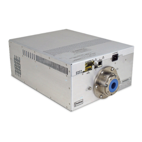
XRV
1.8 6.0KW X RAY
GENERATORS
USA +1 631 630 3000 FAX: +1 631 435 1620
UK +44 (0)1798 877000 FAX: +44 (0)1798 872479
JAPAN +81 (0)48 447 6500 FAX: +81 (0)48 447 6501
CHINA +86 (0)512 67630010 FAX: +86 (0)512 67630030
e mail: sales@spellmanhv.com
www.spellmanhv.com 128060-001 REV.F
Spellman High Voltage is an ISO 9001:2000 and ISO 14001:2004 registered company
RS-232 DIGITAL INTERFACE—
J3 9 PIN FE ALE D CONNECTOR
PIN SIGNAL PARA ETERS
1 NC No Connection
2 TX out Receive Data
3 RX in Transmit Data
4 NC No Connection
5 SGND Ground
6 NC No Connection
7 NC No Connection
8 NC No Connection
9 NC No Connection
J1 HV CONNECTOR—R24/R28
PIN SIGNAL PARA ETERS
C HV Output XRV160 and XRV320—R24 Connector
XRV225 and XRV450—R28 Connector
S Small Filament Output 0 to 6 amps @ 10Vdc
L Large Filament Output 0 to 6 amps @ 10Vdc
J2 ANALOG INTERFACE—25 PIN D CONNECTOR
PIN SIGNAL PARA ETERS
1 Power Supply Fault Low sum of faults HVPS detected a fault
open collector 50V @ 10mA max
2 mA Program 0 to 10V FS Z in = 10M ohms
3 kV Program 0 to 10V FS Z in = 10M ohms
4 Filament Limit L/S Ref.* 0 to 10V FS Z in = 10M ohms
5 Filament Preheat L/S Ref.* 0 to 10V FS Z in = 10M ohms
6 kV Monitor 0 to 10V FS Z out = 4.99k ohms
7 mA Monitor 0 to 10V FS Z out = 4.99k ohms
8 Filament Current Monitor* 0 to 10V FS Z out = 4.99k ohms
9 Signal Ground Ground
10 X-Ray Enable +24Vdc = X-Ray ON connect to pin 14 with
dry contact relay
11 Filament ON* Filament ON status low filament is ON
open collector 50V @ 10mA max
12 Interlock 1 Active low interlock is closed safe to enable HV
13 Interlock 2 Active low interlock is closed safe to enable HV
14 +24Vdc +24Vdc @ 100mA maximum
15 Filament Enable* Active low turn filament ON
16 Filament Control* Active low filament is regulated by ECR (HV must
be ON). Not active the filament is regulated by the
preheat reference
17 Filament L/S Select Filament selection large or small
low = small spot is selected
18 Filament L/S Confirm Open collector 50V @ 10mA max
Filament selection confirm low = small spot is selected
19 HVPS RDY Low = HVPS ready open collector 50V @ 10mA max
20 X-Ray ON X-Ray ON status low = X-Rays are ON
open collector 50V @ 10mA max
21 Interlock Status Low interlocks are closed can enable HV
open collector 50V @ 10mA max
22 GND Digital ground
23 X-Ray ON Pre-Warn Pre-warning low before X-Ray ON
open collector 50V @ 10mA max
24 Reset Active low minimum 10mS transition
25 Arc fault Low arc fault the HVPS has detected an arc
open collector 50V @ 10mA max
ETHERNET DIGITAL INTERFACE—
J4 8 PIN RJ45 CONNECTOR
PIN SIGNAL PARA ETERS
1 TX+ Transmit Data +
2 TX- Transmit Data -
3 RX+ Receive Data +
4 NC No Connection
5 NC No Connection
6 RX- Receive Data -
7 NC No Connection
8 NC No Connection
USB DIGITAL INTERFACE—
J5 4 PIN USB “B” CONNECTOR
PIN SIGNAL PARA ETERS
1 VBUS +5 Vdc
2 D- Data -
3 D+ Data +
4 GND Ground
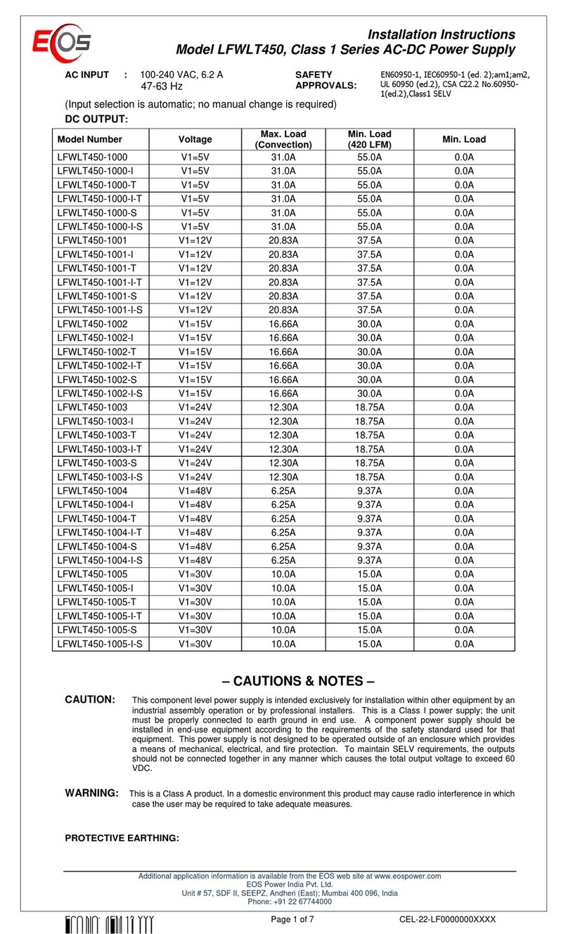
JB1 AIN AND AUXILIARY INPUT POWER—
TYPE 97-3102A-24-11P (Single Phase Units)
PIN SIGNAL PARA ETERS
A Auxiliary AC Line Power 180-264Vac
B Auxiliary Ground Ground
C Auxiliary AC Neutral Neutral
D Main AC Line Power 180-264Vac
E Main Ground Ground
F Main AC Neutral Neutral
*Not active on positive models
ODEL SELECTION TABLE
ODEL VOLTAGE POWER POLARITY
XRV160*1800 160kV 1.8kW Pos or Neg
XRV160*3000 160kV 3.0kW Pos or Neg
XRV160*4000 160kV 4.0kW Pos or Neg
XRV160*6000 160kV 6.0kW Pos or Neg
XRV225*1800 225kV 1.8kW Pos or Neg
XRV225*3000 225kV 3.0kW Pos or Neg
XRV225*4000 225kV 4.0kW Pos or Neg
XRV320P&N1800 ±160kV 1.8kW Bipolar
XRV320P&N4500 ±160kV 4.5kW Bipolar
XRV450P&N1800 ±225kV 1.8kW Bipolar
XRV450P&N4500 ±225kV 4.5kW Bipolar
* pecify P for positive polarity and N for negative polarity. Positive polarity models do not have
integrated filament power supplies. Contact pellman for custom output voltage/power models.
JB1 AIN AC INPUT POWER—
TYPE 97-3102A-24-22P (Three Phase Units)
PIN SIGNAL PARA ETERS
A Line 1 208Vac ±10% 50/60Hz @ 25 amps
B Line 2 208Vac ±10% 50/60Hz @ 25 amps
C Line 3 208Vac ±10% 50/60Hz @ 25 amps
D GND Ground
JB2 AUXILIARY AC INPUT POWER—
TYPE 97-3102A-20-3P (Three Phase Units)
PIN SIGNAL PARA ETERS
A Line 1 208Vac ±10% 50/60Hz (source 3 phase L1 L2)
B Line 2 208Vac ±10% 50/60Hz (source 3 phase L1 L2)
C GND Ground
Note: Use 4 conductor cable or single isolated wires rated no
less that 600Vac, 30 amps (10AWG, minimum)
ystem Ground: ystem ground wires (10AWG minimum) to
the ground terminal E1 GND to the power supply using ground
stud M6 X 20MM, with M6 nut.


