Spelsberg Wallbox Pure User manual
safe.inspiring.green.
PRODUCT MANUAL
Spelsberg Wallbox Pure
Spelsberg Wallbox Smart Pro

2
Inhaltsverzeichnis
1. About this guide.....................................................................4
1.1. Explanation of symbols used......................................................................................................................... 4
2. Safety instructions ...................................................................4
2.1. General safety ................................................................................................................................................ 4
3. Target group ........................................................................5
3.1. Operator/user................................................................................................................................................. 5
3.2. Qualified electrician....................................................................................................................................... 5
3.3. Activities by target group.............................................................................................................................. 5
4. Intended use ........................................................................6
5. What's in the box .... .................................................................6
6. Accessories..........................................................................7
7. Technical description .................................................................7
7.1. Controls and connections.............................................................................................................................. 8
7.2. Type plate....................................................................................................................................................... 8
7.3. Cable entries................................................................................................................................................... 9
8. Storage .............................................................................9
9. Installation.........................................................................10
9.1. Safety............................................................................................................................................................ 10
9.2. Prerequisites................................................................................................................................................. 10
9.3. Preparation for installation......................................................................................................................... 11
9.4. Checking the connectors and the charging cable connection.................................................................. 12
9.5. Installation with wall mounting ................................................................................................................. 12
9.6. Connection of the supply line..................................................................................................................... 14
9.7. Connection of the PV system signal line (optional, Wallbox Smart Pro only) ......................................... 16
9.8. LAN connection setup (optional, Wallbox Smart Pro only)....................................................................... 17
9.9. Essential tests and measurements............................................................................................................... 17
9.9.1. Insulation resistance test ............................................................................................................................. 17
9.10. Initial commissioning................................................................................................................................... 17
9.11. Closing the housing cover ........................................................................................................................... 18
9.12. Fit the design cover...................................................................................................................................... 19
10. Set-up .............................................................................20
10.1. Installing the Spelsberg Wallbox App ........................................................................................................ 20
10.2. Commissioning and configuration of the wallbox via smartphone and NFC by the installer ................ 21
10.2.1. Initial commissioning................................................................................................................................... 21
10.2.2. Reading out existing wallbox data............................................................................................................. 21
10.2.3. Reset to factory settings.............................................................................................................................. 22
10.3. Setting up the wallbox for use by the user/operator ................................................................................ 22
10.4. Setting the charging current....................................................................................................................... 22

3
10.5. Wallbox Smart Pro network setup.............................................................................................................. 23
10.5.1. Network connection via LAN ...................................................................................................................... 23
10.5.2. Network connection via WLAN................................................................................................................... 24
10.6. Configuring applications (Smart Pro only)................................................................................................. 24
10.6.1. Configuring load management .................................................................................................................. 24
10.6.2. Energy management system ....................................................................................................................... 24
10.6.3. OCPP backend .............................................................................................................................................. 25
10.6.4. PV system parameterisation........................................................................................................................ 25
11. Operation ..........................................................................26
11.1. Status LED and buzzer................................................................................................................................. 27
11.2. Charging an electric vehicle ........................................................................................................................ 28
11.3. Ending the charging process....................................................................................................................... 29
11.4. Operation with the app............................................................................................................................... 29
11.4.1. Configuring charging permissions.............................................................................................................. 30
11.4.2. RFID chip programming............................................................................................................................... 30
11.4.3. E-vehicle programming (Plug & Charge/AutoCharge) (Smart Pro only)................................................... 30
11.4.4. Retrieving statistics ...................................................................................................................................... 30
12. Cleaning ...........................................................................31
13. Maintenance .......................................................................31
13.1. Firmware update.......................................................................................................................................... 31
13.1.1. Firmware update (offline)........................................................................................................................... 31
13.1.2. Firmware updates for a networked wallbox (online, Smart Pro only)..................................................... 32
14. Troubleshooting ....................................................................32
14.1. Reading out errors (Spelsberg Wallbox Pure)............................................................................................ 32
14.2. Reading out errors (Wallbox Smart Pro) .................................................................................................... 32
14.3. Emergency release of the charging plug.................................................................................................... 33
15. Repair .............................................................................33
15.1. Safety............................................................................................................................................................ 33
15.2. Contact/Service:............................................................................................................................................ 33
15.3. Original spare parts ..................................................................................................................................... 33
15.4. Replacing the charging cable...................................................................................................................... 33
15.5. Replacing the design cover ......................................................................................................................... 35
15.5.1. Removing the design cover......................................................................................................................... 35
15.6. Replacing the cover retainer....................................................................................................................... 36
16. Warranty...........................................................................36
17. Deinstallation ......................................................................37
18. Disposal ...........................................................................37
19. Technical data ......................................................................37
4
1. About this guide
Read this guide carefully before assembly and operation and keep hold of it. In the event of transfer of the
product pass this guide on to the new user. Further product information, details and technical know-how can
be found on our website.
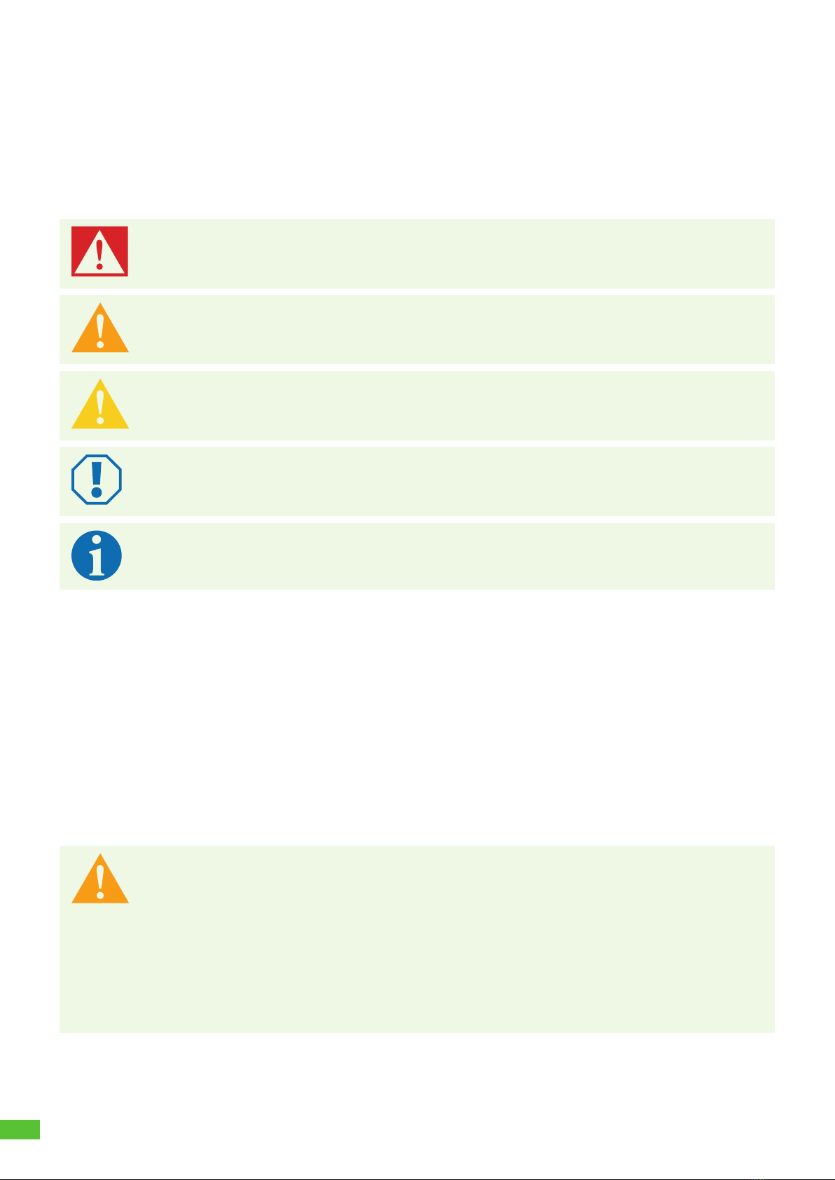
1.1. Explanation of symbols used
Danger
Non-observance will result in death or in serious injury.
►Avoid the danger.
Warning
Non-observance may result in death or in serious injury.
►Avoid the danger.
Caution
Non-observance may result in injury.
►Avoid the danger.
Attention
Non-observance may result in damage to property.
►Avoid damage.
Note
Explanation of Note
Important further information.
2. Safety instructions
The operator is responsible for the proper and safe condition of the wallbox at all times and must check the
wallbox at regular intervals (siehe 13. Wartung, Seite 32).
The manufacturer is not liable for damage resulting from use other than as intended, e.g.:
Assembly or connection errors
Damage to the product from mechanical influences and incorrect connection voltage
Modifications to the product without express permission from the manufacturer
Use for purposes other than those described in the guide
2.1. General safety
Warning
Danger to life from electric shock
►If there is visible damage to the wallbox or the connected cables, remove the wallbox from
operation.
►If the connected cables and lines of the wallbox become damaged, have them replaced by
a qualified specialist company to prevent risks.
►Always pull the charging cable from the vehicle inlet by the plug or the optional connector
holder accessory, never by the cable.
►Never immerse the vehicle charging plug in liquids.

5
Warning
Health hazard
►Do not operate the wallbox at outside temperatures below -30 °C or above +40 °C.
►In case of fire, do not release the wallbox cover. Use extinguishing agents approved for
electronic equipment. Do not use water for extinguishing.
►This appliance can be used by children aged from 8 years and above and persons with
reduced physical, sensory or mental capabilities or lack of experience and knowledge if
they have been given supervision or instruction concerning use of the appliance in a safe
way and understand the hazards involved.
►Children must not play with the appliance.
►Cleaning and operator maintenance must not be carried out by children without
supervision.
3. Target group
3.1. Operator/user
As the operator, you are responsible for the unit. You are responsible for the correct use and safe operation
of the appliance. This also includes the instruction of persons using the device.
As an operator without specialist electrical training, you may only carry out activities that do not require a
qualified electrician.
3.2. Qualified electrician
As a qualified electrician, you have a recognised electrical engineering qualification. Based on this expertise,
you are authorised to carry out the electrotechnical work required in this guide.
Conditions to be met by a qualified electrician:
Knowledge of general and specific safety and accident prevention regulations
Knowledge of the electrotechnical regulations
Knowledge of national regulations
Ability to recognise risks and avoid possible hazards.
3.3. Activities by target group
Operator/user
Operation
Cleaning
Observance of maintenance intervals
Qualified electrician
Installation
Initial commissioning
Maintenance
Troubleshooting/Repair
Decommissioning
6
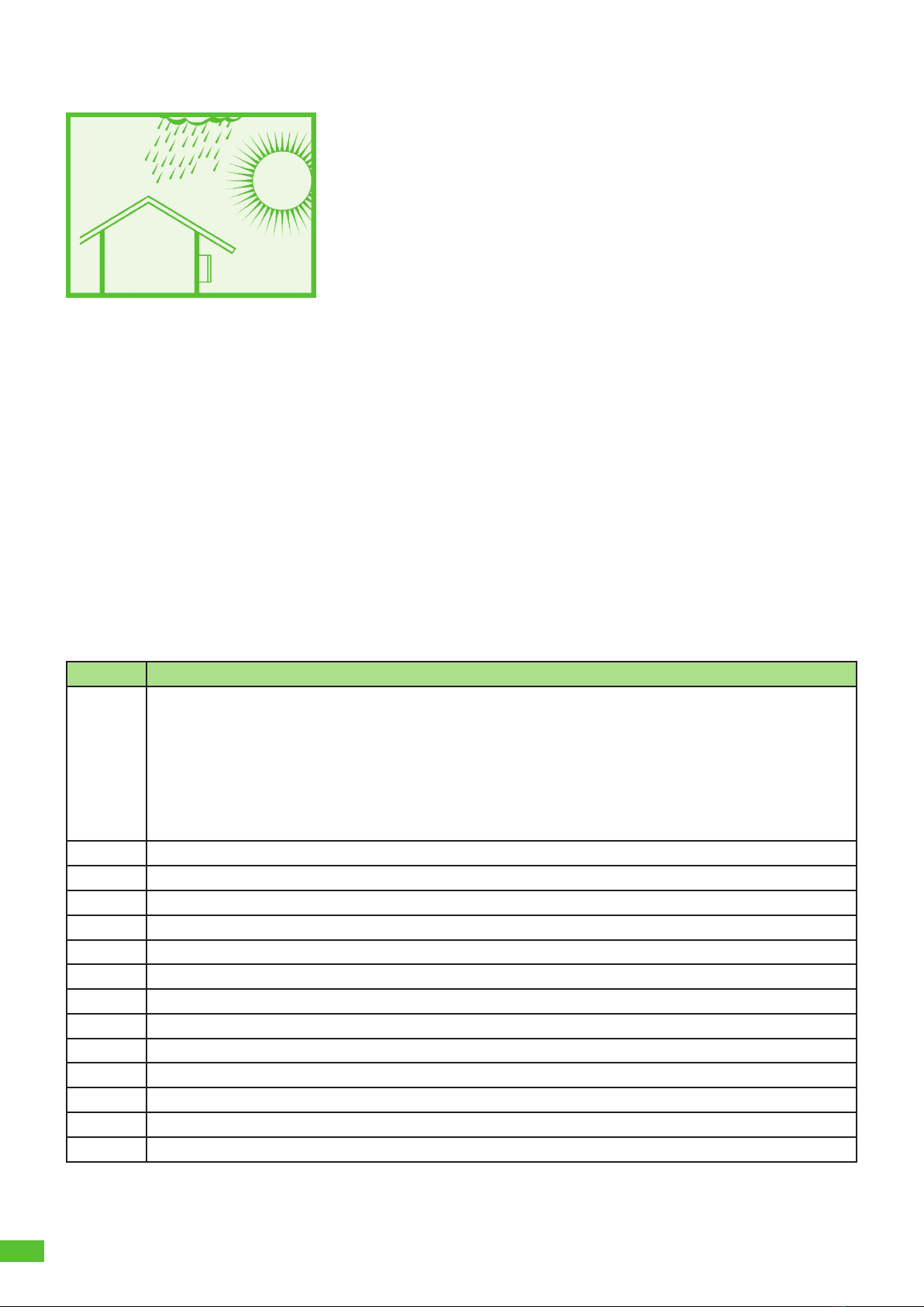
4. Intended use
Abb. 1: Mounting in protected outdoor areas
The wallbox is intended for charging electric vehicles with a Type 2 connector using alternating voltage. The
wallbox is permanently connected to the AC power supply.
The wallbox is suitable for indoor and outdoor use. The wallbox is designed for wall and pedestal mounting.
Only pedestals specified by Spelsberg may be used for pedestal mounting.
The wallbox must be operated in accordance with the applicable international and national regulations.
The following international regulations or respective national implementations must be observed:
IEC 61851-1
IEC 62196-1
IEC 60364-7-722
IEC 61439-7
The wallbox is for use in areas with unrestricted access.
5. What's in the box ....
Quantity Description
1 Wallbox pre-assembled consisting of
Box with integrated cable management
Cover
Cover screws
Cover retainer
Cable entry double membrane seal DMS M25
Strain relief clamp for charging cable
1 Mounting rail
1 Charging cable with Type 2 connector
1 Design cover
5 Chip for unlocking the design cover
3 RFID chip
4 Flat head screw 6x60
4 Universal dowel UX 8 x 50 R
3 Cable entry double membrane seal DMS M16
1 Cable entry double membrane seal DMS M25
1 Cable entry double membrane seal DMS M32
3 Setup QR code for app commissioning
1 Quick Start Guide
1 Installation instructions

7
6. Accessories
Description Order number
RFID chip polar 591 813 01
RFID chip graphite 591 814 01
Single pedestal without roof 591 801 01
Single pedestal with roof 591 802 01
Double pedestal without roof 591 803 01
Double pedestal with roof 591 804 01
Weather-proof cover for wallbox 591 815 01
Connector holder polar 591 807 01
Connector holder graphite 591 808 01
Information on accessories can be found on the Spelsberg website.
7. Technical description
The wallbox provides the AC voltage for single-phase or three-phase charging of electric vehicles (charging
mode 3, Case C connection according to IEC 61851). As soon as the charging cable is connected to the electric
vehicle, the charging process can begin.
Note
State D (ventilation) is not supported.
Depending on the setting in the wallbox, the charging process must first be authorised by the user before
the charging process is started.
After the charging process, the permanently connected charging cable can be stored using the wallbox cable
management system. The protective cap prevents ingress of moisture into the charging connector.
A status LED and a buzzer indicate the state of the wallbox and the charging process.
The wallbox switches off the voltage under the following ambient conditions:
D.C. fault currents > 6 mA
Temperature too high
Overload (Smart Pro only)
Overvoltage/undervoltage (Smart Pro only)
The Spelsberg Wallbox App supports the installer in configuring the wallbox and offers the operator and
user a variety of functions for controlling the wallbox and evaluating the charging processes:
Charging of electric vehicles, provision of AC voltage for this purpose
RFID chip registration
Communication with the vehicle according to ISO 15118 (Plug & Charge), (Wallbox Smart Pro only)
Dynamic load management for operation in a charging network (Wallbox Smart Pro only)
Integration into energy management systems (Wallbox Smart Pro only)
Integration into photovoltaic (PV) charging systems (Wallbox Smart Pro only)
Evaluation of the charging processes (Wallbox Smart Pro only)
The Wallbox Smart Pro can be connected to the Internet through the following options:
LAN (standard)
WLAN

8
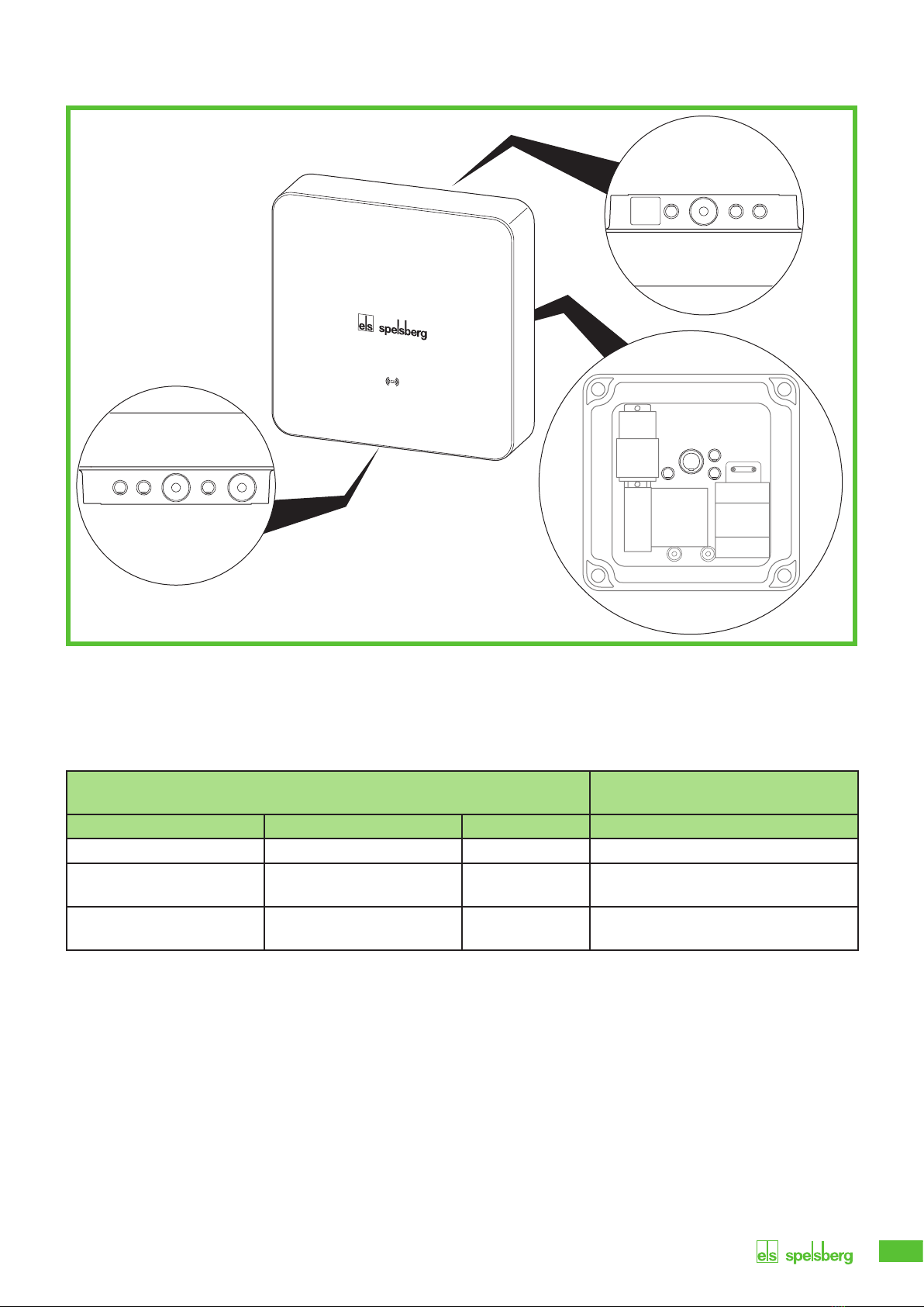
7.1. Controls and connections
Abb. 2: General view
No Description
1Type plate (under the design cover)
2Status LED, buzzer and RFID reader
3Charging cable
4Cable management
7.2. Type plate
Abb. 3: Type plate
No Description
1Wallbox designation
2Technical data
3Protection class
4Manufacturer address
5Serial number
6Product code
4
1
2
3
6
5
1
4
2
3
9
7.3. Cable entries
Abb. 4: Knockouts in the housing
The wallbox has a number of cable entries. The cable entries are suitable for the matching double membrane
seals (DMS). Most of the cable entries are closed at the factory and provided with knockouts for opening
them up.
The following cable entries and knockouts can be found on the wallbox:
Knockouts matching double membrane seal
DMS
top bottom rear Sealing area (size)
3x M16 3x M16 3x M16 5 – 9 mm (M16)
1x M25/32
fitted with DMS M25
1x M25/32
fitted with DMS M25
1x M25/32 9 – 16 mm (M25)/
14 – 21 mm (M32)
1x M25
for the charging cable
9 – 16 mm (M25)
8. Storage
►Store the unit, the charging cable and the accessories in their original packaging in a dry and clean place
until assembly.

10
9. Installation
9.1. Safety
Caution
Risk of injury
The user may suffer injury from damaged components.
►Do not mount the charging station
– near combustible materials.
– in areas with a risk of explosion.
– in salty or wet environments.
– near corrosive fumes.
– in environments subject to constant vibration.
Examples of such environments include outdoor areas of petrol stations, chemical plants,
landfills, and sewage treatment plants.
Attention
Risk of damage from the effects of weather
The charging station may be damaged by an incorrect choice of location.
►Do not expose the charging station to any heat source (e.g. sunlight, heating).
►Mount the charging station in a place that is protected from rain and splash water.
Risk of damage from drilling
Parts of the installation can be damaged by incorrectly performed drilling.
►Before creating drill holes in the wall/mounting surface, make sure that no electrical cables
or other wiring will be damaged by the drilling.
9.2. Prerequisites
The following protective devices must be provided on-site to safeguard the wallbox:
Back-up fuse of max. 16 A. The manufacturer recommends:
• 230 V: Overcurrent switch (C-characteristic); 1-pole
• 400 V: Overcurrent switch (C-characteristic); 3-pole, all-pole switching
Residual current device (RCD) Type A with IΔn≤30 mA
• 230 V: FI circuit breaker 2-pole
• 400 V: FI circuit breaker 4-pole
Depending on installation site: Surge protector according to national and regional regulations.
Take note of the following instructions when selecting the installation location:
Only mount the wallbox vertically (e.g. on building walls).
The mounting surface must be level and have sufficient strength. If there is any unevenness on the wall
of more than 2 mm, equalisation under the fixing points must be provided to avoid distortion of the
housing systems.
The fixing material used must be suitable for the fixing surface.
There must be a clearance of at least 250 mm around the wallbox. This also applies to plant growth.
Spelsberg recommends maintaining sufficient distance from other obstacles in the installation
environment.
The underside of the wallbox must be at least 900 mm above the ground.
The wallbox must always be adequately lit during operation. Install lighting if necessary.

11
You will need the following tools for mounting:
Drill
Screwdriver (suitable for the fastening screws used and the cover screws)
Spirit level
Pencil
Side cutters
Stripping tool
Crimping pliers
9.3. Preparation for installation
Note
Double membrane seals are provided on the top and bottom of the wallbox for the power
supply. Knockouts only need to be pushed through if further cables are to be connected or are
to be inserted into the wallbox from the rear.
If the diameter of the supply line exceeds the sealing range of the pre-installed M25 DMS:
►Remove the pre-fitted M25 DMS.
►Push through the corresponding knockout.
►Fit an M32 DMS.
Abb. 5: Pushing through bottom knockouts
►Only for cable entry through the rear wall: Unscrew the housing cover from the wallbox.
►Push through the necessary knockouts in the housing.
►Fit the respective DMS.
60 − 75°

12
9.4. Checking the connectors and the charging cable connection
Abb. 6: Charge controller connections
No Description No Description
1 Connection plug A (PE, CP, ...) 7 Measuring current transformer connection
2 LAN connection (LAN-2, Smart Pro only) 8 2-phase cut-off connection (Smart Pro only)
3 LAN connection (LAN-1, Smart Pro only) 9 PV enabling contact connection (Smart Pro
only)
4 1x USB type A (HMI board connection),
USB 2
10 Contactor control connection
5 1x USB type A (Smart Pro only), USB 2 11 Supply voltage connection
61x USB type B (service port)
►Check all connectors for tightness.
9.5. Installation with wall mounting
Note
Dowels and screws are included in the scope of delivery.
►Use flat-head screws (no countersunk screws).
To mount the wallbox you will need:
4 screws (maximum diameter 6 mm, minimum screw head diameter Ø 12 mm, maximum Ø 15 mm)
4 matching dowels
Drilling template
1
2
3
4
5
6
11
10
9
8
7
13
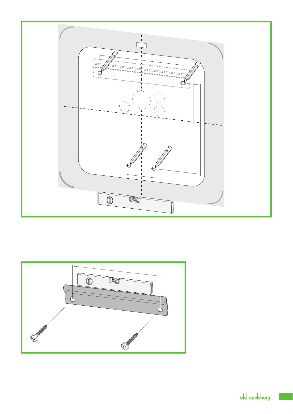
Abb. 7: Mark the fixing points
►Mark the fixing points of the mounting rail and wallbox (Abb. 7).
►Only for cable entry through the rear wall: Mark the respective cable entries of the wallbox (Abb. 7).
►Drill the holes for the fixing points.
►Insert the dowels into the holes.
Abb. 8: Fit the mounting rail
►Screw on the mounting rail.
►Only for cable entry through the rear wall: Lay the necessary cables (e.g. power supply, LAN cable).
►Only for cable entry through the rear wall: Guide the required cables through the respective cable
entries in the rear wall of the wallbox.
Bohrschablone
Drilling Template
M 32
M16
TOP
M2-007-01_082022
M16
M16
150 mm
5,91“
68 mm
2,68“
163 mm
6,42“
45 mm
1,77“
150 mm
14
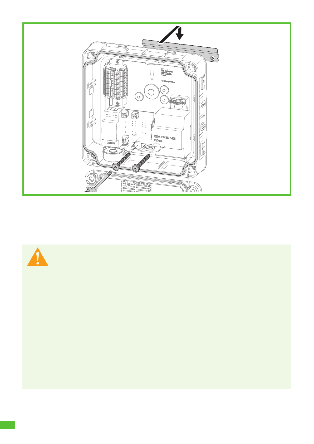
Abb. 9: Mount the wallbox on the wall
►Position the wallbox centrally on the mounting rail (1.).
►Screw the wallbox tight with the 2 screws (2.).
9.6. Connection of the supply line
Warning
Danger to life from electric shock
There is a risk of electric shock due to errors when connecting to the electrical supply line.
►The connection to the electrical supply line must be performed by a locally authorised
electrician only.
►Install a suitable residual-current circuit-breaker and appropriate fuse protection in the
supply line.
►Take note of the following safety rules before any work on electrical components:
– Isolate.
– Secure against re-closing.
– Determine the absence of voltage on all poles.
– Earth and short-circuit.
– Cover or cordon off adjacent live parts.
►Take note of local regulations and laws.
►Before connecting, ensure that the supply line, plugs, and connection sockets are clean and
dry.
►Never touch the plugs if your hands are wet or your feet are standing in the wet.
►When connecting the supply line and the LAN cable , ensure that the cables and lines are
not damaged.
Use a supply line with the maximum cross-section of the connection terminal: rigid and flexible 6mm2,
flexible with wire-end ferrule 4mm2.
1.
2.
15
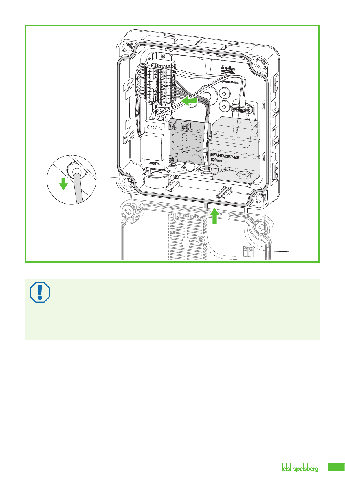
Abb. 10: Connecting the supply line
Attention
Risk of damage to the wallbox
Incorrect wiring may damage the wallbox.
►Ensure a clockwise rotation for a 400 V power supply.
►For a 1-phase wallbox connection, always connect the 230 V power supply to L1.
►If you operate multiple 1-phase connection wallboxes in a charging network, ensure that
the load is distributed evenly over the various phases to avoid imbalances.
►Guide the supply line through the intended DMS.
►Pull back the supply line so that the DMS creates a funnel away from the housing.
►Strip the cores of the supply line to 10 - 12 mm.
3.
1.
2.
16
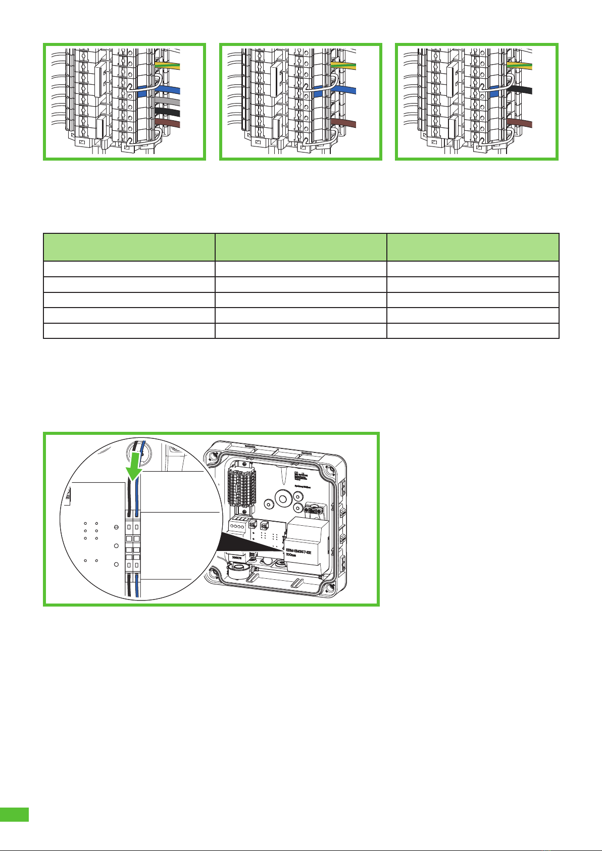
Abb. 11: 3-phase connection of
the supply line in the TN/
TT system (400 V)
Abb. 12: 1-phase connection of
the supply line in the TN/
TT system (230 V)
Abb. 13: 2-phase connection of
the supply line in the TN/
TT system (230 V)
►Connect the cores as follows:
3-phase connection in the
TN/TT system (400 V)
1-phase connection in the
TN/TT system (230 V)
2-phase connection in the
TT/IT network (230 V)
L1 - brown L1 - brown L1 - brown
L2 - black – –
L3 - grey – –
N - blue N - blue N - black (L2*)
PE - green/yellow PE - green/yellow PE - green/yellow
*Note: In a TT or IT system with 230 V between the outer conductors and without a neutral conductor, the
wallbox must be installed so that one phase is connected to terminal L1 and the other phase to terminal N.
9.7. Connection of the PV system signal line (optional, Wallbox
Smart Pro only)
Abb. 14: Connecting the PV system control line
A potential-free switching contact (relay, normally open contact) is required to connect a PV enable contact
on the photovoltaic system side. Use an unshielded control line 2 x 0.75mm2.
►Guide the control line through the intended DMS.
►Pull back the control line so that the DMS forms a funnel away from the housing.
►Strip 8 - 10 mm of insulation from the cable.
►Lay the control line to the spring-cage clamps.
PE
L2
L1
L3
L2
PE
L2
L1
PE
L2
L1
PV1 PV2

17
Note
The parameters for using the potential-free contact, e.g. for connecting the inverter of the
photovoltaic system to the wallbox, must be set in the Spelsberg Wallbox App (siehe 10.6.4. PV-
Anlage parametrieren, Seite 25).
9.8. LAN connection setup (optional, Wallbox Smart Pro only)
Attention
Risk of damage to the LAN cable
Excessive kinking of the LAN cable may cause it to be damaged and its function to be limited.
►Note the bending radii of the LAN cable used.
►Guide the LAN cable line through the intended DMS. Use a category 6 or 7 LAN cable (Cat 6 or Cat 7).
►Pull back the LAN cable so that the DMS forms a funnel away from the housing.
►Crimp an RJ45 connector onto the LAN cable.
►Connect the LAN cable to the LAN connection socket LAN-1 in the cover (Abb. 6 No 3).
►Secure the LAN cable to the existing cable harness leading to the cover.
9.9. Essential tests and measurements
Note
A commissioning report template can be found on the Spelsberg website:
www.spelsberg.de/service/support/elektromobilitaet/wallbox/
►Switch on the supply voltage.
►Before initial commissioning, check and record whether the protective measures of the installation
function according to the nationally applicable regulations, including:
• Continuity of the connections of the protective conductor
• Insulation resistance (with disconnected controller and disconnected measuring devices (meters))
• Residual current circuit breaker
• Tripping current
• Trip time
►Pass the test and handover reports to the operator of the system.
9.9.1. Insulation resistance test
►Remove the following plugs and cables within the wallbox:
• Contactor control connection on the charge controller (Abb. 6 No 9)
• Supply voltage connection on the charge controller (Abb. 6 No 10)
• Wallbox Smart Pro only: N line at MID meter (terminal 10)
►Check the insulation resistance.
►Restore the connections.
►Check all connectors for tightness.
9.10. Initial commissioning
►Check the connections.
►Apply the supply voltage by activating the fuse.
►Check the voltage and the rotating field.
►Close the housing cover (siehe 9.11. Gehäusedeckel verschließen, Seite 18)
►Continue with the setup (siehe 10. Einrichtung, Seite 20).
NN

18
9.11. Closing the housing cover
Abb. 15: Closing the housing cover
►Close the housing cover. Ensure that the cables are not pinched.
►Rotate the quick-release fasteners in the housing cover of the wallbox a quarter turn clockwise until you
feel them engage.
►Fit the design cover (siehe 9.12. Designcover montieren, Seite 19).

19
9.12. Fit the design cover
Abb. 16: Fitting the design cover
Note
Ensure that the RFID logo remains clear (no stickers or similar covering it). Otherwise, the NFC
functionality may be restricted.
►Push the design cover onto the wallbox. The Spelsberg logo must be legible (see Abb. 16).
9The design cover snaps into the latching hooks on the side walls of the wallbox.

20
10. Set-up
Note
In the following situations, the wallbox must not to be set up via smartphone:
– 3-phase connection type
– Home connection and supply line designed for 16 A
– Autonomous operation without load management, connection to energy management
systems or PV systems
For documentation and handover, Spelsberg recommends commissioning via smartphone.
Note
Several identical setup QR codes are available for launching the app. These contain sensitive
access data.
►Keep the setup QR codes in a safe place. Affix the setup QR codes to the manual or on the
invoice, for example.
►For example, do not affix the setup QR code to the wallbox where it is visible from the
outside.
10.1. Installing the Spelsberg Wallbox App
For the initial set-up via smartphone the latter must be NFC enabled.
Prerequisites
Android version 6 or higher - API level 23, e.g. Samsung Galaxy A6 or newer
iOS version iOS 13 or higher, e.g. iPhone 7 or newer
►Download the "Spelsberg Wallbox App" from the "Play Store" or "App Store" and install it on your
smartphone. Alternatively, use the following QR code link to retrieve the app:
spelsberg.com/wallbox/app/
Other manuals for Wallbox Pure
1
This manual suits for next models
9
Table of contents
Popular Automobile Batteries Charger manuals by other brands


Juice Technology
Juice Technology JUICE FLOW user manual

EVBox
EVBox Iqon Installation and commissioning manual

Alpitronic
Alpitronic Hypercharger HYC 50 Operation and installation guide

Leviton
Leviton EVB16 user guide

Schumacher Electric
Schumacher Electric SC1402 owner's manual

Free2Move eSolutions
Free2Move eSolutions eProWallbox Move installation manual


