CLEANING Call our Customer Support Hotline at 855-5-PLUG-IN. PLEASE HAVE THE MODEL NUMBER AND
SERIALNUMBERAVAILABLEWHENYOUCALL.Thesecanbefoundonthelabelontheinsidecover
of the Charging Station.
If your call is made after business hours or on weekends, please leave your name, telephone number,
the Charging Station's serial number, and a brief description of the problem. A Customer Service
Representative will call back at the earliest opportunity.
For additional products and information, and for complete step by step guidelines on how to install
our Electric Vehicle Chargers and Pre-Wire Kits, please visit our website for our "How To Install" videos -
www.leviton.com/toyota.
CUSTOMER SUPPORT
Formoreinformationcall855-5-PLUG-INorvisitwww.leviton.com/toyota PK-93979-10-00-0A-X1© 2012 Leviton Mfg. Co., Inc.
FCC INFORMATION
This device complies with part 15 of the FCC rules. Operation is subject to the following two conditions: (1)
This device may not cause harmful interference, and (2) this device must accept any interference received
including interference that may cause undesired operation.
CAUTION: Any changes or modifications not expressly approved by Leviton will void the user’s authority
to operate this equipment.
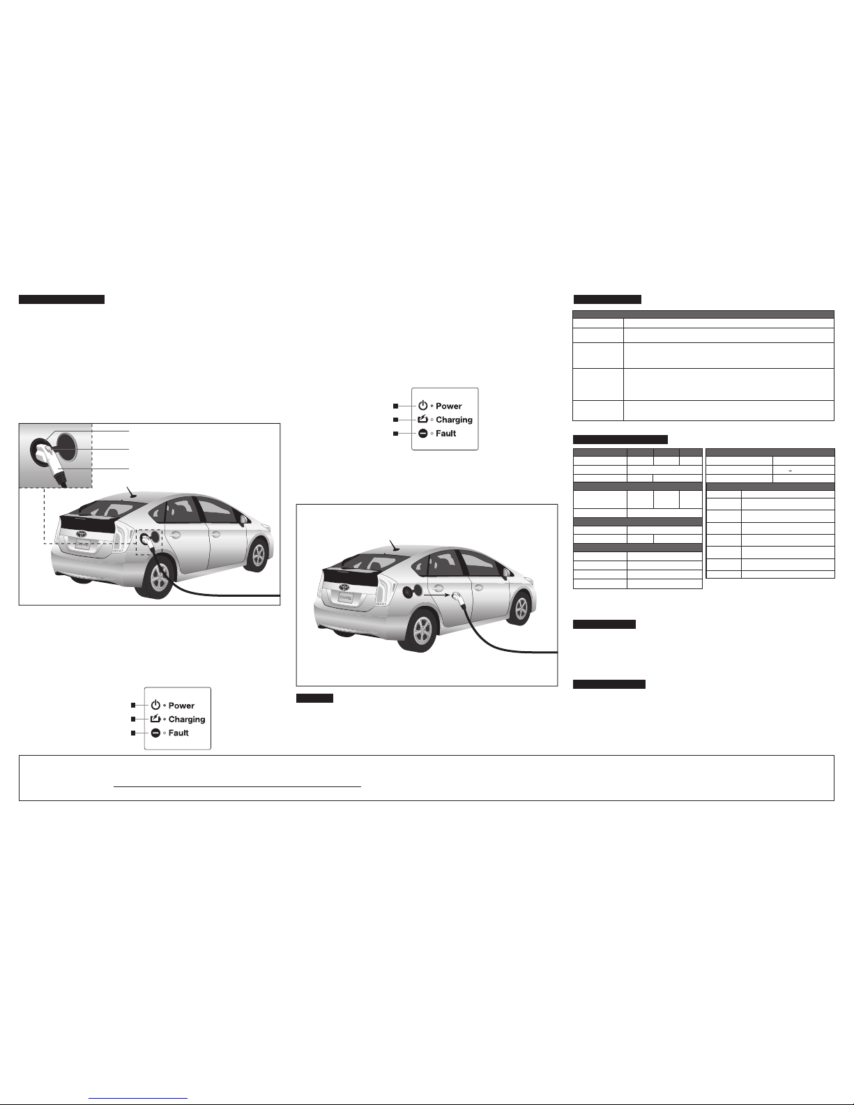
CHARGING YOUR VEHICLE
1. ConnecttheChargingStationtotheVehicle:
NOTE: The vehicle must be parked close enough to the Charging Station to allow the Charge
Connector to connect to the vehicle charge port without putting any stress on the Charge Connector
Cord. Position the Charge Connector Cord so that it will not be stepped on, tripped over or otherwise
subjected to damage or stress.
Plug the Charge Connector of the Charging Station into the charge port on the vehicle
(seevehicleowner’smanualforlocationofchargeport). Ensure that the Charge Connector
is fully engaged, and cannot be removed from the vehicle without depressing the release button.
Once the Charge Connector is engaged, a self-test will initiate, where the Power LED will flash for
approximately 3 seconds. If no fault is detected and a proper connection is made between the vehicle
and the Charging Station, the Power LED will illuminate solid and the Charging LED will start flashing,
indicating charging has begun.
NOTE: The Charge Connector Release Button has to be fully released in order for the charging to
start. The Charge Connector cannot be disengaged from the vehicle charge port without depressing
the Charge Connector Release Button. Pressing the Charge Connector Release Button stops the
charge to the vehicle.
2. Charge Vehicle:
Charging will continue until the battery is fully charged. Verify that the Power LED is illuminated, the
Charging LED is flashing and the Fault LED is off.
NOTE: Disengaging the Charge Connector from the vehicle charge port while charging will
automatically stop the charging process. Reinserting the Charge Connector into the vehicle charge
port will automatically restart charging after a self-test.
In the event of a power outage, all LEDs will turn off. When power resumes, the Charging Station
will enter a Cold Load Pickup mode. This is a random (2-15 min) delay for the self-test start after
which charging will resume. The Power LED will then flash momentarily while performing a self-test.
Charging will resume when the self-test is complete.
3. End Charge:
Once the vehicle has been fully charged, the charging process will automatically stop.Verify that the
Power LED is illuminated, and that the Charging and Fault LEDs are off. The total charge time will
vary based on vehicle, initial charge state of battery, and other variables. Consult your vehicle owner's
manual for specific charge rates. If the vehicle is charging longer than the amount of time specified in
the vehicle owner's manual, disconnect the Charging Station from the vehicle and contact the vehicle
manufacturer.
While in the charging state it may be necessary to stop the charging process. To stop the
charging process, disconnect the Charge Connector from the vehicle charge port. The Charging LED
will turn off to alert the user that the charging process has ceased.
4. DisconnectChargeConnector:
CAUTION: Once the vehicle is fully charged, the Charge Connector must be disconnected from the
vehicle charge port before the vehicle can be moved. Simply depress the Charge Connector Release
Button on the Charge Connector and unplug it from the vehicle charge port.
Carefully loop the Charge Connector Cord around the Charging Station.
Power LED (Green) is ON
Charging LED (Amber) is FLASHING
Fault LED (Red) is OFF
The Charging Station does not require any maintenance other than occasional cleaning.
NOTE: For Plug-In Units - Unplug Charging Station from wall outlet before cleaning.
For Hard-Wire Installation - Turn off the Charging Station at the circuit breaker before cleaning.
Use a soft, lightly moistened cloth with a mild detergent solution. DO NOT use any type of abrasive
pad, scouring powder, or flammable solvents such as alcohol. DO NOT power up Charging Station until
completely dry.
Electrical Input EVB16 EVB30 EVB40
Electrical Output
Material Specifications
Environmental Specifications
Amperage
Voltage
Configuration (NEMA Plug)
Power
Charging Connector
Enclosure
16A 30A 40A
120/208VAC or 120/240VAC
6-20P 6-50P
3.8kW
(16A @
240VAC)
7.2kW
(30A @
240VAC)
9.6kW
(40A @
240VAC)
SAE J1772TM
ValoxTM 357U PBT
Operating Te mperature
Operating Humidity
Electronics Enclosure
-35°C to 50°C
95% non-condensing
Storage Te mperature -50°C to 80°C
NEMA Ty pe 4
Charge Connector Cord
UL Type EVT UL Type EVE
Performance Specifications
Surge Protection
Electromagnetic Compatibility
6kV@ 3000A
FCC Part 15 Class B
Ground Fault Protection 17mA +2.5mA CCID
Standards & Certifications
UL 2251 Standard for Plugs, Receptacles and
Couplers for Electric Vehicles
UL 2231 Standard for Personnel Protection Systems
for Electric Vehicle (EV) Supply Circuits
UL 991 Standard for Tests for Safety-Related
Controls Employing Solid-State Devices
UL 1998 Standard for Software in Progammable
Components
UL 62 Standard for Flexible Cords and Cables
NEC Article 625
Electric Vehicle Charging System Equipment
SAE J1772
TM
Electric Vehicle Conductive Charge Coupler
Standard
J1772 is a trademark of SAE International
UL 2594 Outline of Investigation for Electric Vehicle
Supply Equipment
TECHNICAL SPECIFICATIONS
TROUBLESHOOTING
No power;
no LED indicators lit
Check that Charging Station is plugged into receptacle.
Check that circuit breaker(s) is turned on. If LEDs still not lit, Call Customer Support Hotline.
Charging LED
not flashing
Check that Charge Connector is fully engaged. The Release Button should be fully released.
Check that vehicle is not fully charged.
Self diagnostic test failed. Unplug Charge Connector and reconnect.
If LED still not lit, Call Customer Support Hotline.
Fault LED flashing
Wait to ensure self-test is complete. If a fault is detected, the Fault LED will continue to flash,
and the vehicle will not charge. The Charging Station will go into an Auto-Restart every 15
minutes. If no fault is detected after the Auto-Restart, the Fault LED will turn off, the
Charging LED will illuminate, and charging will commence. If the fault is still detected after 3
attempts, the Fault LED will illuminate solid Red. Call Customer Support Hotline.
Fault LED illuminated
solid Red
The Charging Station has been unable to detect a safety ground, or has failed 3 consecutive
self-tests. Disconnect the Portable Charger from the power source, and begin again from step 1.
If the fault continues, call Customer Support Hotline.
PROBLEM
ACTION
TROUBLESHOOTING
Charge Connector
Release Button
Vehicle Charge Port
Power LED (Green) is ON
Charging LED (Amber) is OFF
Fault LED (Red) is OFF
LIMITEDTEN(10)YEARWARRANTYANDEXCLUSIONS
Leviton warrants to the original consumer purchaser and not for the benefit of anyone else that this product at the time of its sale by Leviton is free of defects in materials and workmanship under normal and proper use for ten (10) years from the purchase date for all components other than the charge connector on the EVB16
and EVB30 units. The charge connector on the EVB16 and EVB30 units is covered by a three (3) year limited warranty from Yazaki North America, Inc., to the original consumer. A copy of Yazaki’s three (3) year charge connector warranty may be found at leviton.com/toyota/warranty. Leviton’s only obligation is to correct such
defects by repair or replacement, at its option, if within such ten (10) year period, the product is returned prepaid, with proof of purchase date, and a description of the problem to Leviton Manufacturing Co., Inc., 201 North Service Road, Melville, NY 11747. This warranty excludes and there is disclaimed liability for labor for
removal of this product or reinstallation. This warranty is void if this product is installed improperly by an individual or entity not approved by Leviton, or in an improper environment, overloaded, misused, opened, abused, or altered in any manner, or is not used under normal operating conditions or not in accordance with any labels or instructions. There
are no other or implied warranties of any kind, including merchantability and tness for a particular purpose, but if any implied warranty is required by the applicable jurisdiction, the duration of any such implied warranty, including merchantability and fitness for a particular purpose, is limited to three years. Leviton is not liable for
incidental, indirect, special, or consequential damages, including without limitation, damage to, or loss of use of, any equipment, lost sales or prots or delay or failure to perform this warranty obligation. The remedies provided herein are the exclusive remedies under this warranty, whether based on contract, tort or otherwise.