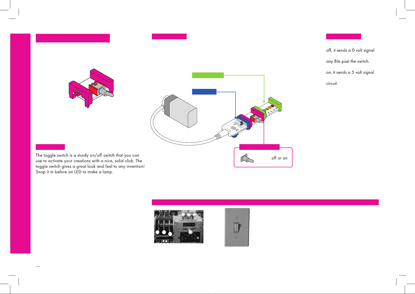
Sphero LittleBits User manual

1
2
5
7
34
59
78
86
88
INTRODUCTION
HOW TO USE LITTLEBITS
BIT INDEX
POWER
INPUT
WIRE
OUTPUT
ACCESSORIES
INVENTION CYCLE
TROUBLESHOOTING
TABLE OF CONTENTS
BIT
INDEX

Occasionally BitsTM and accessories get updated, so the features or

llo!
you want to know about all the Bits in

2
MAKE THIS CIRCUIT FIRST
And play with it!
1
ma some noise a buzzer
HOW TO USE
LITTLEBITS

3
ANATOMY OFA BITTM
2TOP BOTTOM
COLOR-CODED BY FUNCTION
BitsTM
Learn more about your Bits ON PAGE 04
3
POWER (BLUE)
Power Bits, plus a power
supply, run power through
INPUT (PINK)
Input Bits accept input from
OUTPUT (GREEN)
Output Bits do something –
WIRE (ORANGE)
Wire Bits connect to other
systems and let you build
MAGNET MAGIC!
always right – you can’t snap them together the4
ARROWS SHOULD POINT IN THE SAME DIRECTION
IF THE BITS WON’T SNAP TOGETHER, TRY SPINNING
ONE AROUND AND MAKE SURE THE ARROWS POINT
IN THE SAME DIRECTION
ORDER IS IMPORTANT
POWER BITSINPUT BITS
OUTPUT BITS5
WITH NO OUTPUT BIT AFTER IT, THE INPUT BIT HAS NOWHERE
TO SEND ITS SIGNAL
THE INPUT BIT AFFECTS THE OUTPUT BITS THAT FOLLOW
BITSNAP BIT FEET

4
BITTM INDEX
p1 power
p3 USB power
i1 slide switch
i2 toggle switch
i3 button
i5 slide dimmer
i6 dimmer
i7 remote trigger
i11 pressure sensor
i12 temperature
sensor
i13 light sensor
i16 pulse
i17 timeout
i18 motion trigger
i19 roller switch
i20 sound trigger
i21 microphone
i22 sequencer
i23 threshold
i25 MP3 player
i30 keyboard
i31 oscillator
i34 random
i35 delay
i36 micro sequencer
w1 wire
w2 branch
w3 OR
w4 AND
w5 MIDI
w7 fork
w8 latch
w9 proto
w14 Makey Makey®
w15 NOR
w16 NAND
w17 XOR
w18 CV
w19 split
w22 wireless
transmitter
w26 codeBit
w27 USB I/O
w29 perf
w30 littleBits
Bluetooth™Low
Energy Bit
o1 LED
o2 long LED
o3 RGB LED
o6 buzzer
o7 IR LED
o9 bargraph
o13 fan
o14 bright LED
o15 UV LED
o16 light wire
o21 number
o25 DC motor
o26 speaker
a2 USB cable
a5 magnet shoes
a6 hook & loopshoes
a8 brick adapter
a10 motorMate
a14 USB cable & adapter
a21 powerSnap
a23 mechanical arm
a25 wheel
a27 rechargeable battery
a26 mounting board
a28 mounting board
05
06
POWER INPUTWIRE OUTPUTACCESSORIES
07
08
09
10
11
12
13
14
15
16
17
18
19
20
21
22
23
24
25
26
27
28
29
30
31
32
33
34
35
36
37
38
39
40
41
42
43
45
46
47
48
49
59
60
61
62
63
64
65
66
67
68
69
70
71
72
73
74
78
79
80
81
82
83
Occasionally BitsTM get updated, so the features or appearance
51
52
53
55
56
57

5
MEET THE BIT
HOW IT WORKS
p7POWER
The power Bit also sends a
Controlling this signal with
inputs is how you control
REAL WORLD ANALOGIES
PHONE CHARGER
o2 LONG LED
p7 POWER
MODE:
on light
SAMPLE CIRCUIT

6
MEET THE BIT
HOW IT WORKS
p3 USB POWER
The USB power may be the smallest in the series, but it's big
be connected to a computer, the AC power adapter, or the
The USB power Bit sends a
circuit, which allows you to
REAL WORLD ANALOGIES
PHONE CHARGER LAPTOP CHARGER
SAMPLE CIRCUIT
o9 BARGRAPH
p3 USB POWER
on light

7
MEET THE BIT
i1 SLIDE SWITCH
DC motor or bright LED!
will not pass through any
the slide switch is on, it
REAL WORLD ANALOGIES
SAMPLE CIRCUIT HOW IT WORKS
o9 BARGRAPH
p7 POWER
VIDEO GAME CONSOLE
POWER SWITCH
MODE:
i1 SLIDE SWITCH

8
i2 TOGGLE SWITCH
When the toggle switch is
which will not pass through
When the toggle switch is
to the following Bits in the
REAL WORLD ANALOGIES
SAMPLE CIRCUIT HOW IT WORKS
MEET THE BIT
o9 BARGRAPH
p7 POWER
AIRPLANE
CONTROL PANEL
MODE:
i2 TOGGLE SWITCH
LIGHT SWITCH

9
MEET THE BIT
MINI-CHALLENGE
i3 BUTTON
The button Bit is a classic: big, round, and springy for
comfortable pressing! Push it to turn something on and
you sit down?
When you press it, the door
opens, sending an on or 5
is a momentary switch, you
must continue to press it for
you release the button, the
door closes, sending an
REAL WORLD ANALOGIES
SAMPLE CIRCUIT HOW IT WORKS
i3 BUTTON
o2 LONG LED
p7 POWER
VIDEO GAME CONTROLLER ELEVATOR BUTTON GAME SHOW BUZZER

10
i5 SLIDE DIMMER
When the slider is all the
way to the left, it’s sending
When the slider is all the
way to the right, it’s sending
slider can be positioned to
send any signal between 0
REAL WORLD ANALOGIES
SAMPLE CIRCUIT HOW IT WORKS
MEET THE BIT
MINI-CHALLENGE
As you slide it up, more signal goes to the Bits that follow,
brightening lights, speeding up motors, and raising the
a flag back and forth? How could you change the speed
CAR PEDAL
i5 SLIDE DIMMER
o9 BARGRAPH
p7 POWER
HOUSEHOLD
DIMMER SWITCH

11
MEET THE BIT
MINI-CHALLENGE
i6 DIMMER
you twist the dimmer clockwise,more signal goes to the Bits
that follow, brightening lights, speeding up motors, or raising
The dimmer islike the knob
you turn the knob, the more
the water flows from the
– the more you twist it
clockwise, the more signal
dimmer is all the way to the
right, it’s sending an on or 5
be positioned to send any
signal between 0 and 5
REAL WORLD ANALOGIES
SAMPLE CIRCUIT HOW IT WORKS
TWIST
i6 DIMMER
o9 BARGRAPH
p7 POWER
HOUSEHOLD
DIMMER SWITCH
STEREO VOLUME CONTROL STOVE KNOBFAUCET

12
i7 REMOTE TRIGGER
The remote trigger will work
with almost any button on
a remote that uses infrared
(like the one you use for
signal momentarily to the
REAL WORLD ANALOGIES
SAMPLE CIRCUIT HOW IT WORKS
MEET THE BIT
The remote trigger lets you use acommon remote control
TV REMOTE
i7 REMOTE TRIGGER
o14 BRIGHT LED
p7 POWER

13
MEET THE BIT
i8 PROXIMITY SENSOR
This Bit beams an infrared light that allows it
It detects objects by using
an infrared beam to sense
object gets closer to the
will pass to the followingBits
BAT VISION
REAL WORLD ANALOGIES
SAMPLE CIRCUIT HOW IT WORKS
i8 PROXIMITY SENSOR
o9 BARGRAPH
p7 POWER

14
i11 PRESSURE SENSOR
The pad of the sensor
detects how much pressure
you press down on it, the
more signal it lets pass to
the following Bits in the
Note: Do not fold or crease
REAL WORLD ANALOGIES
SAMPLE CIRCUIT HOW IT WORKS
MEET THE BIT
MINI-CHALLENGE
SCALE
i11 PRESSURE SENSOR
o9 BARGRAPH
p7 POWER
touch here
MICROWAVE
TOUCH SCREEN
HAMMER CARNIVAL
GAME

15
MEET THE BIT
MINI-CHALLENGE
With the temperature sensor you can use the temperature
useful for gathering data when paired with the number Bit
set to VALUE
summer heat?
The temperature sensor takes
ameasurement from the
the temperature it senses,
the more signal it sends out
to the following Bits in the
circuit (making lights brighter
THERMOSTAT MEDICAL THERMOMETER AUTOMATIC TEA KETTLE
i12 TEMPERATURE SENSOR
p7 POWER
o21 NUMBER
MODE:
VALUE
MODE: F° or C°
this is the component that
measures the temperature
i12 TEMPERATURE SENSOR
A
t
e
m
p
e
r
a
t
u
r
e
s
e
¡
n
s
o
r
t
l
s
y
o
u
r
a
u
t
o
m
a
c
t
t
l
e
w
n
t
o
t
u
r
n
o
f
f
.
021 number:
count down
021 number:
read value
REAL WORLD ANALOGIES
SAMPLE CIRCUIT HOW IT WORKS

16
MEET THE BIT
MINI-CHALLENGE
i13 LIGHT SENSOR
Use this Bit to control your circuits with light! The amount
of light shining on the sensor will change how your circuit
hands and is perfect for alarms!
The light sensor detects how
It has two modes: in LIGHT
mode, as the light shining
on the sensor gets brighter,
more signal passes through
to the following Bits in
the circuit (making lights
brighter or motors turn
DARKmode, the
signal increases as it gets
turn the dial and adjust how
much light it takes to change
NIGHT LIGHT SENSOR
PHOTOGRAPHER'S
LIGHT METER FINGER PULSE METER
p7 POWER
o21 NUMBER
MODE:
VALUE
A
p
u
l
s
e
m
e
r
s
n
e
s
a
b
r
i
g
h
t
l
i
g
h
t
i
n
t
o
y
o
u
r
fi
e
r
d
u
s
e
s
a
l
i
g
h
t
s
s
o
r
t
o
m
e
a
s
u
r
e
b
l
o
o
d
f
l
o
w
.
021 number:
count down
021 number:
read value
MODE: light or dark
SENSITIVITY: turn counter-
clockwise to decrease, turn
clockwise to increase
this is the component that
measures light
i13 LIGHT SENSOR
REAL WORLD ANALOGIES
SAMPLE CIRCUIT HOW IT WORKS

17
i16 PULSE
The pulse is like a heartbeat that makes the Bits after it turn on
FIREFLY CLOCK SECONDHANDTURN SIGNAL
The pulse is a switch that
open, it sends an on or 5
can change the speedof
the rhythm by turning the
small dial on the Bit with
Clockwise increases
speed, counterclockwise
o2 LONG LED
p7 POWER
MEET THE BIT
MINI-CHALLENGE
you make the signal pulse faster or slower?
i16 PULSE
SPEED: turn counterclockwise
to decrease, turn clockwise
to increase speed
REAL WORLD ANALOGIES
SAMPLE CIRCUIT HOW IT WORKS

18
MEET THE BIT
The timeout works like an
It works best when paired
ON-OFF
mode, signalpasses to the
following Bits when the timer
starts, and signal stops after
OFF-ON mode, signal is held
for the amount of time of the
buzzer, and then passes to
the following Bits after the
the TIME dial with the
to choose how long the
signal passes - the time
KITCHEN EGG TIMER BASKETBALL SHOT CLOCK
i17 TIMEOUT
p7 POWER
o6 BUZZER
MODE:
TIME: turn counter clockwise
to decrease, turn clockwise to
increase
i17 TIMEOUT
REAL WORLD ANALOGIES
SAMPLE CIRCUIT HOW IT WORKS
i3 BUTTON
T
I
C
T
I
C
T
I
C
Other manuals for LittleBits
2
Table of contents
Other Sphero Educational Equipment manuals
Popular Educational Equipment manuals by other brands

SYNBONE
SYNBONE Spine Holder Compact Instructions for use

MadLab
MadLab Funky Guitar quick start guide

Inventini
Inventini PASCAL BALL user manual

OPEN DOOR DESIGN
OPEN DOOR DESIGN PPT Assembly instructions

Nasco Healthcare
Nasco Healthcare Child CRiSis Starter Torso instruction manual

Copernicus
Copernicus Tech Tub Premium Assembly guide