SPIETH MSA Series User manual
Document
ba-msa-en2336
Page 1 of 10
Operating Instructions
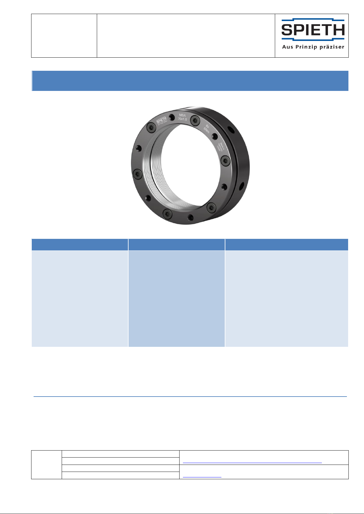
MSA
The Operating Instructions are also available for download at www.spieth-me.de. In case of any questions, please
contact Spieth-Maschinenelemente GmbH & Co. KG directly.
Legal:
Spieth-Maschinenelemente GmbH & Co. KG, Alleenstraße 41, D - 73730 Esslingen
Phone +49 711 930730 0 - Fax +49 711 930730 7
E-Mail: info@Spieth me.de - Web: www.spieth-me.de
KG: Esslingen HQ, Stuttgart county court, company register sect. A 210689
PhG: Spieth-Beteiligungs-GmbH, Esslingen HQ, Stuttgart county court, company register sect. A 210636
Managing director: Dipl.-Ing. Alexander Hund
©Spieth
Proprietary
notice
ISO 16016
Previous document: ba-msa-en1815
See
www.spieth-me.de/english/service-download/catalogue-instructions/
Successive document: N/A
Created: 15 Sep 2023/Fd
For any questions, requests or suggestions, please contact
Checked: 15 Sep 2023/Ax
Original version of the operating instructions
For
Series
Components
Spieth locknuts
(precision locknuts)
MSA
MSA 20x1 MSA 25x1.5 MSA 30x1.5
MSA 35x1.5 MSA 40x1.5 MSA 45x1.5
MSA 50x1.5 MSA 55x1.5 MSA 60x1.5
MSA 65x1.5 MSA 70x1.5 MSA 75x1.5
MSA 80x2 MSA 85x2 MSA 90x2
MSA 95x2 MSA 100x2 MSA 105x2
MSA 110x2 MSA 120x2 MSA 130x3
MSA 140x3 MSA 150x3 MSA 160x3
MSA 170x3 MSA 180x3 MSA 190x3
MSA 200x3

Document
ba-msa-en2336
Page 2 of 10
Operating Instructions
MSA
©Spieth
Proprietary
notice
ISO 16016
Previous document: ba-msa-en1815
See
www.spieth-me.de/english/service-download/catalogue-instructions/
Successive document: N/A
Created: 15 Sep 2023/Fd
For any questions, requests or suggestions, please contact
Checked: 15 Sep 2023/Ax
About the operating instructions for Spieth Locknuts
These operating instructions enable safe and efficient handling of Spieth locknuts. Prior to performing any tasks,
ensure that your staff have carefully read and fully understood these operating instructions.
Notices
The basic requirement for working safely is compliance with all specified safety notices. They can be identified by
the following symbols:
Caution!
In addition to the notices in these instructions, local accident prevention guidelines and national health and safety
regulations also apply.
Table of Contents
1 Information about Spieth Locknuts ....................................................................................................................3
1.1 General information ...................................................................................................................................3
1.2 Safety notices .............................................................................................................................................3
2 Description of Spieth Locknuts...........................................................................................................................4
2.1 Structure.....................................................................................................................................................4
2.2 Mode of action ...........................................................................................................................................4
2.3 Intended use...............................................................................................................................................5
3 Delivery Contents and Storage of Spieth Locknuts.............................................................................................5
3.1 Delivery contents of the Spieth Locknuts ...................................................................................................5
3.2 Storage and shelf life of the Spieth Locknuts..............................................................................................6
4 Assembling Spieth Locknuts ...............................................................................................................................6
4.1 Preparing for assembly...............................................................................................................................6
4.2 Ambience/Environment .............................................................................................................................7
4.3 Assembly process .......................................................................................................................................7
5 Using Spieth Locknuts.........................................................................................................................................9
6 Disassembling Spieth Locknuts...........................................................................................................................9
7 Disposing of Spieth Locknuts............................................................................................................................10

Document
ba-msa-en2336
Page 3 of 10
Operating Instructions
MSA
©Spieth
Proprietary
notice
ISO 16016
Previous document: ba-msa-en1815
See
www.spieth-me.de/english/service-download/catalogue-instructions/
Successive document: N/A
Created: 15 Sep 2023/Fd
For any questions, requests or suggestions, please contact
Checked: 15 Sep 2023/Ax
1Information about Spieth Locknuts
1.1 General information
Please read these operating instructions carefully, paying special attention to our safety notices. These operating
instructions are part of your product and must be kept accessible to the staff in the immediate vicinity of the
product at all times. The operating instructions are also available for download at www.spieth-me.de.
In case of any questions, please contact Spieth-Maschinenelemente GmbH & Co. KG directly.
Caution!
It is mandatory to comply with the recommendations and notices in these operating instructions.
Inform the end user about the contents of these operating instructions.
Spieth-Maschinenelemente GmbH & Co. KG assumes no liability for damage caused by (i)
misinterpreting or nonobserving the operating instructions; (ii) improper use; (iii) incorrect
installation or unauthorised structural changes; or (iv) incorrectly circulating or failure to circulate
the contents of these operating instructions to third parties.
These operating instructions apply on the assumption that the chosen product is valid for the use case. Please see
the related design guide (available at www.spieth-me.de) for specifications, characteristics, and information on
choosing the right Spieth locknuts.
1.2 Safety notices
Spieth locknuts are intended for use on threaded spindles. Please follow all relevant safety notices.
Caution!
Any work carried out with or on the locknut needs to follow the "safety first" guideline!
During operation, keep your hands away from the working area of the locknut!
Prior to any assembly work, switch off all machine drives!
Secure the machine against accidental power-up!
Prior to commissioning the machine, install all safety devices!
Only expert personnel are allowed to perform assembly work on Spieth locknuts. Using Spieth locknuts is only
admissible according to specifications. Spieth-Maschinenelemente GmbH & Co. KG assumes no liability for
violations of the operating instructions or safety notices. This also applies to incorrectly interpreting or circulating
these notices and to incorrect assembly or maintenance.
The locknuts described here are state of the art at the time these assembly instructions are printed. Subject to
changes based on evolved technologies. For international deliveries, follow the safety regulations applicable in
the target country.

Document
ba-msa-en2336
Page 4 of 10
Operating Instructions
MSA
©Spieth
Proprietary
notice
ISO 16016
Previous document: ba-msa-en1815
See
www.spieth-me.de/english/service-download/catalogue-instructions/
Successive document: N/A
Created: 15 Sep 2023/Fd
For any questions, requests or suggestions, please contact
Checked: 15 Sep 2023/Ax
2Description of Spieth Locknuts
2.1 Structure
Spieth locknut bodies
Fig. 1: Schematic representation similar to
Spieth MSA series locknuts
Spieth clamping screws
Radial boreholes for pin spanner DIN 1810 - B
Axial boreholes for face spanner
Identifying features (for original Spieth locknuts)
Spieth logo
Name
Batch number
Locking torque MSfor clamping screws
Spieth MSA series locknuts are assemblies consisting of locknut bodies and clamping screws. The thread inside
the locknut body is interrupted by a groove, separating the locknut body into a load and a locking part. A
diaphragm connects load and locking part.
2.2 Mode of action
Spieth locknuts are precision locknuts. Due to their design they
provide a maximum of precision, combined with utmost locking
properties.
Spieth MSA series locknuts have been designed as all-purpose
precision locknuts (e.g., for locking high-quality fastenings, shaft
bearings, or spindle bearings).
Despite their compact design and the high axial loads occurring
here, Spieth-locknuts guarantee permanent pretension and a
rigid and precisely aligned contact with the bearing for an
immaculately supported spindle.
Fig. 2: Illustration similar to Spieth MSA locknuts
Spieth MSA series locknuts are frictionally engaged one-piece locknuts. Load part and locking part of the locknut
body approach each other purely along an axis via the elastic diaphragm. Actuating the tensioning / clamping
screws arranged in axial direction causes load part and locking part to approach each other purely along an axis.
Since the locking part has been designed as a stable ring, a 360° tessellation using several thread turns is used to
achieve a frictionally engaged clamping on the shaft thread. Tessellation converts the bolt force directly into a
contact force evenly distributed across the entire circumference. Owing to system characteristics, this
automatically aligns the end face at a right angle.

Document
ba-msa-en2336
Page 5 of 10
Operating Instructions
MSA
©Spieth
Proprietary
notice
ISO 16016
Previous document: ba-msa-en1815
See
www.spieth-me.de/english/service-download/catalogue-instructions/
Successive document: N/A
Created: 15 Sep 2023/Fd
For any questions, requests or suggestions, please contact
Checked: 15 Sep 2023/Ax
2.3 Intended use
Spieth locknuts are recognised state of the art. They have been designed to permanently retain pretension and/or
a position on a threaded spindle using frictional locking in the thread. Any other usage is regarded as improper
use.
Spieth-Maschinenelemente GmbH & Co. KG reserves the right to technical changes. In case of any questions or
technical issues, please contact Spieth-Maschinenelemente GmbH & Co. KG.
Caution!
Only expert personnel are allowed to choose, assemble, operate, and service Spieth locknuts.
Use Spieth locknuts only according to product-specific specifications. To ensure proper functioning of the Spieth
locknuts, it is mandatory to comply with the specifications of the connecting components. Detailed information
on the above items can be found in the Design Guide. Operating conditions, e.g. speeds and temperatures at
which the Spieth locknuts are used must not exceed common standards.
Caution!
The user assumes responsibility for proper spindle thread design, for ascertaining the pretension
required for the bearings to be locked, for determining the operating loads and meeting permissible
operating conditions. In case of any questions or technical issues, please contact Spieth-
Maschinenelemente GmbH & Co. KG.
In case operating conditions change, it is mandatory to check if the locknut is still suitable for further use.
Spieth locknuts need to be handled with care, assembled correctly, and used as intended to achieve their full
functional potential. Prior to working with our locknuts, please read these operating instructions carefully. In
particular, please follow all relevant safety notices.
Caution!
It is mandatory to comply with the instructions for use and the general safety notices!
Handle locknuts with care before and during assembly and assemble them according to these
operating instructions. Use only stipulated tools for assembling locknuts.
Incorrect handling or the use of inadequate aids can severely limit, damage, or destroy the machine
element and/or the machine in its functionality.
Spieth locknuts are not meant to be repaired; if repairs are necessary in exceptional cases, only the manufacturer
is allowed to perform them.
3Delivery Contents and Storage of Spieth Locknuts
3.1 Delivery contents of the Spieth Locknuts
Spieth MSA series locknuts have been treated with a preservative. Within the component's packaging bag, a VCI
atmosphere is created providing additional corrosion protection for a certain length of time. Opening the cover or
This manual suits for next models
28
Table of contents
Other SPIETH Industrial Equipment manuals


