spikenzielabs The Rainbow Light Show Manual

For the best outcome, follow each step in order.
We recommend reading this guide entirely before you get started.
The Rainbow Light Show
Hobby Electronics Soldering Kit
Instruction Guide
TM
v1.2
Tools required:
Soldering iron, solder, flush cutters, Phillips head and small flat blade screwdriver, safety glasses, masking tape.

Laser cut acrylic parts and hardware
Electronic components
Button
IC
Resistors
TCRT IR sensors (3)
DC barrel jack
3pin screw terminal Socket
220uf capacitor
0.1 capacitor Transistor
5v 2A Ac Adapter
16 LED Strip
PCB
Nuts
Screws
Stand
Under bezel washers
Bezel
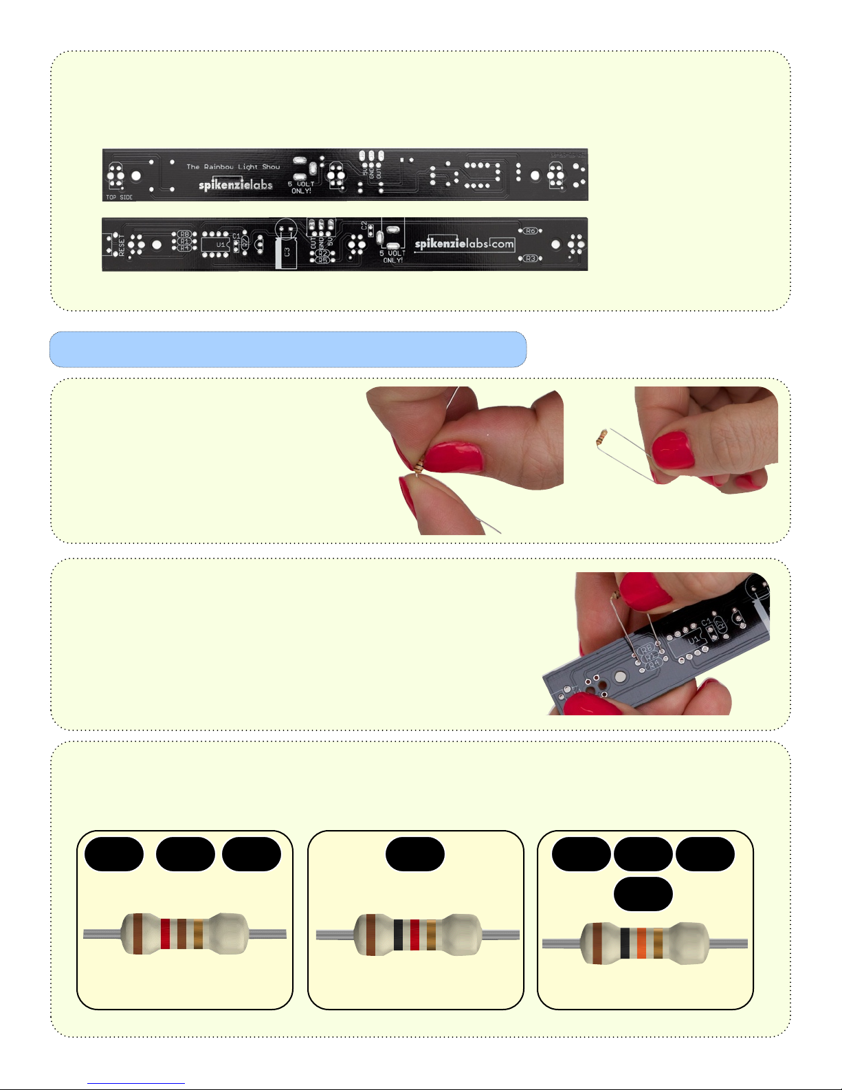
The Rainbow Light Show PCB will have most components soldered to the bottom of the board, as well some
on the top. In all cases, the component is soldered onto the side with a white printed outline.
Top Side of PCB
Bottom Side of PCB
Resistor bending:
Bend each of the resistors like in these photos:
You want to have the bend of the leg
as close as possible to the body of the resistor.
Resistor preparation and soldering
It is important to place each resistor in the appropriate area on the PCB.
Prepare one resistor at a time, and insert it into the proper location on
the PCB.
Be sure to install the resistors on the bottom side of the PCB.
Use this chart to place the proper resistor in the right location on the PCB.
Note the R numbers printed on the PCB.
1k ohm [brown/black/red] 10k ohm [brown/black/orange]
Resistor graphics by samstechlib.com
120 ohm [brown/red/brown]
R1 R2 R3
R8
R7R4 R5 R6
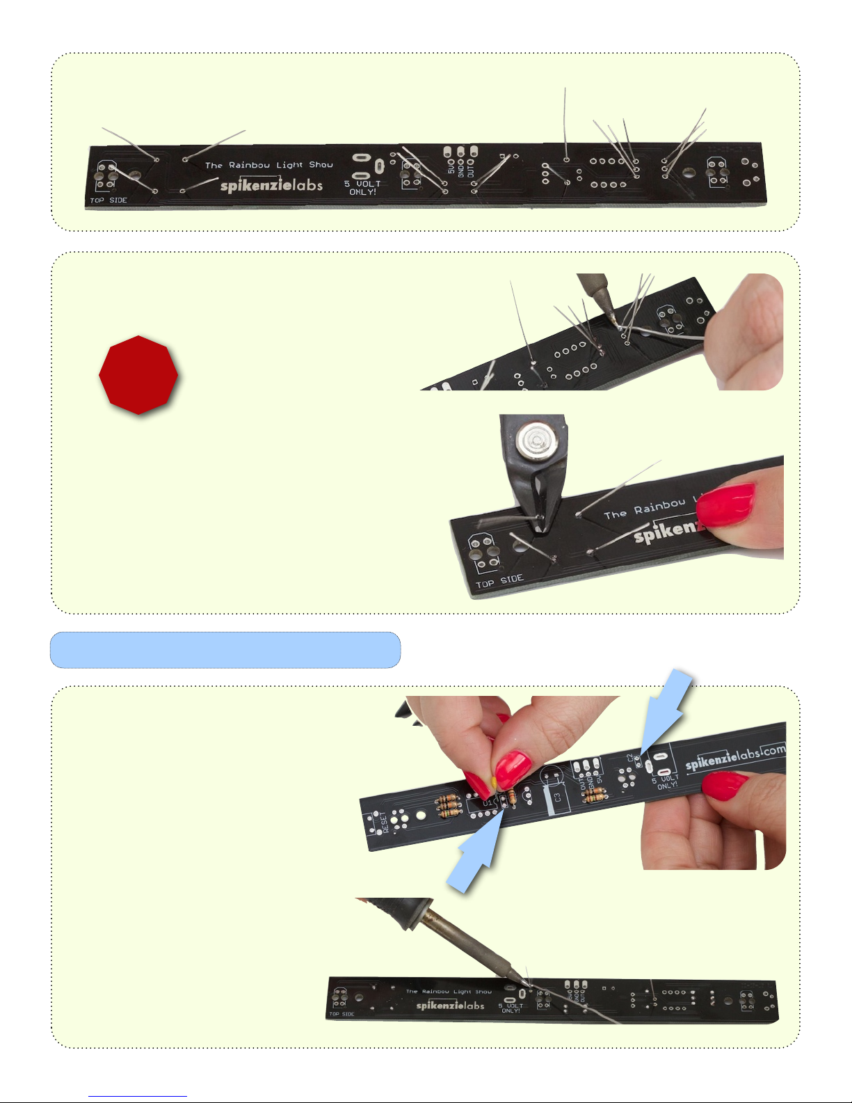
Flare out the legs to keep them in place. Be sure that the body of the resistor is flush against the PCB.
Solder the resistors in place. Make sure you don’t
forget to solder any of the legs.
Snip off the ends of the legs. Be sure not
to scratch the surface of the PCB. Keep
your safety glasses on!
Do this for each resistor leg.
!
Safety Glasses On!
Capacitor preparation and soldering
Place the capacitors in the two locations
as seen in these photos. Marked as 0.1uf
on the PCB.
Orientation does not matter for these.
Flare the legs out as your did for
the resistors, and then solder both
capacitors in place.
Snip the ends of the legs.

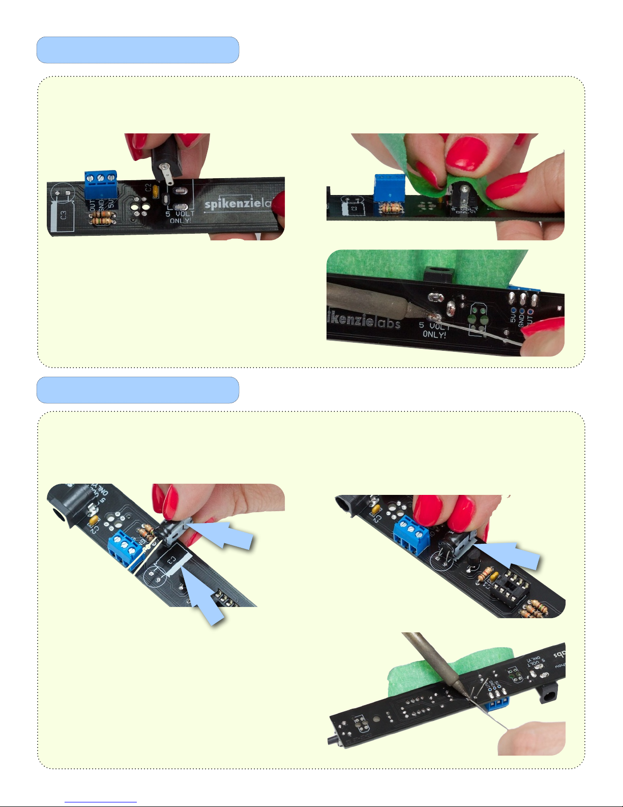
The IC socket
Transistor preparation
The IC socket has a notch on one side.
The PCB has a printed notch. When
you are mounting the socket to the
PCB, make sure the notch on the
socket is lined up with the notch printed in
white on the PCB.
!
Mind the notch!
Solder the socket in place. You can use a
piece of masking tape to hold the socket in
place while soldering.
Cut the 3 leg transistor from the tape. Look at it, and note that there is a rounded
side as well as a flat side to the body. This is important for the next step.
Line up the transistor so that the flat side matches the
white printed outline on the PCB.
Solder the transistor in place.

The calibrate / wake button
Line up the button over the PCB. Mount the right angle button to the PCB.
Note: The button has 4 legs.
The button will hold itself in place. Make
sure the button to flush to the surface of
the PCB.
Solder the 4 legs, and trim the excess.
Screw terminal block
Place the 3 pin screw terminal block over the PCB.
Note the orientation of the wire connect holes.
Slide the 3 pins through the holes. Hold in place
with a piece of masking tape.
Solder the 3 pin screw terminal block in place.
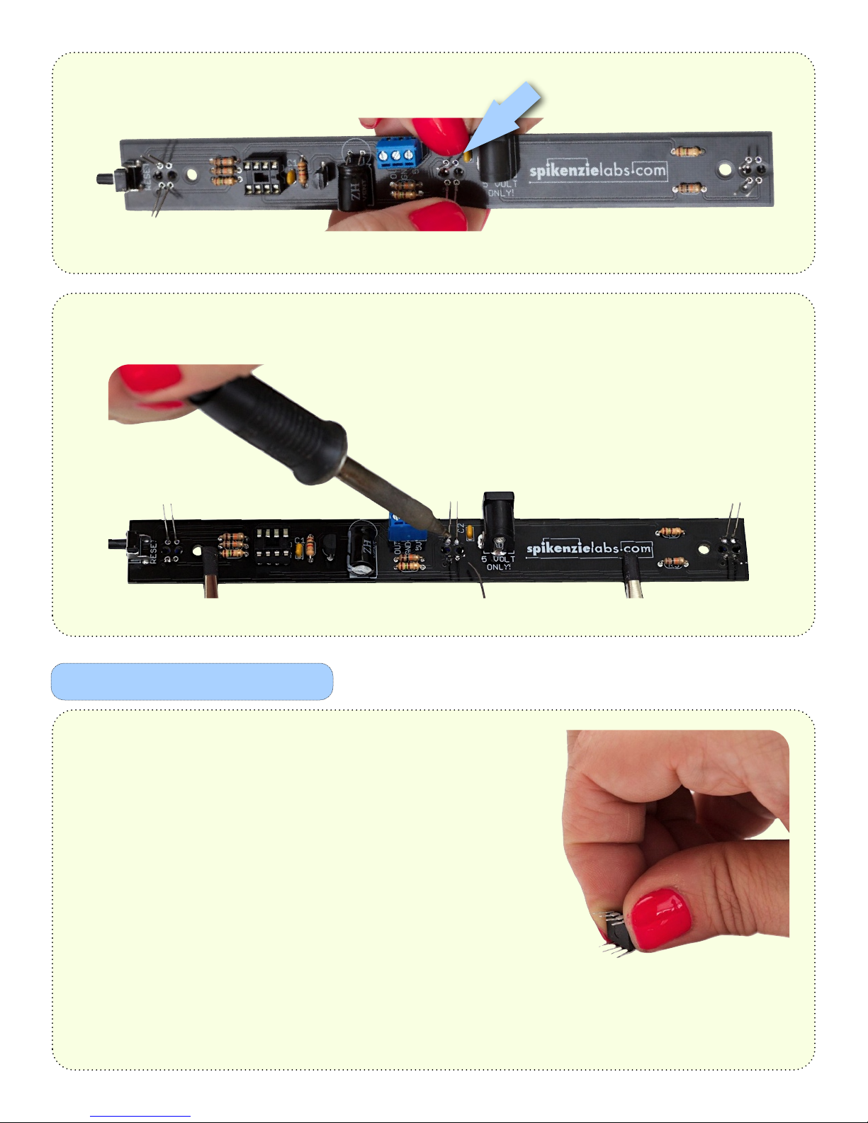
DC barrel jack installation
220uf capacitor
Place the DC barrel jack over the PCB.
This can only be installed in one direction.
Slide the 3 tabs through the slots in the PCB, and
hold in place with a piece of tape.
Solder the DC barrel jack in place.
Line up the white indicator stripe on the body of
the 220uf capacitor. Proper polarity is important
for this component.
Insert the 2 legs, and lay the capacitor down like in
this photo. Note the white stripe on the capacitor
and the indicator on the PCB.
Hold the capacitor in place with a piece of tape,
and solder both legs. Trim the excess.
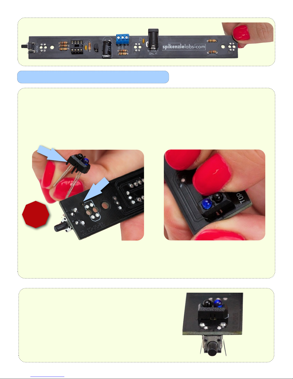
IR Sensors
The bottom of your PCB should now look like this:
Next you will be installing the 3 IR sensors on the top side of the board, and soldering on the bottom side.
Note the corner insertion pin on the sensor. It fits
inside the mount hole on the PCB. The body shape is
also printed in white on the PCB for proper installation.
Slide the 4 legs through the PCB, and push the IR
sensor all the way down. The insertion pin will
mate with the hole in the PCB.
!
Mind the notch!
Don’t press on the 2 LEDs. Hold the sensor
from the sides. If you press too hard on the
leds they may break.
A properly mounted sensor should look like this before soldering.
If the bottom of the IR sensor plastic housing
has a deformity that stops it from laying flat
on the PCB, trim the plastic with your snips,
or a hobby knife.
Flare out the legs of the IR sensor as you have in previous steps.
Solder and trim the 4 legs for each of the sensors.
IC preparation
When manufactured, the legs are flared out slightly.
To be mounted to the socket, the legs need to be
closer to the body of the IC.
Remove the IC from the antistatic foam. Hold it firmly
on either end, and press the legs down on a flat hard
surface.
You can test fit it on the socket if you think you have
them straight enough.
Be Careful when soldering the sensors on the
already populated bottom side of the PCB.
You don’t want to accidentally burn any of the
components. You may need to rotate the PCB
to get a good angle for each of the 4 pins for
each sensor.

The IC, socket and PCB all have a notch indicating
the correct orientation for the IC. Make sure they
are all lined up. If you insert the chip in the wrong
orientation, it will not work.
!
Mind the notch!
Place the IC over the socket. When you see that all of the legs are lined up, gently press down until it is
seated flat against the socket..
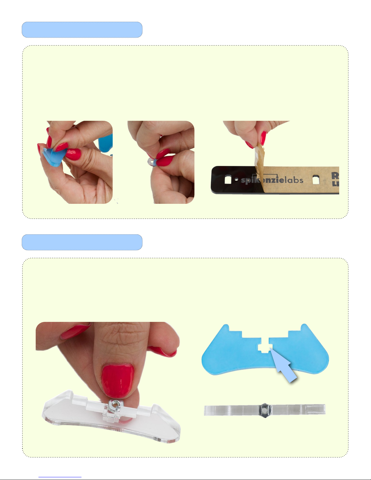
Preparing the acrylic parts
The stands
Peel the protective plastic and paper from the 2 stands, washers and top bezel. For the pieces of paper
that remain on the black acrylic, scratch at a corner with your fingernail, and then lift it away. Be careful
not to scratch, bend or flex the acrylic. If the surface picks up fingerprints, we recommend cleaning
acrylic surfaces with Windex, and a lint free cloth. Never use alcohol based cleaners on acrylic.
Slide a nut into each stand. If the nut keeps sliding out the other side, you can put a small piece of
masking tape on either side to hold it centered in place, until the screws are tight.

Place the fully populated PCB over the stands. Top side up. Center the screw holes directly over the center
of each nut.
Place a washer over both of the screw holes on the PCB.
Make sure that the nut has not slipped out. You will be
able to see it if you look directly through the hole, from
the top down.
Place the bezel over the PCB and washers.
The ‘reset’ side of the bezel, goes over
the button end of the PCB.
Slide a screw into each screw hole in the bezel.
Slowly tighten each.
Do not over tighten. You may crack the acrylic.

Loosen the 3 flat blade screws of the screw terminal,
about 4 turns each.
Line up the Red wire, with 5V.
Black wire with GND.
Yellow wire with OUT.
Double check to be sure this pattern is correct before
connecting the AC adapter.
Insert and screw down the Red wire.
Insert and screw down the Black wire.
Insert and screw down the Yellow wire.
Plug in the AC adapter in to the wall, and then
plug it in to the DC barrel jack.
ONLY EVER USE THE SUPPLIED AC ADAPTER
THIS DEVICE RUNS ON 5V DC ONLY
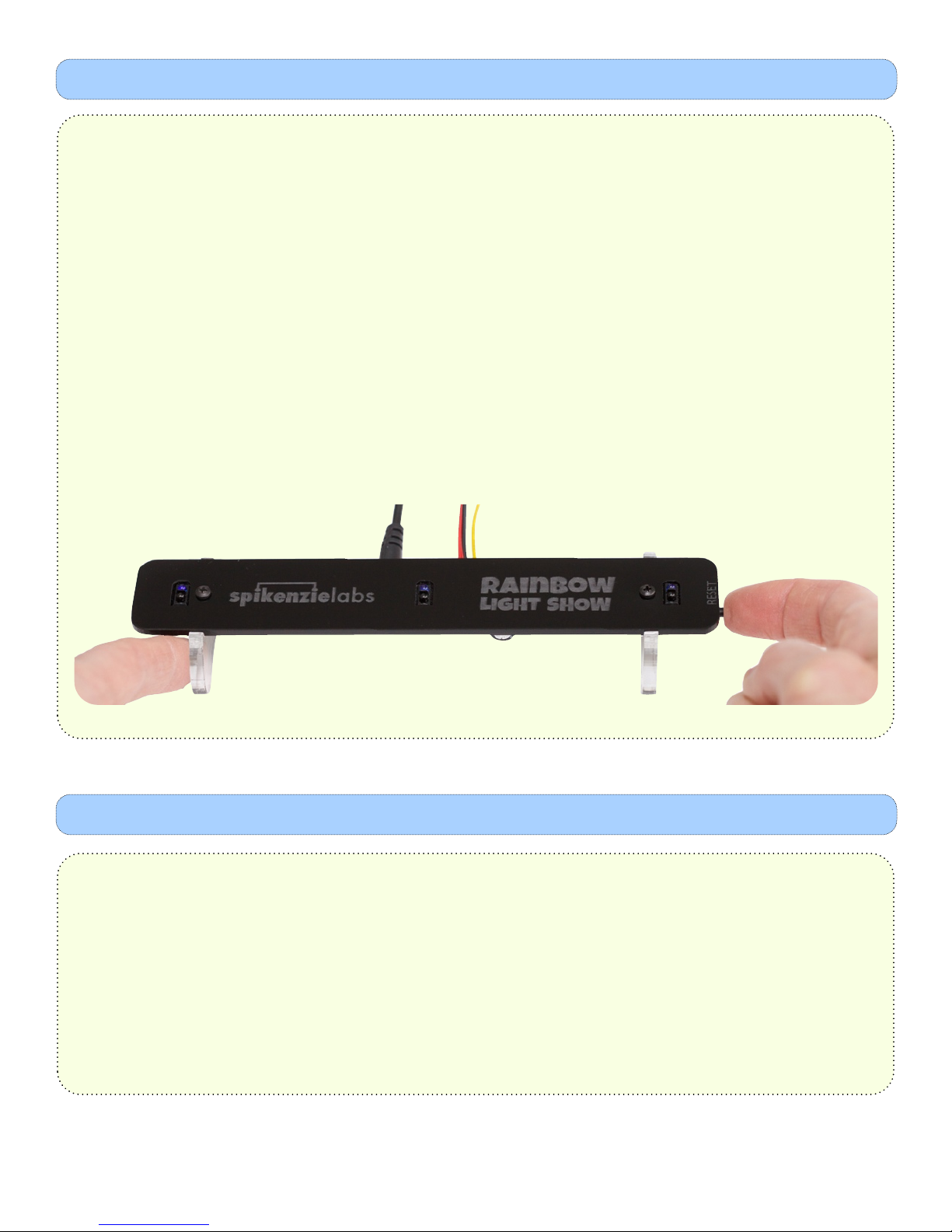
In order to allow the RLS to produce nice smooth color transition and avoid false triggers we added a calibration
function. When the RLS is first powered on (or awoken from sleep mode) the calibration function is run. At any
time if you see random LEDs lighting up, (even when your hands are not near the RLS) simply press the "reset"
button and the RLS will re-calibrate.
When recalibrating, do not stand too close to The Rainbow Light Show or put a hand over any of the sensors.
The best way is to place you left index finger to the left of the left stand and use your right index finger to press
the reset button on the lower right hand side of the RLS.
After 30 seconds of inactivity, The Rainbow Light Show will go to sleep. To wake it up, simply press the reset
button in the same way you would to recalibrate it.
Quick Start:
The Rainbow Light Show • How it works
What is the RLS?
The RLS is based on our SPLixel LED driver, that is, a microprocessor that is specially programmed to light up addressable RGB
(Red, Blue and Green) LEDs.
We modified the SPLixel programming for the RLS to read three sensors and use those readings to produce an intensity of red,
green and blue light on a LED. Using a shifting algorithm, the colors displayed from the first LED are shifted to the second and then
to the third and so on, all the way up to 64 LEDs.
How it works:
The RLS has three sensors. These sensors are IR (infrared) light proximity sensors. On each sensor there are two parts. The first part
is an IR LED, that is shining a beam of IR light upward. The IR beam is invisible to the naked eye. If you look though your phone's
camera you may be able to see it. The second part is a phototransistor. When the phototransistor is exposed to IR light it allows a
current to pass through..
Since both the IR LED and IR phototransistor are pointed upwards on the RLS, we need something to reflect the IR light back into the
phototransistor. This is where your hand comes in! When you bring a hand closer to the RLS's sensors more IR light is reflected back
into the phototransistor and more current passes through. The microprocessor then reads an analog (read a variable) voltage
produced due to the changing current flowing though the phototransistor. It does this for all three sensors and It uses these varying
voltages to decide how bright to light up the red, green and blue channels of each LED.
Calibration:
Did you know that your TV remote also uses IR light? So that your TV does not change channels by itself, TV manufactures use a
special type of phototransistor that only works when a specific frequency of IR light is received (typically 38 - 40 khz). The TV
remote is actually flashing an IR signal to the TV!
The type of IR proximity sensors used in the RLS do not have any special filtering. They can pick up stray IR light from other sources.
This will make a series of random colors flow along on your RLS LEDs. We chose not use IR phototransistors with filtering, since all
the models that we tested were either excessively expensive or did not work well to produce a nice smooth analog voltage.
In order to allow the RLS to produce nice smooth color transition and avoid false triggers we added a calibration function. When the
RLS is first powered on (or awoken from sleep mode) the calibration function is run and at any time if you see random LEDs lighting
up, (even when your hands are not near the RLS) simply press the "reset" button and the RLS will re-calibrate.
How to Calibrate your RLS:
As lighting changes or people move around causing both reflections or shadows you may have to recalibrate your RLS.
Remember, IR light is invisible to your eyes so even if you don't see the "light" changing, light on the IR spectrum may have
changed.
When the RLS does a recalibration, it turns off the three IR LEDs on the sensors and then reads the value of IR light coming in. It is
important the RLS be able to see all of the ambient IR light while it is recalibrating. So, it is important that you do not stand too
close to it or put a hand over any sensor while recalibrating. The best way is to place you left index finger to the left of the left
stand and use your right index finger to press the reset button on the lower right hand side of the RLS.
When the RLS does a recalibration it reads the intensity of IR light coming in. It then adds a safety cut-off value to this reading and
will then ignore any IR reading that is below this threshold. What these means for you, is that your RLS will work in many different
lighting conditions. It prefers to be used in areas that are not too bright. Also, when the RLS is calibrated in a bright area, the
threshold is set much higher, so in fact the RLS will be less sensitive to your hand. This means that your hand will have to be closer
to the top of the RLS before it starts to produce colors.
Table of contents


