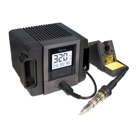
Quick 3202 User manual

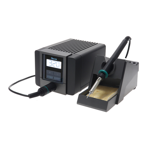
QUICK 3202
Lead Free Soldering Station
OPERATION MANUAL
Thank you for purchasing the unit. It is designed for lead free soldering.
Please read this manual carefully before use and keep it for future
reference.

Ⅺ. TIPS
200-2.4D
200-1.6D
200-1.2D
200-3.2D
200-4.2D
200-SB
200-B
0.5
0.5
3.5
45°
15
25°
45°
2
10
1.5
10
4
R0.5
9
2
R0.5
200-2C
7.5
2
12
3
45°
1.2
3.5
200-H
10
3.7
200-1C
12
3.5 2
200-0.8C
45°
12
200-K
1.5
200-SK
R0.2
12
45°
12
45°
1.5
12
45°
200-2B
200-3C
R1
R0.2
200-I
2
12
3
2.5
12 2
200-4C
2
12
200-J
12
3
2
45°
12
12
2
3
12
1
0.8
0.8
Table of Contents
Ⅰ. Safety Instruction……………………………………………………………1
Ⅱ. Specification…………………………………………………………………3
Ⅲ. Characteristic…………………………………………………………………4
Ⅳ. Connection & Operation the Soldering Iron………………………………4
4.1 Iron Holder………………………………………………………………4
4.2 Connection……………………………………………………………5
4.3 Operation of the Soldering Station…………………………………6
4.3.1 Favorite Temperature Setting…………………………………6
4.3.2 Temperature Setting……………………………………………7
4.3.3 Turn On / Turn Off the Sound…………………………………7
4.3.4 Sleeping and Resume…………………………………………8
Ⅴ. Parameter Setting……………………………………………………………8
5.1 Input Right Password…………………………………………………9
5.1.1 Into the Parameter Setting……………………………………9
5.1.2 Input the Password……………………………………………9
5.2 Parameter Menu………………………………………………………10
5.3 Sleeping Time Set……………………………………………………10
5.4 Work Mode Set………………………………………………………11
5.5 Password Set…………………………………………………………12
Ⅵ. Temperature Calibration…………………………………………………12
Ⅶ. Select a Correct Tip………………………………………………………13
Ⅷ. Use and Maintenance of the Tip…………………………………………14
8.1 Use of the Tip…………………………………………………………14
8.2 Maintenance of the Tip………………………………………………14
Ⅸ. Error messages……………………………………………………………16
Ⅹ. Check and Replace the Soldering Iron…………………………………16
10.1 Check the Soldering Iron……………………………………………17
10.2 Disassembling the Iron Handle……………………………………17
10.3 Measure the Resistance before Replacing…………………………18
10.4 Measure the Resistance after Replacing…………………………18
Ⅺ. TIPS…………………………………………………………………………19
Page 19

Ⅰ. Safety Instruction
WARNING
In this instruction manual,“Warning ”“ Caution”and “Note”are defined as
followings:
WARNING: Misuse may potentially cause death or serious injury to the
user.
CAUTION: Misuse may potentially cause injury to the user or physical
damage to the objects involved. For your own safety, be sure
to comply with these precautions.
CAUTION
When the power is on, the tip temperature is very high. Follow the
precautions strictly as mishandling may cause burn or fire:
Do not use the unit for other applications.
Do not touch the metallic parts near the tip.
Do not use the product near flammable items.
Inform other people in working area that the temperature of this unit
could be very high during the work. Power the unit off when the work is
finished to avoid danger.
Power off the unit and wait till the temperature cools down to room
temperature when replace or install the parts.
To prevent damage to the unit and ensure a safe working environment,
be sure to comply with the following precautions:
Only use this unit with rated voltage and frequency (refer to the
trademark back of equipment).
If there’s any damage to the unit, stop using it.
1. Pull out the iron tip by the needle at the soldering handle holder. the iron tip
and the iron tip encloser ①are in together.
2. Pull out the heating element③ towards the iron tip of the iron handle⑧.
3. Push the handle cord(12)lightly forwards and pull the PCB for line
connection⑥and handle cord out of the iron handle⑧ (towards the tip of the
handle).
NOTE: Do not use metal tools such as pliers to remove tip or Tip encloser from
the iron handle.
10.3 Measure the Resistance before Replacing
NOTE: Measure the resistance when the heating element is at room temperature.
1. Resistance value of heating element is <4Ω.
2. If the resistance value is not normal, replace the heating element. Refer to the
instructions included with the replacement part.
10.4 Measure the Resistance after Replacing
After replacing the heating element:
1. Measure the resistance values “a” and “b” to confirm that the leads are not
twisted and that the grounding wire is properly connected.
2. The pins of the handle plug are as followings:
Pin1: Blue Pin2: Red
Pin3: Green Pin4: Metal layer of shielding cord
Pin5: White of shielding cord Pin6: White
Page 18 Page 1

10.1 Check the Soldering Iron
1. Pull out the plug and measure the resistance value between the pins of the
connecting plug when the heating element cooling down to the room
temperature.
2. If the value of ‘a’ is different from the values in the following table, replace
the heating element or cord assembly. Refer to the following steps.
3. If the value of ‘b’ is over the below value, remove lightly the oxidation in the
joint part of the tip and the heat element with sandpaper or steel wool.
a. Between pins 4&5 (Heating
Element) <4Ω(Normal)
b. Between pins 3& Tip <2Ω
10.2 Disassembling the Iron Handle(for example
901A Iron hand)
This machine is equipped with a 3-wires grounding plug and must be
plugged into a 3-terminal grounded socket. Do not modify plug or use
an ungrounded power socket. If an extension cord is necessary, use
only a 3-wire extension cord that provides grounding.
Do not use the unit for other applications except soldering.
Do not rap soldering iron against the workbench to shake off residual
solder, otherwise the iron will be damaged by shocks.
Do not modify the unit.
Only use the original replacement parts.
Keep the unit dry. Don’t use or disconnect the unit with wet hands.
The soldering process will produce smoke, so make sure the area is
well ventilated.
While using the unit, don’t do anything which may cause bodily harm or
physical damage.
Children don’t know the danger of electrical appliances. Keep it away
from children.
Page 2 Page 17

Ⅱ. Specification
Power 220V
Power consumption 90W
Temperature Range 100℃~500℃ (Decide by working mode)
Highest Ambient Temperature 40℃
Temperature Stability ±2℃/Without air flow and no load
Tip to Ground Resistance <2Ω
Tip to Ground Potential <2mV
Heating Element Electromagnetic heater
Dimension 96(W)×160(L)×135(H) mm
Weight (not including handle length) 1.38Kg
Iron hand Can select 901A or 901C iron hand; 901A
match 200 tips,901C match 200G tips
* The tip’s temperature is measured by 191/192 thermometer.
* Specifications and design subject above may be changed without notice.
(2) Choose a low and suitable temperature, this will protect the tip from
being oxidized.
(3) Use fine point tips only when necessary. The plating on fine precision
tips is less durable than the plating on blunter tips.
(4) Do not use the tip as a prying tool. Bending the tip will cause the plating
to crack, shortening tip life.
(5) Use the minimum activation flux necessary to do the job. Higher
activation flux is more corrosive to the tip plating.
(6) Extend tip life by switch the system off when not in use.
(7) Don’t apply pressure to the tip. More pressure does not equal more heat.
To improve heat transfer, use solder to form a thermal bridge between
the tip and the solder joint.
Ⅸ. Error messages
Various error messages will be displayed when there is something wrong with the
unit.
Sensor error: If there is a failure in the sensor or anywhere in
the sensor circuit, “S-E” will be displayed and power to the
soldering iron handle will be cut off.
Heater error: If power cannot be sent to the soldering iron, the
display window will show “H-E”. This indicates the possibility of a
heater malfunction.
Ⅹ. Check and Replace the Soldering Iron
When there is something wrong with the soldering iron, you can check and test it.
If it is broken, replace the broken element.
S
-
E
H - E
Page 3 Page 16
Table of contents
Other Quick Soldering Gun manuals