4
ENGLISH
OPERATION
LED lights
Red LED -ON- when lit, it indicates that the station is
plugged in the mains.
Green LED -READY- when lit, it indicates that the
system is ready and correctly set for working.
The green led light is on after a few seconds, is the
time needed to carry on the self-checking system.
The green light is pulsing when the desoldering iron
is in sleep mode.
If the green led is not lit, the reason why, will be one
of the following:
1. The desoldering iron is not plugged in.
2. The maximum available power has been
exceeded for too long - e.g. in a very thick
desoldering at the high repetition rates.
3. The desoldering heating element has a short
circuit or an open circuit.
4. Any other trouble preventing the system from
working properly.
The handpiece will reset itself automatically should
the cartridge short circuit or go open circuit.
Should the handpiece be subject to:
-An electrical surge or the cartridge has not been
fitted correctly.
Please turn the unit off and switch on again to reset.
When pressing the button of the desoldering iron
handle, one of the two leds in the area marked
SUCTION will light up:
Green light -SUCTION- indicates the correct
functioning of the desoldering iron.
Red light -SUCTION- indicates a blockade within
the vacuum circuit.
This can be caused by the following:
-The tip of the desoldering iron is blocked.
Sleep function
One of the Series Advanced features is that when
the desoldering iron is placed in the holder, the
temperature at the tip drops automatically to the
sleep temperature. This function is only
possible because of the quick response time
which does not make the user realise the
temperature rise to reach the selected
temperature. Also by this, the oxidation of the
tinning of the tip is considerably reduced and
tip life is extended.
To indicate that the desoldering iron is in sleep-
mode, the green led starts pulsing. These
parameters can be modified using the Console
AC 2600 Ref. 2600000.
In order to take advantage of the above
mentioned feature and as a security measure,
it is necessary to place the desoldering iron
on stand when the iron is not being used.
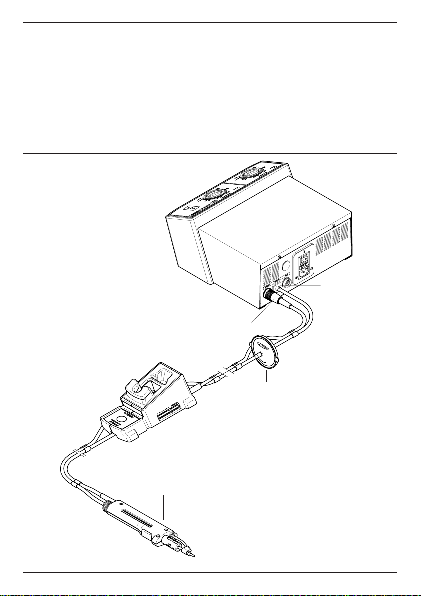
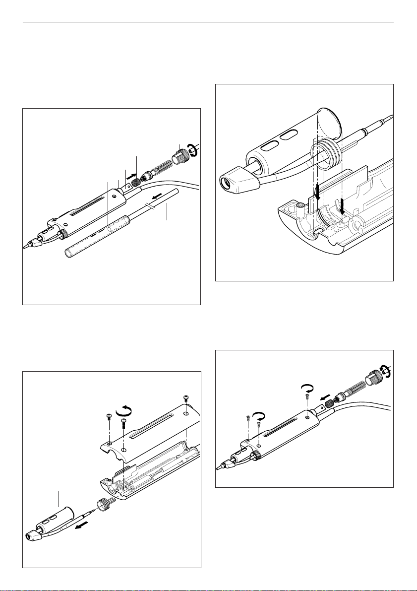
DR 5600 Ref.5600000
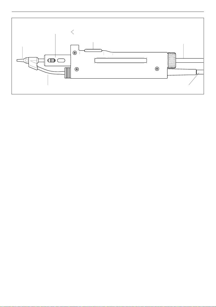
Desoldering tip
Heating element
Pushbutton vacuum pump Vacuum hose
Desoldering iron cable
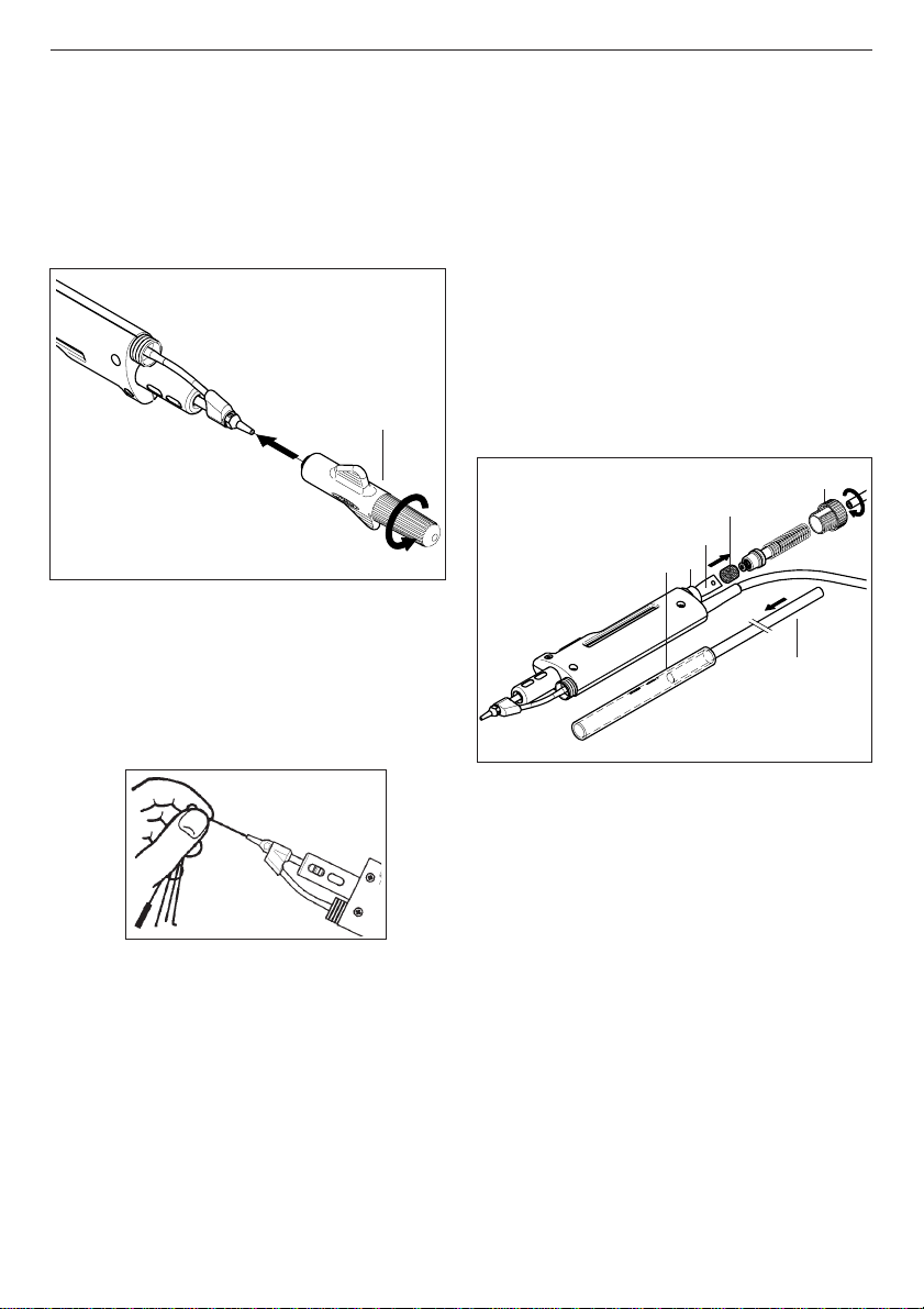
Solder tin deposit Metal
Glass
-The solder tin deposit is full.
-The filter of the desoldering iron is dirty.
-The station’s external desoldering air filter is
dirty.
Only for users of AC 2600 console ref. 2600000.
If you lock the working temperature thanks to the
console, the green LED -READY- will remain on
while the dial is set at the locked temperature.
If the dial is not set at the locked temperature,
the green LED -READY- will be blinking. The
farther the dial will be set from the locked
temperature the slower the blinking pace will be.