Spinner SmartLoad 546435C0300 User manual

SPINNER I Product Manual
Original instructions
SmartLoad 25 kW
with Outdoor Heat Exchanger
BN 546435C0300
BN 546435C0301
products.spinner-group.com

Data subject to change without notice │ 10086219│ Issue B│ 2023-09-28
www.spinner-group.com
2 / 27
Content
1Safety .......................................................................................................................................................3
1.1 About this product documentation............................................................................................................3
1.2 Intended use.............................................................................................................................................3
1.3 Improper use ............................................................................................................................................3
1.4 Qualifications of personnel.......................................................................................................................3
1.5 Safety signs and symbols ........................................................................................................................4
1.6 Signal words for hazard seriousness .......................................................................................................4
1.7 Grouped safety messages for SPINNER broadcast products .................................................................5
2Product identification................................................................................................................................7
3Delivery content........................................................................................................................................7
4Function....................................................................................................................................................8
4.1 General.....................................................................................................................................................8
4.2 Coolant.....................................................................................................................................................8
4.3 External heat exchanger ..........................................................................................................................8
4.4 Coolant circuit of the liquid cooling system..............................................................................................8
4.5 Interlock loop............................................................................................................................................9
4.6 Operating and display elements.............................................................................................................10
4.7 Maintenance cycle..................................................................................................................................10
5Storage...................................................................................................................................................10
6Transportation ........................................................................................................................................11
7Installation ..............................................................................................................................................11
7.1 Mechanical installation...........................................................................................................................12
7.2 Electrical installation...............................................................................................................................15
7.3 Filling of the coolant circuit.....................................................................................................................17
8Commissioning and normal operation....................................................................................................18
9Maintenance...........................................................................................................................................19
9.1 PLC clock time setting............................................................................................................................20
9.2 Deaeration of the cooling circuit.............................................................................................................20
9.3 Checking glycol concentration ...............................................................................................................22
9.4 Coolant exchange ..................................................................................................................................23
10 Warranty.................................................................................................................................................24
11 Repairs...................................................................................................................................................24
12 Demounting............................................................................................................................................25
12.1 Disconnect in the following order: ..........................................................................................................25
12.2 Empty the cooling circuit: .......................................................................................................................26
13 Disposal..................................................................................................................................................26
14 Spare Parts ............................................................................................................................................26
15 Accessories............................................................................................................................................26
16 Contacts .................................................................................................................................................27

Data subject to change without notice │ 10086219│ Issue B│ 2023-09-28
www.spinner-group.com
3 / 27
1 Safety
1.1 About this product documentation
The Spinner group makes every effort to keep the safety standard of our products up to date to be able to
offer our customers the highest possible degree of safety. Our products are designed and tested in
accordance with the relevant safety standards. There is, however, still a danger of personal injury or damage
to equipment if this chapter and the safety instructions in this documentation are not complied with. This
documentation aims at persons commissioned with the transport, installation, commissioning, operation,
cleaning, maintenance, repairs, demounting and disposal of SPINNER SmartLoads. Read this
documentation completely and particularly the chapter "Safety", before working with the product. Keep this
product documentation available at the site and pass it on to the subsequent users. For all questions
regarding the safety you can contact SPINNER at any time.
1.2 Intended use
The intended use of the product is to terminate RF high power coaxial transmission lines. The SmartLoad
BN 546435C0300 or 546435C0301 is designed to absorb RF power of max. 25 kW in broadcast or industrial
applications. The indoor unit of the SmartLoad shall be used only in operating rooms with restricted access.
Access for authorized persons shall be regulated by the operator.
Details and other limits are given in the attached data sheet 10086250.
The intended use of the product is assumed, if it is used in accordance with the requirements of the
applicable product documentation and within its performance limits (see attached data sheet, circuit diagram,
environmental conditions, material data sheet of the SPINNER coolant and the following safety instructions).
Applicable local or national safety regulations and rules for the prevention of accidents must be observed in
all work performed in conjunction with the product.
1.3 Improper use
The improper use of the product includes the use of the SmartLoad:
•indoor unit in operating rooms with unrestricted access
•indoor unit in outdoor applications
•in explosion-prone atmosphere
•without correctly connected interlock system
•with covered inlet or exhaust air openings
•with modifications not authorized by SPINNER
•in damaged condition
•for private purposes
•in conditions and environments beyond the limits given in this product documentation
Any other use than described in the chapter intended use and in this product documentation is improper use
and therefore inadmissible.
1.4 Qualifications of personnel
Installation, commissioning, operation, maintenance, repairs and demounting of the product require electrical
and mechanical specialized knowledge. In order to ensure the safe use, these activities may therefore only
be carried out by qualified technical personnel or an instructed person under the direction and supervision of
qualified personnel. Qualified personnel are those who, due to professional training, knowledge and
experience as well as their understanding of the relevant regulations, are able to assess the work assigned,
to recognize possible hazards and to institute appropriate safety measures.
Qualified personnel must have appropriate safety equipment and must be trained in first aid.
The use of the product requires special training and a high level of concentration. It must be ensured that
persons who use the product are physically, mentally and emotionally able to comply with the requirements,
otherwise injuries or material damage may occur. The employer or operator must choose suitable personnel
for use of the product.
Data subject to change without notice │ 10086219│ Issue B│ 2023-09-28
www.spinner-group.com
4 / 27
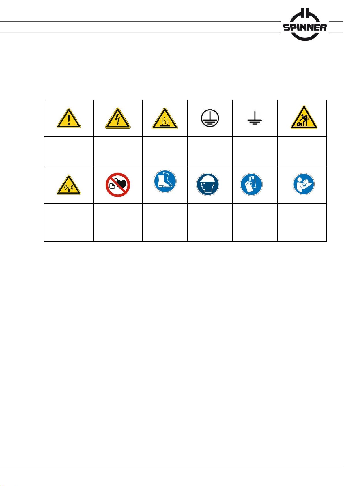
1.5 Safety signs and symbols
Safety signs are used on warning labels, stickers, in the product documentation and on the packaging of the
product.
Warning!
General hazard
Warning!
Danger of
electric shock
Warning!
Hot surface
PE terminal
Earth
Warning!
High weight
Warning!
Non-ionised
electromagnetic
radiation
No access for
persons with
pacemakers
Use safety shoes
Use safety helmet
Use safety gloves
Observe product
documentation
1.6 Signal words for hazard seriousness
Signal words are used on warning labels, stickers, in the product documentation, on specific danger spots
and on the packaging of the product. They indicate the hazard seriousness in safety messages.
DANGER Indicates a hazardous situation conveying great risk which, if not avoided, will result in death
or serious injury.
WARNING Indicates a hazardous situation conveying moderate risk which, if not avoided, could result in
death or serious injury.
CAUTION Indicates a hazardous situation conveying minor risk which, if not avoided, may result in minor
or moderate injury.
NOTICE Indicates the possibility of faulty operation that can damage the product.
It is essential to make sure that the signal words described here are always used only in connection with the
related product documentation and the related product. The use of signal words in connection with unrelated
products or documentation can result in misinterpretation and thus contribute to personal injury or material
damage.

Data subject to change without notice │ 10086219│ Issue B│ 2023-09-28
www.spinner-group.com
5 / 27
1.7 Grouped safety messages for SPINNER broadcast products
Entire or multiple phases of product lifecycle
•Unless otherwise specified, these products are not protected against penetration of liquids, gases, steam,
etc. Failure to comply could result in electric shock or product damage, which could also lead to serious
injury.
•Blocking of constructive openings on the product (ventilation slots, fine leaks etc.) must be prevented,
because these are necessary for product operation. Failure to comply could lead to overheating and
could result in burns, fire and electric shock.
•Any object that is not designed to be placed in the openings of the housing must not be used for this
purpose. Doing so can cause short circuits inside the product and could result in electric shock, fire or
injury.
•Depending on the function, certain products such as RF radio equipment can produce an elevated level
of electromagnetic radiation. Considering that unborn babies require increased protection, pregnant
women must be protected by appropriate measures. Persons with pacemakers may also be exposed to
risks from electromagnetic radiation. The employer/operator must evaluate workplaces where there is a
special risk of exposure to radiation and, if necessary, take measures to avert the potential danger.
•As with all industrially manufactured goods, the use of substances that induce an allergic reaction
(allergens) such as nickel cannot be generally excluded. If you develop an allergic reaction (such as a
skin rash, frequent sneezing, red eyes or respiratory difficulties) when using a SPINNER product, consult
a physician immediately to determine the cause and to prevent health problems or stress.
•Should a fire occur, the product may release hazardous substances (gases, fluids, etc.) that can cause
health problems. Therefore, suitable measures must be taken, e.g. protective masks and protective
clothing must be worn.
Transport
•The product may be very heavy. In some cases, the user may require suitable lifting gear and means of
transportation to avoid back or other physical injuries.
•Transport the product only in the original packaging. Do not unpack until immediately prior to installation.
Failure to comply could result in death or serious injury.
Installation
•Do not place the product on heat-generating devices such as radiators or fan heaters. The ambient
temperature must not exceed the maximum temperature specified in the product documentation or in the
data sheet. Product overheating could result in burns, fire and electric shock.
•Do not place the product on surfaces, vehicles, cabinets or tables that for reasons of weight or stability
are unsuitable for this purpose. Always follow the installation instructions of the manufacturer when
installing the product and fastening it to objects or structures (e.g. walls and shelves). An installation that
is not carried out as described in the product documentation could result in death or serious injury.
•Mains driven products must be operated only from a TN power distribution system. The operator is
responsible for using an appropriate and sufficiently dimensioned AC power line. The AC power line must
be externally fused according to the product documentation. Failure to comply could result in fire or
electric shock.
•Operation of products with protection class I according to EN 61140 is permitted only with a mains cable
with protective earth connection. The protective conductor continuity must be inspected by an electrically
skilled person. Failure to comply could result in electric shock.

Data subject to change without notice │ 10086219│ Issue B│ 2023-09-28
www.spinner-group.com
6 / 27
•All externally connected circuits for controlling, alerting and signalling have to be fed from ES1 type
sources acc. to IEC 62368-1 only. The current in these circuits has to be externally limited by means of
fuses to values indicated in the product documentation. Failure to comply could result in fire and electric
shock.
•Dangerous voltage must not reach the product over the outer conductor/waveguide. Failure to comply
could result in electric shock.
•If the product is equipped with a ground terminal connection (equipotential connection), the ground
terminal must be connected sufficiently dimensioned to earth. Failure to comply could result in electric
shock.
Commissioning / Operation
•Products in operation may be hot. Touching them could result in burns.
•Before applying RF-power to the product, ensure proper connection and matching (load, line, etc.) of all
RF-connectors. Ensure sufficient mechanical rigidity of the RF-connections. Failure to comply could result
in serious injuries by non-ionised electromagnetic radiation.
•Operation of the product with a damaged cable is not permitted. All cables must be checked on a regular
basis to ensure that they are in proper operating condition. By taking appropriate safety measures and
carefully laying the power cable, ensure that the cable cannot be damaged and that no one can be hurt or
suffer an electric shock by e.g. tripping over the cable.
•Front panels, lids and covers must not be removed during operation. Otherwise, live components can be
accessible. This could result in electric shock, fire and serious injury.
•If the product is subjected to pressure, the locally and nationally applicable guidelines for pressure
vessels must be applied. Failure to comply could result in death or serious injury.
Cleaning
•Prior to cleaning, turn off all feeding transmitters and disconnect them from the power supply. Use a soft,
lint-free, dry cloth for cleaning. Do not use chemical cleaners. Perform cleaning only after cooling-down.
Failure to comply could result in electric shock and burns.
Repair
•Troubleshooting and repairs should only be carried out by qualified technical personnel or an instructed
person under the direction and supervision of qualified personnel (see chapter 1.4 " Qualifications of
personnel"). Observe the section safety messages and in particular chapter 1 "Safety" of this product
manual. Failure to comply could result in death or serious injury.
•Do not modify the product and use only spare parts tested and approved by SPINNER. Failure to comply
could result in death or serious injury.
Disposal
•The operator is responsible for disposing of the product according to national waste disposal regulations.
Improper disassembly or disposal may be hazardous.
•If hazardous substances or operation materials are used for operation of the product, which must be
periodically disposed of (e.g. coolant), these materials must be treated in accordance with the safety
instructions of the hazardous substance or operating material manufacturer and the national waste
disposal regulations. Also observe the relevant safety instructions in this product documentation. Failure
to comply could result in serious injury and environmental damage.

Data subject to change without notice │ 10086219│ Issue B│ 2023-09-28
www.spinner-group.com
7 / 27
2 Product identification
The SPINNER SmartLoad BN 546435C0300 or 546435C0301 have a type plate on the indoor unit
containing the following information for product identification:
3 Delivery content
The scope of delivery includes the following items:
1. SmartLoad indoor unit
2. Radiator fan outdoor unit (external heat exchanger)
3. 1” hose, 20 m
4. 30 l canister coolant
5. Mounting bracket (4 pcs)
6. Automatic vent (2 pcs)
7. Hose clamp set (8 pcs)
8. Nozzle adaptor G ¾” to 13 mm hose
9. Interlock loop connector
10. Power cord with IEC 60230-1 C19 socket
11. Product manual 10086219
Data subject to change without notice │ 10086219│ Issue B│ 2023-09-28
www.spinner-group.com
8 / 27
4 Function
4.1 General
The resistor element of the SmartLoad, consisting of a cylindrical ceramic substrate coated with special
resistive material, absorbs the RF power and converts it into heat. A pressurized liquid cooling system
with coolant pump and closed cooling circuit is used for transferring the heat from the resistor element,
via a heat exchanger with forced air cooling, to the surrounding area.
4.2 Coolant
The coolant ANTIFROGEN N is a well-balanced yellow coloured mixture of distilled water, ethylene
glycol and a rust preventative. The composition ensures excellent protection against corrosion and
freezing. The coolant supplied is a mixture of distilled water, 39% by volume ethylene glycol and a
corrosion inhibitor.
Observe the attached material data sheet of the coolant when filling up, emptying or
deaerating the cooling system or disposing of the coolant. For an updated copy of the
material data sheet refer to the link or QR code below:
https://products.spinner-group.com/AntifrogenN
4.3 External heat exchanger
A radiator fan is used for re-cooling of the heat sink in the external heat exchanger.
NOTICE Ensure unobstructed air circulation to avoid overheating.
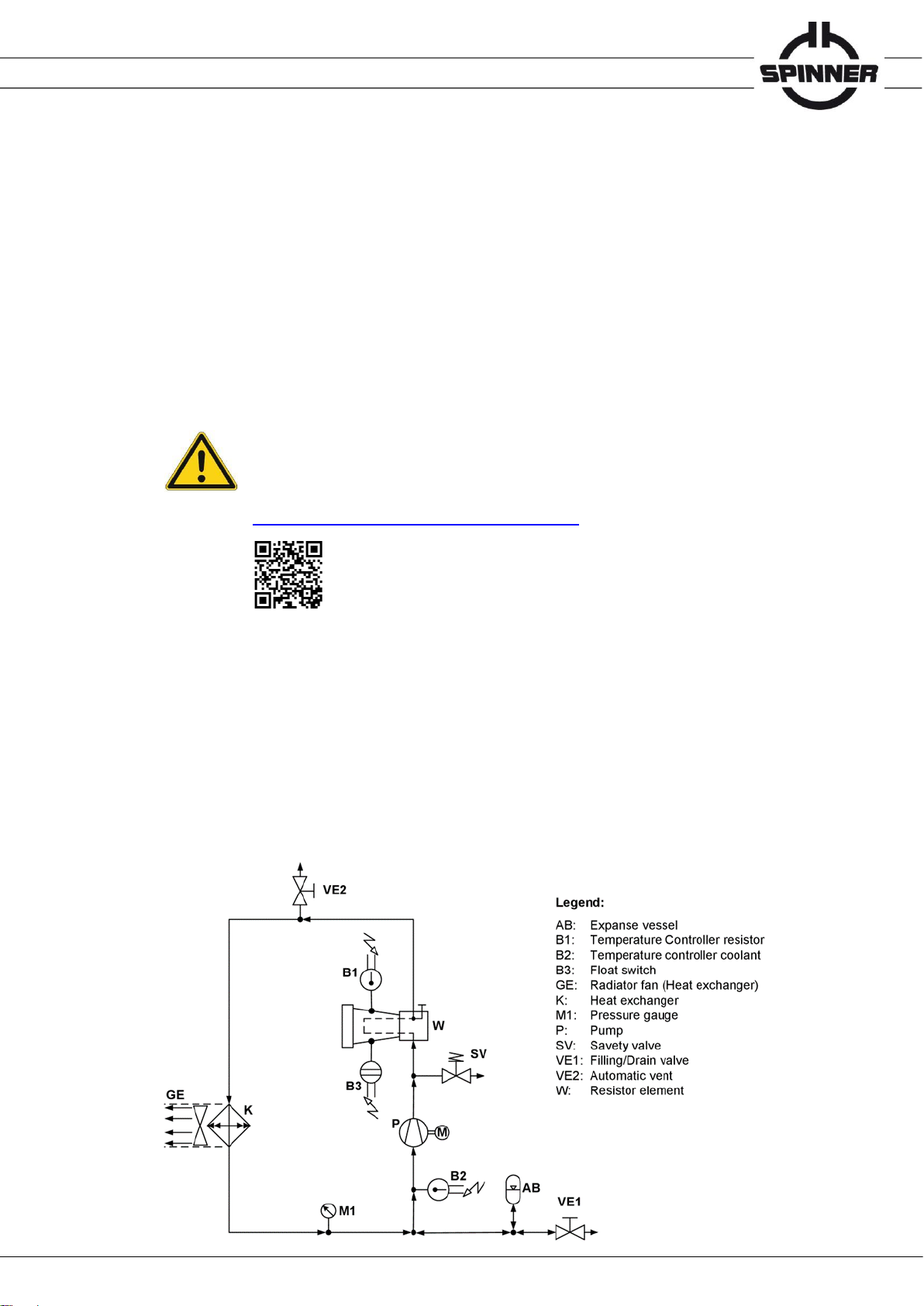
4.4 Coolant circuit of the liquid cooling system
A pressurized closed cooling circuit with radiator fan is used for heat release. The coolant is pumped
through the resistor element W and the heat exchanger K by means of the coolant pump P.
The expanse vessel AB is added due to the thermal expansion of the coolant. The outer surface
temperature of the resistor element and the coolant temperature are monitored by means of the
temperature controllers B1 and B2. Leakage from the resistor element is monitored by the float
switch B3.

Data subject to change without notice │ 10086219│ Issue B│ 2023-09-28
www.spinner-group.com
9 / 27
4.5 Interlock loop
The internal interlock loop for protection of the SmartLoad consists of a programmable logic controller
(PLC), temperature controllers, float switch and signal contacts. The logic of the PLC combines all
seven sensory inputs like switches connected in series to control the interlock loop, which is closed
during normal operation of the SmartLoad. Any open switch shuts down all transmitters connected to
the interlock loop.
•The temperature controller B1 opens at resistor temperatures above 260 °C. After opening the
interlock at 260 °C the load element needs to cool down to 60 °C before the interlock is closed
again. The overtemperature threshold will be reduced gradually to 190 °C and 120 °C to keep the
load element temperatures in a safe range. Between the interlock open temperature of 120°C and
the interlock close temperature of 60°C unlimited operation is possible. After 6 hours of trouble-
free operation or a power cycle the interlock open threshold will be reset to 260 °C.
•The temperature controller B2 opens at coolant temperatures above 90 °C and closes below
80 °C.
•The float switch B3 opens when it detects coolant leaks.
•The protection function of the frequency inverter VFD1 for the coolant pump P opens at coolant
pump motor overload.
•The protection function of the frequency inverter VFD2 for the ventilator GE opens at ventilator
motor overload.
•The main switch interlock is open in power off position of the main switch.
•The radiator fan interlock is open if the connector J3.1 is unplugged.
WARNING
Electric shock hazard
Electric shock can cause severe burns and fatal injuries.
The interlock loop must be de-energized during J2 plugging.
Do not use the interlock loop for personal protection
Schematic diagram of the switching status during normal operation:
The internal interlock loop complies with the requirements for Electrical energy Source class 1 (ES1
type according to IEC 62368-1, safe separation, proof voltage resistance 4 kV ACpk to primary circuit).
The maximum permissible voltage for the interlock loop and to the grounded housing is 42.4 V ACpk
respectively 60 V DC. The power supply must be fully compliant with the ES1 type requirements. The
circuit has to be limited externally to 1 A.
Data subject to change without notice │ 10086219│ Issue B│ 2023-09-28
www.spinner-group.com
10 / 27
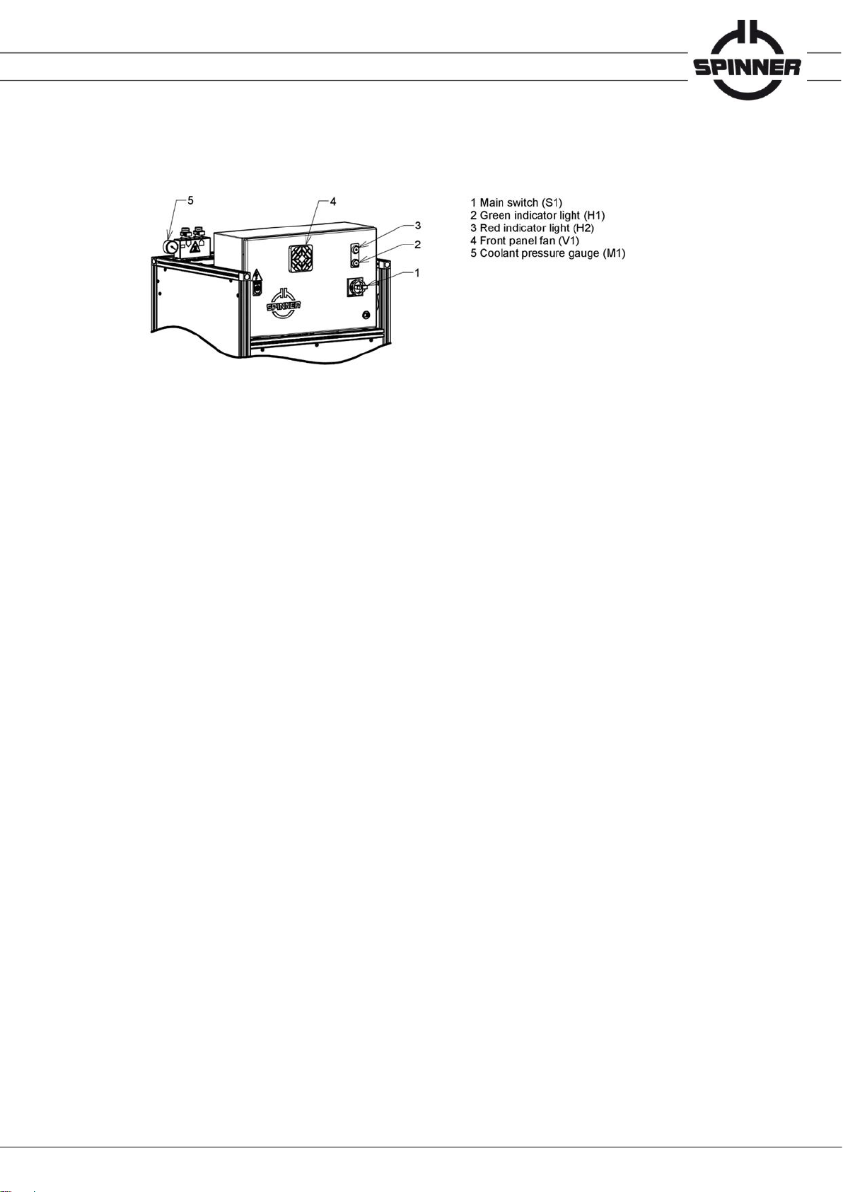
4.6 Operating and display elements
Green indicator light “READY“:
Some 10 seconds after main switch turned on, the green light indicates readiness for operation:
•Mains voltage is connected
•Main switch is turned on
•No fault has been occurred
Red indicator light “WARNING”:
The red light indicates that the interlock loop of the SmartLoad is interrupted. All transmitters
connected properly to the interlock loop are turned off.
The red indicator lamp lights, if the mains voltage is connected and the main switch is turned on and
at least one of the following six conditions is true:
•Resistor element temperature too high
•Coolant temperature too high
•Float switch triggered
•Motor protection VFD1 triggered
•Motor protection VFD2 triggered
•Radiator fan GE connector J3.1 unplugged
Front panel fan
The fan mounted on the front panel of the control cabinet is required for cooling of the frequency
inverters VFD1 and VFD2. The fan runs if the pump is operating at full speed.
4.7 Maintenance cycle
To ensure proper longterm operation of the coolant pump, the PLC activates autonomous
maintenance cycles daily for the duration of a few minutes, refer to “PLC clock time setting” in the
attached PLC manual 10058594.
5 Storage
Keep dry and avoid exposure to sudden temperature changes to prevent condensation.
Environmental conditions for storage are specified in the attached data sheet 10086250.
Do not unpack until immediately prior to installation.
NOTICE Do not remove any connector protection cap until immediately prior to installation to
avoid formation of dust and scratches on sensitive RF contact surfaces.
Environmental conditions for storage refer to attached data sheet TD-00060

Data subject to change without notice │ 10086219│ Issue B│ 2023-09-28
www.spinner-group.com
11 / 27
6 Transportation
CAUTION
Crushing Hazard
The SmartLoad is heavy. Crushing or falling may cause injuries.
Use suitable lifting gear approved to carry at least 200 kg.
Do not stand below the SmartLoad.
To ensure stability, keep the product in the supplied transport packaging until
immediately prior to installation.
Do not lift the SmartLoad at the RF connector.
Do not stress the pressure gauge and the control cabinet.
Do not stress the tubes and the cable of the heat exchanger.
Safety shoes and hardhat are required.
NOTICE Environmental conditions for transportation refer to attached data sheet TD-00060
7 Installation
Before you start, ensure to read and understand the section safety messages and
in particular chapter 1 "Safety" of this product manual. Only electrically skilled
persons should install SPINNER SmartLoads in accordance with the nationalsafety
and accident prevention regulations.
Failure to observe could result in death orserious injury.
Data subject to change without notice │ 10086219│ Issue B│ 2023-09-28
www.spinner-group.com
12 / 27
7.1 Mechanical installation
WARNING
Crushing Hazard
Falling objects may cause death and serious injury.
The SmartLoad is heavy. Use suitable lifting gear only. The lifting gear must be
approved to carry at least 200 kg.
Do not lift the SmartLoad at the RF connector.
Do not stress the expanse vessel and the control cabinet.
Use suitable fasteners if mounted in an elevated position.
Safety shoes are required. If it is necessary to stand below the SmartLoad during
installation, safety shoes and hardhat are required.
WARNING
Electric shock hazard
Electric shock can cause severe burns and fatal injuries.
Do not install and operate the SmartLoad in environmental conditions beyond the
specifications given in the attached data sheet TD-00060. The SmartLoad is
designed for indoor application on operating sites with limited access only.
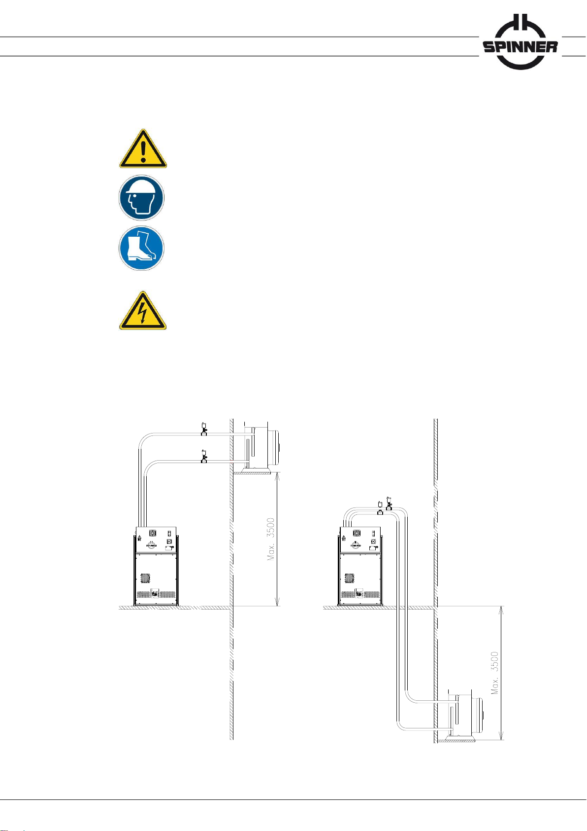
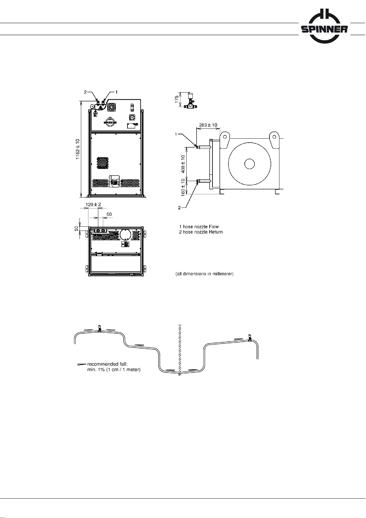
•Define mounting positions of the SmartLoad indoor unit and the external heat exchanger unit
according to the instructions given below. The supplied hoses and connection cable allow a
maximum distance of 10 meters between both units. The automatic vents must be mounted at the
highest point of the cooling circuit, one each in flow and return. From the automatic vents install
the hoses monotonously falling without any upturns to both units.
(all dimensions in millimeter)

Data subject to change without notice │ 10086219│ Issue B│ 2023-09-28
www.spinner-group.com
13 / 27
•The SmartLoad indoor unit must be installed on a flat and solid ground with bearing capacity
higher than 100 kg to ensure stability. The front panel and main switch need to be easily
accessible. Do not install the SmartLoad indoor unit on escape routes or corridors.
•Use the 12 mm mounting holes of the supplied 4 mounting brackets to bolt the SmartLoad indoor
unit with suitable screws to the floor or a support structure. The recommended mounting position
of the adjustable brackets is given below:
•Use all 4 mounting holes of the external heat exchanger to fix it with suitable screws to the floor,
or with fasteners, (e.g. wall hanger supports lengths 640 mm, refer to chapter “Accessories”) and
screws to a wall or support structure with bearing capacity higher than 70 kg.
NOTICE Ensure unobstructed air circulation to avoid overheating.
Free space on the suction side is required.
Y Y
Slot nut
swivelling
with spring sheet
(all dimensions in millimeter)
Y-Y
X X
X-X
Data subject to change without notice │ 10086219│ Issue B│ 2023-09-28
www.spinner-group.com
14 / 27
•Use the supplied hoses and clamps to connect flow and return nozzles of SmartLoad indoor unit
and the external heat exchanger. Recommended clamp torque is 5 Nm.
•The automatic vents must be mounted at the highest point of the cooling circuit, at least one each
in flow and return. When laying hoses with several peaks, a valve must be fitted at each peak.
Data subject to change without notice │ 10086219│ Issue B│ 2023-09-28
www.spinner-group.com
15 / 27
7.2 Electrical installation
WARNING
Electric shock hazard
Electric shock can cause severe burns and fatal injuries.
Before you start ensure to disconnect your entire system from the power supply.
Utilize appropriate devices and methods to prevent accidental energizing.
WARNING
High leakage current
Connect at least 10 mm² PE conductor permanently to separate PE terminal before
connecting mains connector.
WARNING
Radio Frequency Hazard
Radio Frequency Power can cause burns, eye injuries and electrical shock.
Before connecting the RF cable, ensure to disconnect your entire system from the
power supply. Utilize appropriate devices and methods to prevent accidental
energizing.
NOTICE
To avoid overheating caused by RF overload ensure to connect all relevant
transmitters to the interlock system of the SmartLoad prior to commissioning.
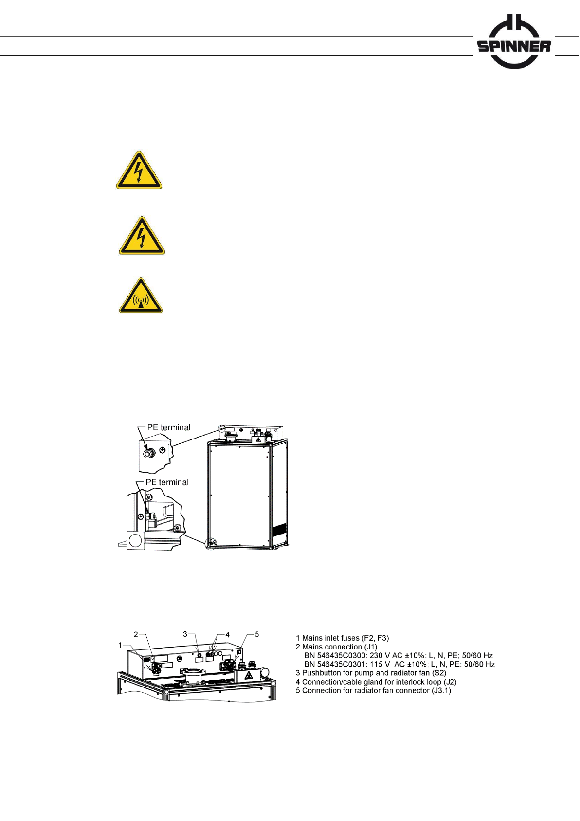
•Connect a PE conductor of at least 10 mm² with cable lug permanently to marked separate PE
terminal, either at the top of the switch cabinet (M8 screw) or at the bottom on the rear of the
frame (M6 screw), before connecting any other wire.
•Connect the radiator fan of the external heat exchanger via J3.1 to the SmartLoad indoor unit.
Cut the cable to the required length, if applicable. The insert of the cable connector can be turned
180 degrees to change the position of the cable inlet. The pin assignment is given in the circuit
diagram 10085335 for BN 546435C0300 resp. 10085351 for BN 546435C0301.
Data subject to change without notice │ 10086219│ Issue B│ 2023-09-28
www.spinner-group.com
16 / 27
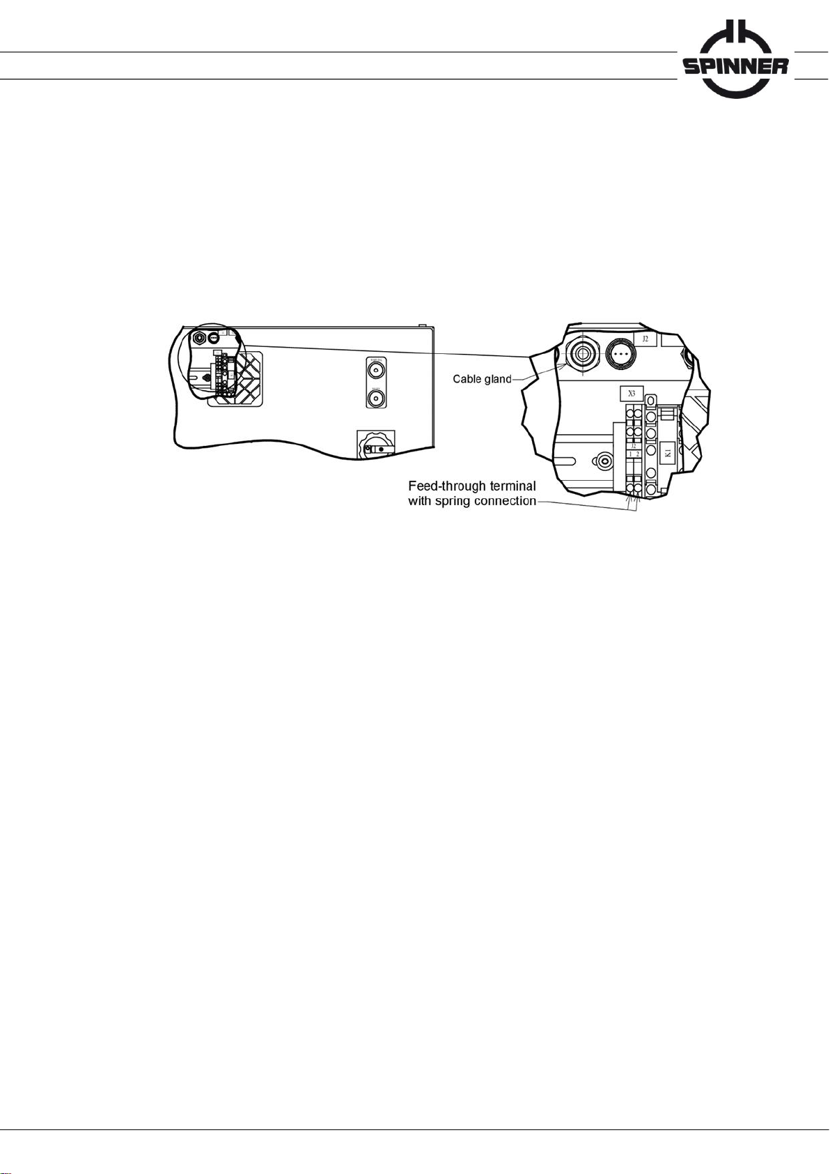
•Connect the interlock loop:
Option 1:
Mount the supplied interlock loop connector on a suitable cable and attach the connector to the
two-pole screw locking IEC 60130-9 port on the rear side of the control box.
Option 2:
Alternatively use the cable gland on the rear side of the control box to run the interlock cable to
the terminals inside the control box in accordance with the attached circuit diagram 10085335 for
BN 546435C0300 resp. 10085351 for BN 546435C0301. Push a screwdriver into the rectangular
opening of the clamp, insert the wire into the round opening and then pull out the screwdriver.
Check proper function of the interlock system prior to commissioning. Do not use the interlock
loop for personal protection.
The maximum permissible voltage for the interlock loop and to the grounded housing is
42.4 V ACpk respectively 60 V DC. The power supply must be fully compliant with the ES1 type
requirements according to IEC 62368-1. The circuit has to be limited externally to 1 A.
•Mount suitable mains connector to the supplied IEC 60320-1 C19 socket power cord
according to the attached circuit diagram.
Mains connector requirements:
BN 546435C0300 230 V AC, 50 Hz to 60 Hz, 10 A, 3x 2.5 mm²
BN 546435C0301 115 V AC, 50 Hz to 60 Hz, 16 A, 3x 2.5 mm²
Alternatively, a standard mains cable with a cross-section of 3x 2.5 mm² and an IEC
60320-1 C19 socket can be used.
Use an easily accessible socket located close to the SmartLoad for mains connection.
Connect the SmartLoad only to TN networks (L, N, PE):
BN 546435C0300 230 V AC, 50 Hz to 60 Hz
BN 546435C0301 115 V AC, 50 Hz to 60 Hz.
•Connect RF using connectors according to IEC 339 only.
•Relieve all connections to the SmartLoad from any bending torque, e.g. caused by heavy cables
or assemblies.
•Check sufficiently dimensioned PE-connection and PE-continuity prior to commissioning.
•Check functioning of the interlock loop by turning the main switch (S1) into the off position.
NOTICE We recommend placing lightning rods close to the external heat exchanger to
ensure lightning protection.

Data subject to change without notice │ 10086219│ Issue B│ 2023-09-28
www.spinner-group.com
17 / 27
7.3 Filling of the coolant circuit
Observe the attached safety data sheet of the coolant when filling up,
emptying or deaerating the liquid cooling system or disposing of the coolant.
Wear eye protection
Wear safety gloves
The cooling circuit with a capacity of approx. 26 l shall be filled via the G ¾” filling nozzle of the
SmartLoad indoor unit by means of a separately available filling pump set, refer to chapter
“Accessories”. If the filling pump set is not available, the included nozzle adaptor to 13 mm hose can
be used to an existing filling set.
NOTICE Use only the coolant ANTIFROGEN N, SPINNER BN 39463A (20 l canister), 2 pcs
required.
•Attach hose to the filling nozzle with G ¾” external thread at the expansion vessel.
•Insert suction hose of the filling pump into coolant canister.
•Open filling nozzle ball valve.
•Open the ball valve of the automatic vents. Turn the cap of vent anticlockwise 360 degrees to
open the vent.
•Operate filling pump until the coolant gauge pressure reaches 1.0 bar.
•Close filling nozzle ball valve and disconnect pump.
•Close the ball valve of the automatic vents. Turn the cap of vent clockwise 360 degrees to
close the vent.
•Deaerate the cooling circuit, refer to chapter 9.2.
NOTICE Pump must not run dry.
NOTICE Pump must run evenly without disturbing noise. Faultless functioning of the
SmartLoad unit can only be guaranteed, if the cooling system is deaerated properly.
Repeat deaeration if the pump does not run evenly without disturbing noise.
The coolant must be free of any bubbles.
Cap
Vent
Ball valve
Venting screw
Coolant drain screw
Gauge pressure
Filling/Drain nozzle

Data subject to change without notice │ 10086219│ Issue B│ 2023-09-28
www.spinner-group.com
18 / 27
8 Commissioning and normal operation
Before you start, ensure to read and understand the section safety messages
and in particular chapter 1 "Safety" of this product manual. Only electrically skilled
persons may commission and operate SPINNER SmartLoads in accordance with
the national safety and accident prevention regulations.
Failure to observe could result in death or serious injury.
CAUTION
Hot surface
The resistor element heats up during normal operation and may cause burns.
Do not remove any covers.
Do not touch the resistor element before cooled down.
For latest maintenance procedures and updates, please check our website https://www.spinner-
group.com/en/products/smart-load-service regularly at least every six months and register your
product there.
Before applying RF power to the SmartLoad electrically skilled persons have to ensure:
•Proper connection of all system connectors.
•Proper functioning of the interlock loop, all relevant transmitters must be connected to the
interlock system of the SmartLoad.
•Correct coolant pressure (refer to chapter 7.3).
•Completely deaerated cooling circuit (refer to chapter 9.2).
•Check the rotational direction of heat exchanger radiator fan. The radiator fan must run in
direction of arrow. If radiator fan runs in opposite direction, interchange two phases at
radiator fan cable.
•Unobstructed air circulation; do not cover the ventilation openings.
•The SmartLoad is switched on, the green indicator lights.
•The clock in the PLC for activation of the maintenance cycle is adjusted correctly.
Open the switch cabinet and set, if applicable, the clock time and date as described in the attached
PLC manual 10058594.
During operation, the pump and fan switch on at intervals. The length of the intervals depends on the
RF power applied and the ambient temperature.
Data subject to change without notice │ 10086219│ Issue B│ 2023-09-28
www.spinner-group.com
19 / 27
9 Maintenance
Before you start, ensure to read and understand the section safety messages and in
particular chapter 1 "Safety" of this product manual. Only trained persons may clean
SPINNER SmartLoads in accordance with the national safety and accident
prevention regulations. Failure to observe could result in death or serious injury.
WARNING
Electric shock hazard
Electric shock can cause severe burns and fatal injuries.
Before you start ensure to disconnect your entire system from the power supply.
Utilize appropriate devices and methods to prevent accidental energizing.
The mains connector must be de-energized during plugging.
Do not use any liquids for cleaning.
WARNING
Entanglement Hazard
The ventilators may entangle hair, clothing or jewelry causing death or serious injury.
Wait until all rotating parts have stopped.
Wear a hair net and close-fitting clothing.
CAUTION
Hot surface
The resistor element heats up during normal operation and may cause burns.
Do not remove any covers shortly after use of the SmartLoad.
Do not touch the resistor element before cooled down
Detailed maintenance descriptions and videos are available at:
https://www.spinner-group.com/en/products/smart-load-service
Maintenance schedule:
Weekly:
•Check around the SmartLoad for coolant leakage. Check the cooling circuit for leaks.
•The coolant pressure (nominal range 0.75 to 1.1 bar), refer to chapter 7.3 for correction.
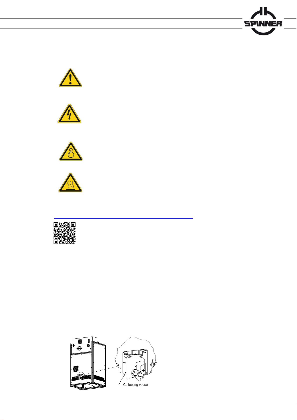
•The tightness of the pump. Coolant leaks of a few drops per day and thus a few drops in the
collecting vessel are normal and cannot be avoided due to the pump design. If the coolant
level in the collecting vessels exceeds some 10 mm, check the pump and operating pressure.
Check the coolant level in the collecting vessel, the coolant pressure and the coolant circuit for
leakage daily, if the coolant gauge pressure is within the nominal range (0.75 to 1.1 bar) and
no reason for the leakage can be found. Contact the SPINNER service in case of permanently
increased coolant drain.

Data subject to change without notice │ 10086219│ Issue B│ 2023-09-28
www.spinner-group.com
20 / 27
•Press pump button on back of electrical cabinet for a few seconds to activate pump for check.
Check again for leakage.
Monthly:
•Verify the unobstructed air circulation of the heat exchanger. Remove dust or dirt from the
heat exchanger with compressed air or a soft brush.
Quarterly:
•Verify installed software is the most current revision, refer to https://www.spinner-
group.com/en/products/smart-load-service
Annually:
•Perform functional test on all reject SmartLoads. See video "Functional Test" for detailed
instructions, refer to https://www.spinner-group.com/en/products/smart-load-service
•Check if the filter on fan of electrical cabinet is saturated with dusk. If so, it can be vacuum
cleaned or shook out and used again. In dusty environments, we recommend cleaning the
filter regularly to avoid decreasing fan performance.
•Check glycol concentration, refer to chapter 9.3.
Every 4 years:
•Exchange coolant, refer to chapter 9.4.
9.1 PLC clock time setting
Before you start, ensure to read and understand the section safety messages and
in particular chapter 1 "Safety" of this product manual. Only electrically skilled
persons may open the control box of SPINNER SmartLoads and set the PLC
clock time in accordance with the national safety and accident prevention
regulations.
Failure to observe could result in death or serious injury.
Details are given in the attached separate PLC manual 10058594.
9.2 Deaeration of the cooling circuit
Before you start, ensure to read and understand the section safety messages and in
particular chapter 1 "Safety" of this product manual. Observe the material data sheet
of the coolant. Only qualified personnel may deaerate SPINNER SmartLoad units in
accordance with the national safety and accident prevention regulations.
Failure to observe could result in death or serious injury.
WARNING
Electric shock hazard
Electric shock can cause severe burns and fatal injuries.
Before you start ensure to disconnect your entire system from the power supply.
Utilize appropriate devices and methods to prevent accidental energizing.
This manual suits for next models
1
Table of contents
Other Spinner Industrial Equipment manuals

Popular Industrial Equipment manuals by other brands

GFA
GFA ELEKTROMAT SI 25.10-30,00 installation instructions

Quincy
Quincy QOCS 25 Instruction book

parr
parr 1108 Operating instructions manual

AGF
AGF TESTanDRAIN Valve Repair Kit Repair instructions

SSI SCHAEFER
SSI SCHAEFER Cuby Assembly and operating manual

Sentry
Sentry Saf-T-Vise STV-HP1 Original instructions


PARKSON
PARKSON Hycor ThickTech RDT400 Installation, operation & maintenance manual

Southworth
Southworth SR-44 Series owner's manual

Siemens
Siemens FLENDER FLUDEX Series operating instructions

POSTPROCESS
POSTPROCESS DECI-SR007-02 user manual

Clemco
Clemco Zero BNP 6012 manual

ABB
ABB A165-L32 Operation manual