Spirit XT685 User manual

XT685 Treadmill
OWNER’S MANUAL


3
TABLE OF CONTENTS
5 IMPORTANT SAFETY INSTRUCTIONS
6 IMPORTANT ELECTRICAL INSTRUCTIONS
7 IMPORTANT GROUNDING INSTRUCTIONS
8 IMPORTANT OPERATION INSTRUCTIONS
9 PRODUCT REGISTRATION
10 XT685 ASSEMBLY INSTRUCTIONS
17 CONSOLE OPERATION
25 PROGRAMMABLE FEATURES
37 USING HEART RATE TRANSMITTER
38 USING THE SPIRIT FIT APP
41 GENERAL MAINTENANCE
46 MANUFACTURER’S LIMITED WARRANTY
Thank you for purchasing our product, please save these instructions. Please do not perform or attempt any
customizing, adjustments, repair or maintenance that is not described in this manual.

4
Congratulations on your new treadmill and welcome to the Spirit Fitness family!
Thank you for your purchase of this quality treadmill from Spirit Fitness.Your new treadmill was manufactured by one of the
leading tness manufacturers in the world and is backed by one of the most comprehensive warranties available. Through your
dealer, Spirit Fitness will do all we can to make your ownership experience as pleasant as possible for many years to come.
If not purchased direct from Spirit Fitness, the local dealership where you purchased this treadmill is your administrator for
all Spirit Fitness warranty and service needs. Their responsibility is to provide you with the technical knowledge and service
personnel to make your experience more informed and any difculties easier to remedy.
Please take a moment at this time to record the name of the dealer, their telephone number, and the date of purchase below
to make any future, needed contact easy.We appreciate your support and we will always remember that you are the reason
that we are in business.
Yours in Health,
Spirit Fitness
NAME OF DEALER _____________________________________
DEALER PHONE # _____________________________________
PURCHASE DATE _____________________________________

5
Important Safety Instructions
WARNING
When using an electrical appliance, basic precautions should
always be followed, including the following:
Read all instructions before using this appliance.
DANGER -To reduce the risk of electric shock:
Always unplug this appliance from the electrical outlet
immediately after using and before cleaning.
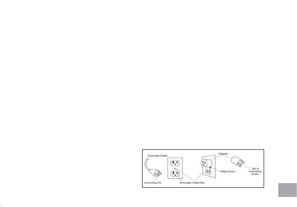
WARNING - To reduce the risk of burns, re, electric
shock, or injury to persons, install the treadmill on a at level
surface with access to a 110-volt, 15-amp grounded outlet
with only the treadmill plugged into the circuit.
DO NOT USE AN EXTENSION CORD UNLESS IT IS A 14AWG OR
BETTER,WITH ONLY ONE OUTLET ON THE END:
To reduce the risk of burns, re electric shock, or injury to
persons:
• An appliance should never be left unattended when
plugged in. Unplug from outlet when not in use, and
before putting on or taking off parts.
• Do not operate under blanket or pillow. Excessive
heating can occur and cause re, electric shock, or
injury to persons.
• Close supervision is necessary when this appliance
is used by, on, or near children, invalids, or disabled
persons.
• Use this appliance only for its intended use as
described in this manual. Do not use attachments not
recommended by the manufacturer.
• Never operate this appliance if it has a damaged cord
or plug, if it is not working properly, if it has been
dropped or damaged, or dropped into water. Return
the appliance to a service center for examination and
repair.
• Do not carry this appliance by supply cord or use cord
as a handle.
• Keep the cord away from heated surfaces.
• Never operate the appliance with the air openings
blocked. Keep the air openings free of lint, hair, and the
like.
• Never drop or insert any object into any opening.
• Do not use outdoors.
• Do not operate where aerosol (spray) products are
being use or where oxygen is being administered.
• Connect this appliance to a properly grounded outlet
only.
• The appliance is intended for household use.
• This exercise equipment is not intended for use by
persons with reduced physical, sensory or mental
capabilities, or lack of experience and knowledge.
• Keep children under the age of 13 away from this
machine.
SAVE THESE INSTRUCTIONS - THINK SAFETY!
WARNING: This product can expose you to chemicals
including Toluene and Acrylamide which are known to the
State of California to cause cancer and birth defects or
other reproductive harm. For more information go to www.
P65Warnings.ca.gov

6
Fitness Equipment Safety Instructions
• Do not operate equipment on deeply padded, plush or shag carpet. Damage to both carpet and equipment may result.
• Before beginning this or any exercise program, consult a physician. This is especially important for persons over the age
of 35 or persons with pre-existing health conditions.
• Do not attempt to use your equipment for any purpose other than for the purpose it is intended.
• Keep hands away from all moving parts.
• The pulse sensors are not medical devices. Their purpose is to provide you with an approximate measurement in
relation to your target heart rate. Use of a chest transmitter strap (sold separately) is a much more accurate method
of heart rate analysis .Various factors, including the user’s movement, may affect the accuracy of heart rate readings. The
pulse sensors are intended only as exercise aids in determining heart rate trends in general.
• Wear proper shoes. High heels, dress shoes, sandals or bare feet are not suitable for use on your equipment. Quality
athletic shoes are recommended to avoid leg fatigue.
Failure to follow all guidelines may compromise the effectiveness of the exercise experience, expose yourself (and possibly
others) to injury, and reduce the longevity of the equipment.
Important Electrical Instructions
WARNING
NEVER use a ground fault circuit interrupt (GFCI) wall outlet with this treadmill. As with any appliance with a large
motor, the GFCI will trip often. Route the power cord away from any moving part of the treadmill including the elevation
mechanism and transport wheels.
NEVER remove any cover without rst disconnecting AC power. If voltage varies by ten percent (10%) or more, the
performance of your treadmill may be affected. Such conditions are not covered under your warranty. If you suspect the
voltage is low, contact your local power company or a licensed electrician for proper testing.
NEVER expose this treadmill to rain or moisture.This product is NOT designed for use outdoors, near a pool or spa, or in
any other high humidity environment. The operating temperature specication is 40 to 120 degrees Fahrenheit, and humidity
is 95% non-condensing (no water drops forming on surfaces).

7
Circuit Breakers: Some circuit breakers used in homes are not rated for high inrush currents that can occur when a
treadmill is rst turned on or even during use. If your treadmill is tripping the house circuit breaker (even though it is
the proper current rating) but the circuit breaker on the treadmill itself does not trip, you will need to replace the home
breaker with a high inrush type. This is not a warranty defect. This is a condition we as a manufacture have no ability to
control. This part is available through most electrical supply stores. Examples: Grainger part # 1D237, or available online at
www.squared.com part #QO120HM.The electrical outlet used should have a dedicated 15 amp circuit breaker.
Grounding Instructions
This product must be grounded. If the your equipment should malfunction or breakdown, grounding provides a path
of least resistance for electric current, reducing the risk of electric shock. This product is equipped with a cord having an
equipment-grounding plug.The plug must be plugged into an appropriate outlet that is properly installed and grounded in
accordance with all local codes and ordinances.
DANGER - Improper connection of the equipment-grounding conductor can result in a risk of electric shock. Check with a
qualied electrician or serviceman if you are in doubt as to whether the product is properly grounded. Do not modify the plug
provided with the product if it will not t the outlet; have a proper outlet installed by a qualied electrician.
This product is for use on a nominal 110-volt dedicated circuit, and has a grounding plug that looks like the plug illustrated
below. A temporary adapter that looks like the adapter illustrated below may be used to connect this plug to a 2-pole
receptacle as shown below if a properly grounded outlet is not available. The temporary adapter should be used only until
a properly grounded outlet, (shown below) can be installed
by a qualied electrician. The green colored rigid ear-lug, or
the like, extending from the adapter, must be connected to
a permanent ground such as a properly grounded outlet
box cover. Whenever the adapter is used, it must be held in
place by a metal screw.

8
Important Operation Instructions
• NEVER operate this treadmill without reading and completely understanding the results of any operational change you
request from the computer.
• Understand that changes in speed and incline do not occur immediately. Set your desired work level on the computer
console and release the adjustment key.The computer will obey the command gradually.
• NEVER use your treadmill during an electrical storm. Surges may occur in your household power supply that could
damage treadmill components. Unplug the treadmill during an electrical storm as a precaution.
• Use caution while participating in other activities while walking on your treadmill; such as watching television, reading,
etc.These distractions may cause you to lose balance which may result in serious injury.
• Do not use excessive pressure on console control keys. They are precision set to function properly with little nger
pressure
Safety Tether Cord
A safety tether cord is provided with this unit. It is a simple magnetic design that should be used at all times. It is for your
safety should you fall or move too far back on the tread-belt. Pulling this safety tether cord will stop tread-belt movement.
To Use:
1. Place the magnet into position on the round metal portion of the console control head.Your treadmill will not start
and operate without this. Removing the magnet also secures the treadmill from unauthorized use.
2. Fasten the plastic clip onto your clothing securely to assure good holding power.
Note: The magnet has strong enough power to minimize accidental, unexpected stopping. The clip should be attached
securely to make certain it does not come off. Be familiar with its function and limitations.The treadmill will stop,
depending on speed, with a one to two step coast anytime the magnet is pulled off the console. Use the Stop / Pause
switch in normal operation.

9
Record Your Serial Number
Please record the serial number of this tness product in the space provided below.
Serial Number:
Register Your Purchase
The self-addressed product registration card must be completed in full and
returned to Spirit Fitness. You can also go to https://www.spirittness.com/
residentialwarrantyregistration.html under the Support tab to register online.
Serial Number Location

10
XT685 PRE ASSEMBLY
UNPACKING
1. Cut the straps, then lift the box over the unit and unpack.
2. Carefully remove all parts from the carton and inspect for any damage
or missing parts. If parts are damaged or missing, contact your dealer
immediately.
3. Locate the hardware package. Remove the tools rst. Remove the hard-
ware for each step as needed to avoid confusion. The numbers in the
instructions that are in parenthesis (#) are the item number from the
assembly drawing for reference.
TOOLS INCLUDED:
L Allen Wrench
Phillips Head Screwdriver
Combination M5 Allen Wrench
& Phillips Head Screw Driver
PARTS INCLUDED:
1 Main Frame
2 Uprights
2 Console Mast Covers
2 Frame Base Covers
1 Console
1 Deck
1 Audio Cable
1 Beverage Holder
1 Power Cord
1 Hardware Kit

11
SPEAKERS
CONSOLE
UPRIGHTS
BELT
HANDLES
END CAPS
MOTOR COVER
SIDE RAILS
CONSOLE FAN

12
XT685 STEP ONE
HARDWARE FOR STEP 1
PART TYPE DESCRIPTION QTY
100 BOLTS 5/16” X 3/4” 4
124 CURVED WASHERS Ø8 X 23 X 1.5T 4
123 BOLTS 3/8” X 2-1/2” 6
79 FLAT WASHER Ø3/8” × Ø19 × 1.5T 6
86 SPRING WASHER Ø10 × 2.0T 6
1. Gather HARDWARE FOR STEP 1.
2. Slide the UPRIGHT COVERS (L 52, R 53) onto
the LEFT AND RIGHT UPRIGHTS (4, 5).
3. Slide the CONSOLE MAST SIDE CAPS (L 98,
R99) onto the LEFT AND RIGHT UPRIGHTS (4,
5) under the Upright Covers.
4. Connect the LOWER COMPUTER CABLE (33)
to the MIDDLE COMPUTER CABLE (32). Be sure
not to pinch the cable or damage may occur.
5. Insert the LEFT AND RIGHT UPRIGHTS into the
MAIN FRAME (1) and use the COMBINATION
WRENCH AND PHILLIPS SCREW DRIVER
(103) to secure 4 BOLTS (100) and 4 Curved
Washers (124) into place.
6. Use the L-SHAPED ALLEN WRENCH (104) to
tighten the LEFT AND RIGHT GUSSET (7, 8)
with 6 Bolts (123), 6 FLAT WASHERS (79), and 6
SPRING WASHERS (86).

13
XT685 STEP TWO
HARDWARE FOR STEP 2
PART TYPE DESCRIPTION QTY
127 PHILLIPS HEAD SCREWS M5 X 10MM 4
1. Gather HARDWARE FOR STEP 2.
2. Install the CONSOLE MAST SIDE CAP (L 98, R
99) onto the MAIN FRAME (1) and secure it using
4 SCREWS (127) by using the COMBINATION
WRENCH AND PHILLIPS SCREW DRIVER
(103).

14
XT685 STEP THREE
HARDWARE FOR STEP 3
PART TYPE DESCRIPTION QTY
91 BOLTS 3/8” X 1-3/4” 4
86 SPLIT WASHER Ø10 × 2.0T 4
1. Gather HARDWARE FOR STEP 3
2. Connect the SPEED ADJUSTMENT
SWITCH W/ CABLE (37) with the UPPER
SPEED CABLE (34).
3. Connect the INCLINE ADJUSTMENT
SWITCH W/ CABLE (38) with the UPPER
INCLINE CABLE (35).
4. Connect the MIDDLE COMPUTER CABLE
(32) to the UPPER COMPUTER CABLE
(31).
5. Be sure not to pinch any of the cables or
damage may occur to the system.
6. Insert the CONSOLE ASSEMBLY (36)
onto the RIGHT AND LEFT UPRIGHTS
(4, 5) and secure with 4 BUTTON HEAD
SOCKET BOLTS (91) and 4 SPLIT
WASHERS (86). Use the ALLEN WRENCH
(107) to tighten.
91
91

15
XT685 STEP FOUR
HARDWARE FOR STEP 4
PART TYPE DESCRIPTION QTY
125 SHEET METAL SCREWS 3.5 × 16MM 8
1. Gather HARDWARE FOR STEP 4.
2. Slide CONSOLE MAST COVER RIGHT
AND LEFT (53, 52) up the uprights. Secure
them with 8 SHEET METAL SCREWS
(125) using the PHILLIPS HEAD SCREW
DRIVER (126).

16
XT685 STEP FIVE
HARDWARE FOR STEP 5
PART TYPE DESCRIPTION QTY
100 BOLTS 5/16” X 3/4” 4
1. Gather HARDWARE FOR STEP 5.
2. Place the HANDRAIL SUPPORT
(3) between the LEFT AND RIGHT
UPRIGHTS (5, 4) and use the
COMBINATION ALLEN WRENCH &
PHILLIPS HEAD SCREW DRIVER (103)
to tighten 4 BUTTON HEAD SOCKET
BOLTS (100).
3. Place the BEVERAGE HOLDER (120) onto
the HANDRAIL SUPPORT (3).

17
XT685 CONSOLE OPERATION
Ten innovative
programs offer a
variety of work-outs
Heart Rate % Profile
Easy-Touch
Control Keys
Muscle
Activation Profile
Swivel Fan to
keep you cool
Integrated Speakers
for MP3 Player
Large LCD with
scrolling feedback
and scrolling
message center
Select Keys Control
Speed & Incline
Audio Jack

18
FEATURES
Handrail Adjustments
The XT685 treadmill allows you to make speed and incline changes on the side handrails. You can also
choose to turn these off if you frequently hold on to these rails. This is achieved by pressing the disable
button on the right side of the lower portion of the console.
Select Speed and Incline Buttons
You are able to set your speed and incline settings quickly by using the Select Keys on the console. Just
press either Speed or Incline, then select either 2, or 3 digits and the treadmill will automatically adjust
to that value. This saves time because you don’t have to press and hold or hold a button down until
reaching the desired value. The maximum value you may input for speed is 12.0 mph or 18.0 kmph and
incline 15.0%
Examples: Press the Select Incline button, then 1, 0 = Incline Level 1.0
Press the Select Incline button, then 3, 5 = Incline Level 3.5
Press the Select Speed button, then 8, 0 = 8.0 mph or kmph
Press the Select Speed button, then 0, 8 = 0.8 mph or kmph
CONSOLE
Muscle Activation Figure
There is an anatomical gure located at the top of the console. This gure will light all areas that are
activated when using the treadmill. These will light up during any of the programs. You can control
which muscles are activated by changing the incline and swinging your arms. The pre-set programs will

19
determine which lower body muscles will be activated by automatically adjusting the incline. Generally
the following guidelines hold true:
• The upper body LED’s will light any time your hands aren’t in contact with the pulse grip sensors
• The lower body lights will activate in three degrees of engagement: Green represents minimal muscle
involvement, Amber represents medium involvement, and Red represents full or heavy activation.
• 0-4.5% Elevation: even muscle distribution, all four muscle groups will be Amber
• 5-15% Elevation: Quads are Amber and Glutes, Hamstrings, and Calves are Red
Message Center
The console will display Pace, Calories burned, Time (elapsed or countdown), Distance traveled, Pulse,
Speed, Incline, Program Name, # of Laps completed, and Segment Time.There is also a Speed & Incline
prole graph that lets you see how hard you have worked and how challenging the upcoming segments
will be.
Heart Rate % Profile
The console LCD screen will display your current heart rate anytime a pulse is detected.The Bar
Graph, located to the right of the LCD screen, will show your current heart rate % in relation to
your projected maximum heart rate, which is determined by your age that you entered during the
programming phase of any of the 10 programs. The signicance of the bar graph colors are as follows:
• 50-60% of maximum is Amber
• 65-80% of maximum is Amber and Green
• 85-90% or more is Amber, Green, and Red

20
Dot Matrix Center Display
Twenty columns of boxes (10 high) indicate each segment of a workout.The boxes only show an
approximate level (resistance) of effort. They do not necessarily indicate a specic value - only an
approximate percent to compare levels of intensity. In Manual Operation the resistance dot matrix
window will build a prole “picture” as values are changed during a workout.
The speed and incline proles will display half of the program at one time (10 columns). They will both
scroll right to left.
1/4 Mile Track
The 1/4-mile track (one lap) will be displayed around the dot matrix window. The ashing segment
indicates your progress. Once the 1/4-mile (Metric - 0.4k) is complete this feature will begin again.The
Lap track will move in a counterclockwise direction There is a lap counter in the message window for
monitoring your distance.
Pulse Grip Feature
The Pulse (Heart Rate) window will display your current heart rate in beats per minute during the
workout.You must use both stainless steel sensors on the stationary grips or the heart rate transmitter
chest strap to display your pulse. Pulse value displays anytime the upper display is receiving a Pulse
signal.You may not use the Pulse Grip feature while in Heart Rate Programs.
Note: Refer to Important Safety Instructions (page 3) concerning Pulse Grip operation.
Other manuals for XT685
6
Table of contents
Other Spirit Treadmill manuals

Spirit
Spirit XT175 User manual

Spirit
Spirit XT 600 User manual

Spirit
Spirit 1622775 User manual

Spirit
Spirit CT 900 TFT User manual

Spirit
Spirit XT285 User manual

Spirit
Spirit XT385 User manual

Spirit
Spirit CT 800 User manual

Spirit
Spirit 1613285 XT285 User manual

Spirit
Spirit CT 800 User manual

Spirit
Spirit CT 800 User manual

Spirit
Spirit CT900 User manual

Spirit
Spirit SPT0042 User manual

Spirit
Spirit F7500 Instruction Manual

Spirit
Spirit Z8 User manual

Spirit
Spirit CT 900 LED User manual

Spirit
Spirit XT 600 User manual

Spirit
Spirit XT285 User manual

Spirit
Spirit F7600 Instruction Manual

Spirit
Spirit Z900 User manual

Spirit
Spirit XT385 User manual