Spirit XT685ENT User manual

XT685ENT TREADMILL
Scan to quickly and easily
register your new Spirit
Fitness machine.
If you require assistance or are
experiencing issues with your
Spirit Machine, please contact
customer care for additional help.
1-800-258-8511
questions@spirittness.com
Online Support
Warranty Registration
XT685ENT_685523_OM_20231019

1

2
Table of Contents
Product Registration .........................................................3
Warning / Safety Instructions
Product Labels.....................................................................4
Warnings, Compliance, and Notes.................................5
Safety Instructions ............................................................ 6
Electrical Safety...................................................................7
Grounding & Location Requirements.......................... 8
Parts and Assembly
Parts Included ..................................................................... 9
Parts of Your Treadmill................................................... 10
Pre-Assembly ..................................................................... 11
Assembly..............................................................................12
Setting Up Your Unit ........................................................16
Safety Key............................................................................18
Technology and Features
About Your Machine ........................................................19
Console Screen - Overview...........................................20
Console Screen - Touchscreen .....................................21
Using the Spirit+ App...................................................... 22
Features .............................................................................. 23
Touchscreen Operation ................................................. 25
Heart Rate Monitoring
Heart Rate Chest Strap.................................................. 29
Chest Strap Warning.......................................................30
Heart Rate Exertion .........................................................31
Programs
Programs Intro.................................................................. 33
Programs ............................................................................ 34
Maintenance
Maintenance & Care........................................................ 43
Belt & Deck Cleaning....................................................... 47
Exploded View Diagram ................................................48
Parts List.............................................................................49
Warranty & Troubleshooting
Warranty ............................................................................ 53
Troubleshooting............................................................... 56

3
PRODUCT REGISTRATION
WARRANTY REGISTRATION
Use your smartphone to scan the QR code
above to quickly and easily register your
new Spirit Fitness machine.
You can also go to spirittness.com/
warranty under the Support tab to
register online.
Congratulations on your new treadmill, and welcome to the Spirit
Fitness family!
Thank you for your purchase of this quality unit from Spirit Fitness.
Your new unit was manufactured by one of the leading tness
manufacturers in the world and is backed by one of the most
comprehensive warranties available. Through your dealer, Spirit Fitness
will do all we can to make your ownership experience as pleasant as
possible for many years to come.
If not purchased direct from Spirit Fitness, the local dealership where
you purchased this unit is your administrator for all Spirit Fitness
warranty and service needs. Their responsibility is to provide you
with the technical knowledge and service personnel to make your
experience more informed and any diculties easier to remedy.
Please take a moment at this time to record the name of the dealer,
their telephone number, and the date of purchase below to make any
future, needed contact easy. We appreciate your support and we will
always remember that you are the reason that we are in business.
Serial
Number
Date of
Purchase
Dealer /
Place of
Purchase
Version: 7.0
Revision: 10/19/23

4
PRODUCT LABELS
SERIAL NUMBER
(870) 935-1107
SERIAL NUMBER STICKER
This sticker will be found on the rear of the motor cover.
Please record the number below the barcode for the purpose
of registering your treadmill’s warranty.
PROPOSITION 65 WARNING
This sticker will be found on the interior side of
your treadmill’s upright. The State of California
requires us to inform you that this unit was
manufactured using chemicals that could cause
harm with improper use.
SAFETY WARNING STICKER
This sticker will be found on the interior side of
your treadmill’s upright. The same warning can
be found in this manual. Please read and be
aware of the precautions before operating your
unit.
1234 5678 9876

5
WARNINGS, COMPLIANCE AND NOTICES
NOTE: This equipment has been tested and found to comply
with the limits for a Class B digital device, pursuant to Part
15 of the FCC Rules. These limits are designed to provide
reasonable protection against harmful interference in a
residential installation. This equipment generates, uses and
can radiate radio frequency energy and, if not installed and
used in accordance with the instructions, may cause harmful
interference to radio communications. However, there is
no guarantee that interference will not occur in a particular
installation. If this equipment does cause harmful interference
to radio or television reception, which can be determined by
turning the equipment o and on, the user is encouraged to
try to correct the interference by one or more of the following
measures:
1. Reorient or relocate the receiving antenna.
2. Increase the separation between the equipment and
receiver.
3. Connect the equipment to an outlet on a circuit dierent
from that to which the receiver is connected.
4. Consult the dealer or an experienced radio/TV technician for
help.
CAUTION:
• To comply with FCC RF exposure compliance requirements,
a separation distance of at least 20 cm must be maintained
between the antenna of this device and all persons.
• This transmitter must not be co-located or operating in
conjunction with any other antenna or transmitter
This product has been certied to meet the following
standards:
• FCC part 15
• UL
• Bluetooth (with FTMS)
This device complies with part 15 of the FCC Rules.
Operation is subject to the following two conditions: (1)
this device must not cause harmful interference, and (2)
this device must not accept any interference received,
including interference that may cause undesired
operation.

6
SAFETY INSTRUCTIONS
When using an electrical appliance, basic precautions should always be
followed, including the following:
Read all instructions before using this appliance.
DANGER - To reduce the risk of electric shock:
Always unplug this appliance from the electrical outlet immediately after
using and before cleaning.
WARNING - To reduce the risk of burns, re electric shock, or
injury to persons:
1. An appliance should never be left unattended when plugged in.
Unplug from outlet when not in use, and before putting on or taking
o parts.
2. Do not operate under blanket or pillow. Excessive heating can occur
and cause re, electric shock, or injury to persons.
3. This exercise equipment is not intended for use by persons
with reduced physical, sensory or mental capabilities, or lack of
experience and knowledge.
4. Use this appliance only for its intended use as described in this
manual. Do not use attachments not recommended by the
manufacturer.
5. Never operate this appliance if it has a damaged cord or plug, if it is
not working properly, if it has been dropped or damaged, or dropped
into water. Return the appliance to a service center for examination
and repair.
6. Do not carry this appliance by supply cord or use cord as a handle.
7. Keep the cord away from heated surfaces.
8. Never operate the appliance with the air openings blocked. Keep the
air openings free of lint, hair, and the like.
9. Never drop or insert any object into any opening.
10. Do not use outdoors.
11. Do not operate where aerosol (spray) products are being use or
where oxygen is being administered.
12. Connect this appliance to a properly grounded outlet only. See
Grounding Instructions.
13. The appliance is intended for household use.
14. To disconnect, turn all controls to the o position, then remove the
plug from the outlet.
15. Do not operate equipment on deeply padded, plush or shag carpet.
Damage to both carpet and equipment may result.
16. Before beginning this or any exercise program, consult a physician.
This is especially important for persons over the age of 35 or persons
with pre-existing health conditions.
17. Keep hands away from all moving parts.
18. The pulse sensors are not medical devices. Various factors, including
the user’s movement, may aect the accuracy of heart rate readings.
The pulse sensors are intended only as exercise aids in determining
heart rate trends in general.
19. Do not attempt to use your equipment for any purpose other than
for the purpose it is intended.
20. Wear proper shoes. High heels, dress shoes, sandals or bare feet are
not suitable for use on your equipment. Quality athletic shoes are
recommended to avoid leg fatigue.
21. User Weight Limit: 425 lbs.
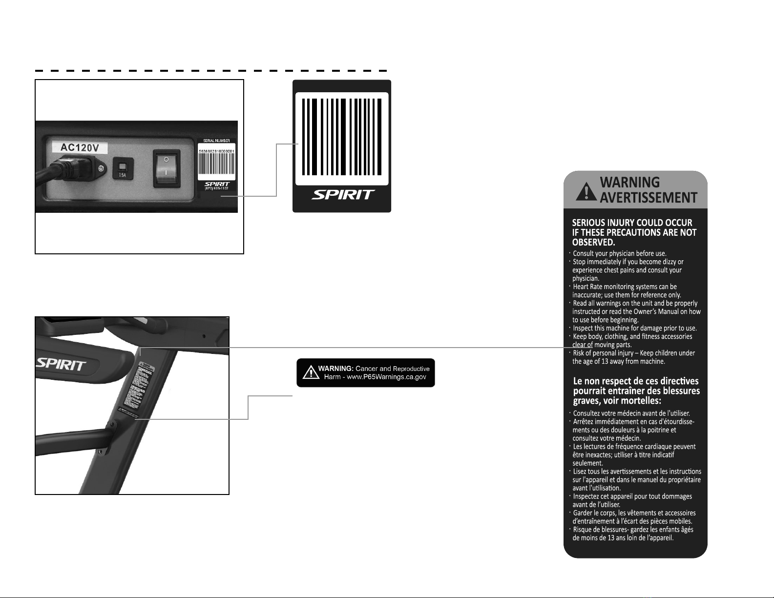
!
!
Please ensure that you review and adhere to the user
weight restrictions and power requirements of your
new machine. Failure to do so may result in serious
injury or damage to your machine.
!

7
ELECTRICAL SAFETY
WARNING!
Route the power cord away from any moving part of the unit
including the elevation mechanism and transport wheels.
NEVER remove any cover without rst disconnecting AC
power. If voltage varies by ten percent (10%) or more, the
performance of your unit may be aected. Such conditions
are not covered under your warranty. If you suspect the
voltage is low, contact your local power company or a
licensed electrician for proper testing.
NEVER expose this unit to rain or moisture. This product
is NOT designed for use outdoors, near a pool or spa, or
in any other high humidity environment. The temperature
specication is 40 degrees C, and humidity is 95%, non-
condensing (no water drops forming on surfaces).
Circuit breakers: Avoid AFCI/GFCI circuit breakers if
possible. These breakers may trip occasionally during
exercise because of the high inrush currents of the unit drive
electronics and motor. This is an issue that aects all unit
brands. New laws in your area may require these breakers.
If you do have these breakers and outlets in your home,
and are experiencing nuisance tripping, you should check if
there are any other devices plugged into the same circuit.
Some examples of devices that may also cause tripping are
uorescent lights with electronic ballasts, coee maker,
space heater, hair drier.
Optimally the unit should be the only device plugged into the
circuit. Our units have surge suppressors built in to help avoid
nuisance tripping. We have tested several AFCI/GFCI breakers
and outlets with our products. Brands we have tested are: Eaton
(Cutler Hammer Series), Leviton (Smart lock pro) and Schneider
Electric (Canadian home series). These breakers do not trip in our
testing, when connected to our units, as long as no other devices
are plugged into the same circuit.
NEVER operate this unit without reading and completely
understanding the results of any operational change you
request from the computer.
Understand that changes in speed and incline do not occur
immediately. Set your desired work level on the computer
console and release the adjustment key. The computer will obey
the command gradually.
NEVER use your unit during an electrical storm. Surges may
occur in your household power supply that could damage unit
components. Unplug the unit during an
electrical storm as a precaution.
Use caution while participating in other activities while walking
on your unit; such as watching television, reading, etc. These
distractions may cause you to lose balance which may result in
serious injury.
Do not use excessive pressure on console control keys. They are
precision set to function properly with little nger pressure.
!

8
GROUNDING & LOCATION REQUIREMENTS
This product must be grounded. If the unit should malfunction or
breakdown, grounding provides a path of least resistance for electric
current, reducing the risk of electric shock. This product is equipped with a
cord having an equipment-grounding plug. The plug must be plugged into
an appropriate outlet that is properly installed and grounded in accordance
with all local codes and ordinances.
DANGER - Improper connection of the equipment-grounding
conductor can result in a risk of electric shock. Check with a qualied
electrician or serviceman if you are in doubt as to whether the product is
properly grounded. Do not modify the plug provided with the product if it
will not t the outlet; have a proper outlet installed by a qualied electrician.
This product is for use on a nominal 110-volt circuit, and has a grounding
plug that looks like the plug illustrated below. A temporary adapter that
looks like the adapter illustrated below may be used to connect this plug
to a 2-pole receptacle as shown below if a properly grounded outlet is
not available. The temporary adapter should be used only until a properly
grounded outlet, (shown below) can be installed by a qualied electrician.
The green colored rigid ear-lug, or the like, extending from the adapter,
must be connected to a permanent ground such as a properly grounded
outlet box cover. Whenever the adapter is used, it must be held in place by a
metal screw.
!
After assembling your treadmill, you’ll need to make sure you’ve
installed it in a safe area.
• We recommend that you leave an area of at least 20in on the
front, and sides of your machine. The front of the unit is where
the motor is located.
• We recommend that you leave an area of at least 6ft behind the
treadmill.
• Install your treadmill in an area where children and pets cannot
access it.
• Always keep the area around your treadmill clear of furniture,
exercise equipment and other debris.
• Do not install your treadmill on deeply padded, plush, or shag
carpet.
20in
20in
20in
6ft
Location Requirements

9
PARTS INCLUDED
TOOLS INCLUDED:
L Allen Wrench
Phillips Head Screwdriver
Combination M5 Allen Wrench & Phillips Head
Screwdriver
PARTS INCLUDED:
1 Main Frame
2 Uprights
2 Console Mast Covers
2 Frame Base Covers
1 Console
1 Deck
1 Power Cord
1 Lubricant
1 Hardware Kit
ASSEMBLY
TOOLS
#126. Phillips Head Screw Driver
#103. M5_ Combination M5 Allen Wrench
& Phillips Head Screw Driver
#104. M6_L Allen Wrench
STEP 1.
STEP 2.
STEP 3.
#79. 3/8" ×19 × 1.5T
Flat Washer (6 pcs)
#123. 3/8” x 2-1/2” Button
Head Socket Bolt (6 pcs)
#86. Ø10 × 2T
Split Washer (4 pcs)
#91. 3/8” x 1-1/2” Button
Head Socket Bolt (4 pcs)
#86..Ø10 × 2.0T
Split Washer (6 pcs)
#100. 5/16” × 3/4" Button
Head Socket Bolt (4pcs)
#124. 8 × 23 × 1.5T
Curved Washer (4 pcs)
#165. M5 x 45L Phillips
Head Screw (4 pcs)
#100. 5/16” x 3/4”
Button Head Socket
Bolt (4 pcs)
#127. M5 × 10L Phillips
Head Screw (4 pcs)
#166. M5 × 25L Phillips
Head Screw (3 pcs)
#125. 3.5 x 16L Sheet
Metal Screw (8 pcs)
STEP 4.

10
PARTS OF YOUR TREADMILL
A. Tablet Holder
B. TouchScreen
C. Accessory tray
D. Console buttons
E. Safety stop key
F. Cup holders
G. Hand pulse sensors
H. Handlebar Speed/Incline
I. Uprights
J. Motor cover
K. Belt
L. Side rails
M. Levelers
N. Transport wheels
A
B
C
D
E
F
G
H
I
J
K
M
L
N

11
PRE-ASSEMBLY
1. Cut the straps, then lift the box over the unit and unpack.
2. Carefully remove all parts from the carton and inspect
for any damage or missing parts. If parts are damaged or
missing, contact your dealer immediately.
3. Locate the hardware package. Remove the tools rst.
4. Remove the hardware for each step as needed to avoid
confusion. The numbers in the instructions that are in
parenthesis (#) are the item number from the assembly
drawing for reference.
Step.1
Step.2
Step.3
Step.4
104
102
101
101
104
102
101
101
52
5
98
4
99
53
33
32
100
103
124
100
124
79
123
104
7
86
79
123
8
86
4
5
1
91
86
4
5
91
104
8
6
36
91
126
165
99
127
1
27
126
127
98
126
166
169
37
170-8
36-18
33-01
36-18
170-7 33
36-18
37-19
37
3
6
37-12
36-16
37-13
37-18
36-17
33-01
100
100
100
3
100
103 54
52
53
125
126
125 125
125

12
ASSEMBLY
1. Remove 4 pcs 3/8” × 2 1/4” Flat Head Socket Bolts (102) using the L
Allen Wrench (104) and then remove the 2 Fixing Plate Stabilizers
(101) on both sides of the unit.
Install the Right and Left Uprights (4,5) into the Upright Cover (L,R)
(52,53) and Console Mast Side Cap (L & R)(98,99). Connect the
Computer Cable (Middle) (33) and Computer Cable (Lower)(32).
Insert the Right and Left Uprights (4, 5) onto the Mainframe (1) and
use Combination Allen Wrench Head Screw Wrench (103) to tighten
four 5/16” × 3/4” Button Head Socket Bolts (100) together with four
Ø8 × 23 × 1.5T Curved Washers (124) then continue to use L Allen
Wrench (104) to tighten the left and right Gusset (7, 8) with six 3/8” ×
2 1/2” Button Head Socket Bolts (123) together with six Ø3/8” × Ø19 ×
1.5T Flat Washers (79) and six Ø10 × 2.0T Spring Washers (86).
Step.1
Step.2
Step.3
Step.4
104
102
101
101
104
102
101
101
52
5
98
4
99
53
33
32
100
103
124
100
124
79
123
104
7
86
79
123
8
86
4
5
1
91
86
4
5
91
104
8
6
36
91
126
165
99
127
1
27
126
127
98
126
166
169
37
170-8
36-18
33-01
36-18
170-7 33
36-18
37-19
37
3
6
37-12
36-16
37-13
37-18
36-17
33-01
100
100
100
3
100
103 54
52
53
125
126
125 125
125
52
98
5
4
99
53
33
32
100
103
124
100
124
79
1
23
104
7
86
79
123
8
86
4
5
1

13
ASSEMBLY - CONTINUED
Step.1
Step.2
Step.3
Step.4
104
102
101
101
104
102
101
101
52
5
98
4
99
53
33
32
100
103
124
100
124
79
123
104
7
86
79
123
8
86
4
5
1
91
86
4
5
91
104
8
6
36
91
126
165
99
127
1
27
126
127
98
126
166
169
37
170-8
36-18
33-01
36-18
170-7 33
36-18
37-19
37
3
6
37-12
36-16
37-13
37-18
36-17
33-01
100
100
100
3
100
103 54
52
53
125
126
125 125
125
36-18
37-19
37
36
37-12
36-16
37-13
37-18
36-17
33-01
37-20
180
Step.1
Step.2
Step.3
Step.4
104
102
101
101
104
102
101
101
52
5
98
4
99
53
33
32
100
103
124
100
124
79
123
104
7
86
79
123
8
86
4
5
1
91
86
4
5
91
104
8
6
36
91
126
165
99
127
1
27
126
127
98
126
166
169
37
170-8
36-18
33-01
36-18
170-7 33
36-18
37-19
37
3
6
37-12
36-16
37-13
37-18
36-17
33-01
100
100
100
3
100
103 54
52
53
125
126
125 125
125
2. Connect the Speed Cable (170-7) into the Handrail Wire (36-18).
Connect the Incline Cable (170-8) into the Handrail Wire (36-18).
Connect the Computer Cable(Middle) (33) and Computer Cable (Middle & Upper) (33-
01).
Insert Console Assembly (36) into the Right and Left Uprights (4) and (5) and secure
with 4 pcs of 3/8”× 1 1/2” Button Head Socket Bolts (91) with 4 pcs of Ø 10 × 2.0T Split
Washers (86) by using L Allen Wrench (104).
NOTE: Please DON’T Tighten All Screws
Connect 400/350mm Handrail Wire (37-19) with Handrail Wire (36-18) and connect
12P Connecting Wire (37-12) with 12P Connecting Wire (36-16) and connect 6P
Connecting Wire (37-13) with 6P Connecting Wire (36-17)and connect 5P Connecting
Cable (Upper) (37-28) with Connecting Cable (Middle & Upper) (33-01) and connect
Ground Wire (37-20) with Console Ground Wire (180).
Place Console Assembly (Top) (37) to the Console Assembly(Bottom) (36) and use the
Phillips Head Screw Driver (126) to tighten 4 pcs of M5 × 45mm Phillips Head Screws
(165).

14
ASSEMBLY - CONTINUED
3. Install the Handrails Support (3) between the Uprights
(R, L)(4,5) with t he 4pcs of 55/16” × 3/4” Button Head
Socket Bolt s (100) by using the Combination Allen
Wrench Head Screw Wrench (103).
Step.1
Step.2
Step.3
Step.4
104
102
101
101
104
102
101
101
52
5
98
4
99
53
33
32
100
103
124
100
124
79
123
104
7
86
79
123
8
86
4
5
1
91
86
4
5
91
104
8
6
36
91
126
165
99
127
1
27
126
127
98
126
166
169
37
170-8
36-18
33-01
36-18
170-7 33
36-18
37-19
37
3
6
37-12
36-16
37-13
37-18
36-17
33-01
100
100
100
3
100
103 54
52
53
125
126
125 125
125

15
ASSEMBLY - CONTINUED
4. Install Console Mast Side Cap (R) and (L),(99) and (98), on the Main
Frame (1) and secure with 4 pcs of M5 × 10mm_Phillips Head Screws
(127) by using the Phillips Head Screw Driver (126).
Install Upright Cover(L) and (R),(52) and (53), on the right and left
Uprights (4) and (5) and Console Support (6) with 8 pcs of Ø 3.5 × 16L_
Sheet Metal Screws (125) by using Phillips Head Screw Driver (126).
Place the Tablet Holder (169) on Console Assembly(Top) (37) and use
the Phillips Head Screw Driver (126) to tighten 3 pcs of M5 × 25mm
Phillips Head Screw (166).
NOTE: Please Tighten All Screw After All Components Assembly
Complete.
Step.1
Step.2
Step.3
Step.4
104
102
101
101
104
102
101
101
52
5
98
4
99
53
33
32
100
103
124
100
124
79
123
104
7
86
79
123
8
86
4
5
1
91
86
4
5
91
104
8
6
36
91
126
165
99
127
1
27
126
127
98
126
166
169
37
170-8
36-18
33-01
36-18
170-7 33
36-18
37-19
37
3
6
37-12
36-16
37-13
37-18
36-17
33-01
100
100
100
3
100
103 54
52
53
125
126
125 125
125

16
SETTING UP YOUR TREAD
Leveling
Use a M14 Wrench to adjust the height of the Leveling Feet.
Plugging in and Powering On
Power the unit on by plugging it into an appropriate wall outlet,
then turn on the power switch located at the front of the treadmill
below the motor hood. Ensure that the Safety Key is installed, as
the treadmill will not power on without it.
When it is rst powered on, the console will perform an internal
self-test. During this time all the lights will turn on. When the lights
go o, the Message Window will show a software version (i.e.: VER
1.0) and the Distance window will display an odometer reading.
The odometer reading displays how many virtual miles the tness
treadmill has gone. The Time window displays how many hours
the treadmill has been used. The odometer and time will remain
displayed for only a few seconds then the console will go to the
startup display. The dot matrix display will be scrolling through the
dierent workout proles and the Message Window will scroll the
start-up message. You may now begin to use the console.

17
SETTING UP YOUR TREAD - CONTINUED
Carefully lift the treadmill at the rear roller area, grasping the
two end caps, and roll the treadmill away.
Moving The Treadmill

18
SAFETY KEY
A safety tether cord is provided with this unit.
It is a simple magnetic design that should be used at all times.
It is for your safety should you fall or move too far back on the
tread-belt.
Pulling this safety tether cord will stop tread-belt movement.
To Use:
1. Place the magnet into position on the round metal portion of
the console control head. Your unit will not start and operate
without this. Removing the magnet also secures the unit from
unauthorized use.
2. Fasten the plastic clip onto your clothing securely to ensure
good holding power. Note: The magnet has strong enough
power to minimize accidental, unexpected stopping. The clip
should be attached securely to make certain it does not come
o. Be familiar with its function and limitations. The unit
will stop, depending on speed, with a one to two step coast
anytime the magnet is pulled o the console. Use the Stop /
Pause switch in normal operation.
!

19
ABOUT YOUR MACHINE
Always use care and caution when operating your
machine. Follow instruction in this manual to ensure safe
operation and maintenance of your treadmill
Your new Spirit Fitness treadmill has Bluetooth connectivity
to give you access to the most advanced workout
experiences available. Follow the instructions on page 21, 22
and 25 to learn more about using the Bluetooth capabilities
to their fullest potential.
Downloading the Spirit+ app will help unlock more features
- such as tracking workouts and sharing data via Google
Fit and Apple Fitness. Simply search for “Spirit+” in the app
store on your smartphone or tablet, or scan the QR code on
the right
Did you know that you can personalize your experience with
your new treadmill? Create a prole and save custom work-
out programs by following the instructions on page 36.
!The Spirit Fitness app is
available on Google Play and
the Apple App Store. Scan
the QR Code below, and
quickly and easily sign up to
start taking your workout
experience to a whole new
level.
Be sure to follow Spirit Fitness on your favorite social
media platforms to view and share the latest tness videos,
images, and news.
facebook.com/SpiritFitnessProducts
www.instagram.com/spirit/
youtube.com/user/SpiritFitnessOnline
Table of contents
Other Spirit Treadmill manuals

Spirit
Spirit Z100 User manual

Spirit
Spirit XT375 User manual

Spirit
Spirit XT485 User manual

Spirit
Spirit XT385 User manual

Spirit
Spirit XT385 User manual

Spirit
Spirit XT185 User manual

Spirit
Spirit 16807008500 User manual

Spirit
Spirit XT685 User manual

Spirit
Spirit 1611385 User manual

Spirit
Spirit XT685 User manual

Spirit
Spirit Z100 User manual

Spirit
Spirit XT685 User manual

Spirit
Spirit 16007603850 User manual

Spirit
Spirit XT385 User manual

Spirit
Spirit CT850 ENT User manual

Spirit
Spirit SPT0063 User manual

Spirit
Spirit CT900 User manual

Spirit
Spirit 1613285 XT285 User manual

Spirit
Spirit XT685 User manual

Spirit
Spirit XT375 User manual