2
Welcome
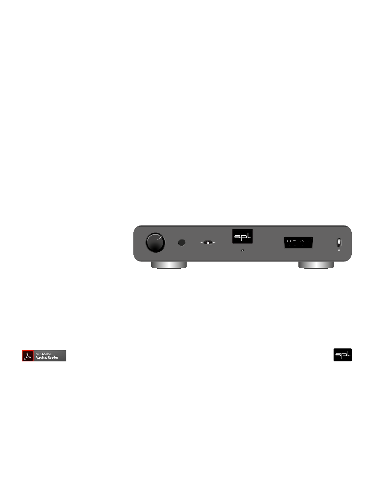
and thank you for choosing the Director.
The Director combines two units in one: a reference-class preamplifier with six inputs ( x analog and x digital)
and both balanced and unbalanced outputs as well as a reference-class DA converter for PCM up to kHz and
up to Double Rate DSD (DSD).
VOLTAiR technology is what we also call the SPL V Rail Technology within the Professional Fidelity series. This
makes the Director an outstandig device in terms of dynamic range, signal-to-noise ratio and headroom delivering an
exceptional sound experience with invincible serenity, transparancy and realness.
VOLTAiR
120V DC Audio R ail
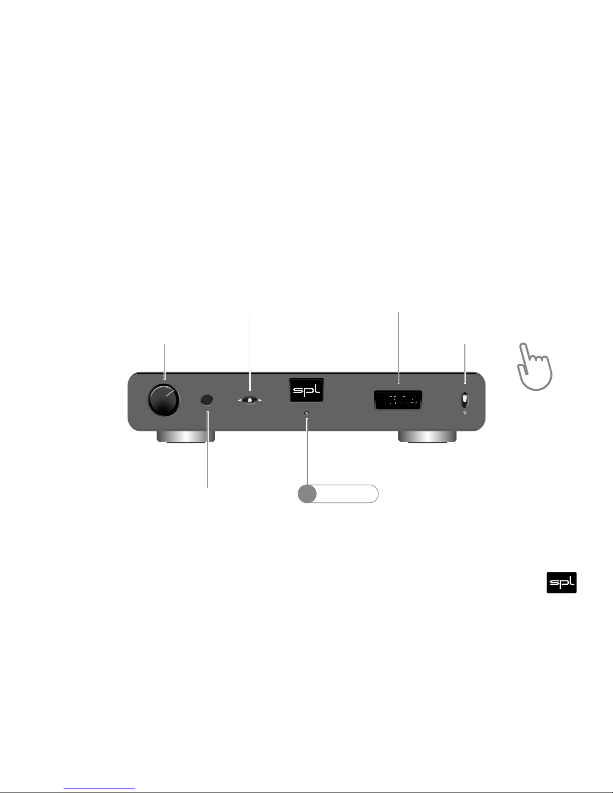
V
O
L
U
M
E
ON
DAC Preamplifier
Director
SOURCE
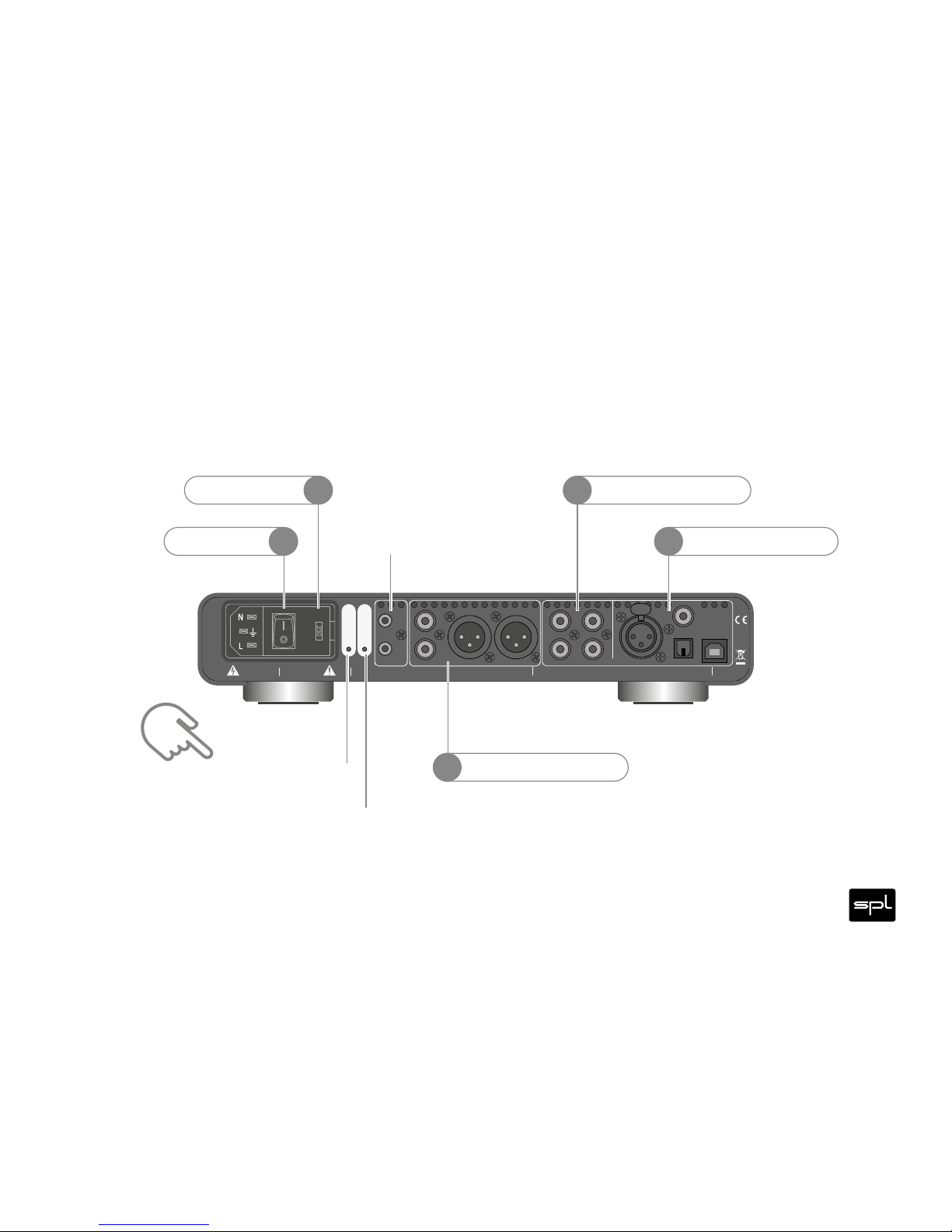
RISK OF ELEC TRIC SHO CK
DO NOT OPEN
CAUTION
RISQUEDE CHOC ÉLECTRIQUE
NE PAS OUVRIR
ATTENTION
USB
AES
OPTICAL
COAX
IR
L
R
L
R
L
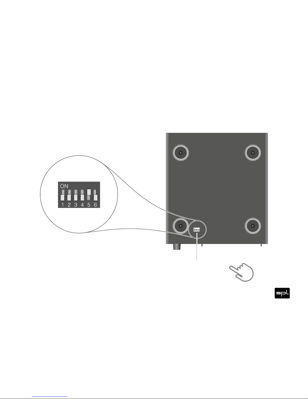
12
ANALOG < SOURCES > DIGITAL
1 ON: RCA Di rect Out
2 ON: XLR Di rect Out 5 ON: Ref +15dB
6 ON: Ref +18dB
3 ON: Zero f lag auto-m ute enabled
4 ON: RCA In -10d BV to 0dBuON BOTTOM SIDE:
DIP SWITCHES
Made in
Germany
OUT OUT R OUT L
R
B
A
Voltage Se lection: 1. Re move Fuse Hold er
2. Excha nge Fuses 3. Fl ip Over 4. Rei nstall
~115V A C/~230V A C, 50 Hz/60 Hz, P max . 45 W
Fuses: 23 0 V: T 500mA L 250V, 115 V: T 1 A L 250V
AMP CTL
IR
PGM IR
PGM
SOURCE
VOLUME
Refer to
Manual